1
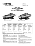
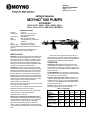
Section:
®
MOYNO 500 PUMPS
Page: 1 of 6
Date: March1, 1998
SERVICE MANUAL
MOYNO® 500 PUMPS
600 SERIES
60301, 61001, 62201, 63301, 65501, 60311,
61011, 62211, 63311, AND 65511* MODELS
DESIGN FEATURES
Cast iron
Heavy duty chrome plated
AISI 416 stainless steel
Pump Stator:
NBR (Nitrile)
Shaft:
AISI 416 stainless steel
Bearings:
Prelubricated, fully sealed ball
bearings
Seal:
Mechanical or packing
Flexible Joint:
Prelubricated and sealed
*Packing Models available through retrofit kit. See
page 6.
Note: Alternate elastomers available. Refer to
Repair/Conversion kit numbers. page 6.
Housing:
Pump Rotor:
INSTALLATION
Mounting. Provide the proper alignment between the
pump and drive by mounting both to a common flat
base. Pump may be mounted in any position. When
mounting vertically, it is necessary to keep bearings
above seals to prevent possible seal leakage into
bearings. Loosen screws on body support and stator
support to rotate pump to desired position.
Pre-Wetting. Prior to connecting pump, wet pump
elements and mechanical seal or packing by adding
fluid to be pumped into suction port. Turn shaft over
several times in a clockwise direction when viewed
from the shaft end to work fluid into pump elements.
Piping. Piping to pump should be self-supporting to
avoid excessive strain on pump housings. See Table
1 for suction and discharge port sizes of each pump
model. Use pipe ‘dope” or tape to facilitate
disassembly and to provide seal.
Drive. On belt driven units, adjust belt tension to point
of non-slip. Do not overtighten.
On direct drive units, coupling components should be
aligned and spaced at least 1/16” apart.
Pump rotation must be clockwise when facing shaft.
Check direction of rotation before startup.
Maximum speed is 1750 rpm.
Water Flush of Packing (Packing Models Only).
The packing may be either grease lubricated through
a grease fitting in the stuffing box or have plumbing
connected to the housing to allow a water flush.
When the material being pumped is abrasive in
nature, it may be advantageous to flush the packing
to prevent leakage under packing and excessive shaft
wear.
Clean water can be injected through a 1/8” NPT
tapped hole that normally houses the grease fitting for
lubricating the packing. The water can be permitted to
leak axially along the shaft in either direction.
OPERATION
Self-Priming. With wetted pumping elements, the
mechanical seal model pump is capable of 15 feet of
suction lift when operating at 1750 rpm with pipe size
equal to port size. The packing model is capable of 25
feet of suction lift.
DO NOT RUN DRY. Unit depends on liquid pumped
for lubrication. For proper lubrication, flow rate should
be at least 10% of rated capacity.
Pressure and Temperature Limits. See Table 1 for
maximum discharge pressure of each model. Unit is
suitable for service at 10° to 160°F with NBR (Nitrile),
and to 210°F with EPDM (Ethylene-Propylene-Diene
Terpolymer) elastomers.
Storage. Always drain pump for extended storage
periods using pipe plug in suction housing.
Table 1. Pump Data
Pump
Model
Suction Port
(NPT)
Discharge
Port_(NPT)
Discharge
Pressure (psig)
*Minimum
Starting Torque
(IN-LB)
60301
60311
61001
61011
62201
62211
63301
63311
65501
65511
3/4
3/4
3/4
1-1/4
1-1/4
1/2
3/4
3/4
1-1/4
1-1/4
600
600
300
150
60
95
180
90
70
60
*Based on water at ambient temperature.
Page 2
TROUBLE SHOOTING
WARNING: Before making adjustments,
disconnect power source and
thoroughly bleed pressure from
system. Failure to do so could result
in electric shock or serious bodily
harm.
Failure To Pump.
1. Belt or coupling slip: Adjust belt tension or tighten
set screw on coupling.
2. Wrong rotation: Rotation must be clockwise when
facing shaft.
3. Excessive suction lift, vacuum or obstruction in
suction piping.
4. Flexible joint broken; possible excessive
pressure:
Replace joint, check pressure at discharge port.
Will Not Start.
1. Insufficient horsepower: Check motor starting
torque for minimum model starting torque given in
Table 1.
2. Low voltage: Check power supply.
Pump Overloads.
1. Excessive discharge pressure: Check discharge
pressure for maximum rating given in Table 1
above. Check for obstruction in discharge pipe.
2. Excessive temperature: Check fluid temperature
for a maximum of 160°F.
3. Belt or coupling slip: Check pressure at discharge
port.
4. Loose bond in stator: High temperature and
caustics will cause bond between rubber and
tube to fail. Replace stator, check fluid
temperature and pressure at discharge port.
5. Fluid viscosity too high: Recommended maximum
RPM.
Viscosity CP
1-300
300-1,000
1,000-2,000
2,000-5,000
5,000-10,000
10,000-20,000
6.
Limit RPM
1750
1200
700
350
180
100
Motor connected incorrectly: Motor wired for 230
VAC, connected to 115 VAC service.
Noisy Operation.
1. Starved suction: Check fluid supply, length of
suction line, and obstructions in pipe.
2. Bearings worn: Replace parts; check alignment,
belt tension, pressure at discharge port.
3. Broken flexible joint: Replace part; check
pressure at discharge port.
4.
Insufficient mounting: Mount to be secure to firm
base. Vibration induced noise can be reduced by
using mount pads and hose on suction and
discharge ports.
Poor Performance.
1. Low pressure; worn stator: Replace stator: check
for excessive abrasive material in fluid, check for
run dry condition.
Mechanical Seal Leakage (Mechanical Seal
Models Only).
1. Leakage at startup: If leakage is slight, allow
pump to run several hours to let faces run in.
2. Persistent seal leakage: Faces may be cracked
from freezing or thermal shock. Replace seal.
Packing Leakage (Packing Models Only).
1. Leakage at startup: Adjust packing as outlined in
maintenance instructions.
Note: Slight leakage is necessary for lubrication of
packing.
2. Persistent leakage: Packing rings and/or shaft
may be worn. Replace parts as required.
Pump Will Not Prime.
1. Air leak on suction side: Check pipe connections.
Suction lift over 15 ft. will cause seal faces to
open.
2. Defective mechanical seal: Inspect and repair as
necessary.
MAINTENANCE
General. These pumps have been designed for a
minimum of maintenance, the extent of which is
routine lubrication and adjustment of packing. The
pump is one of the easiest to work on in that the main
elements are very accessible and require few tools to
disassemble.
Packing Lubrication (Packing Models Only). The
zerk fitting on the top of the packing housing leads to
the lantern ring halves in the mid-section of the
packings. At least once a week, inject a small quantity
of good quality grease, such as MPG-2 Multi Purpose
Grease (DuBois Chemical), or equivalent, into the
zerk fitting to lubricate the packings.
Packing Adjustment (Packing Models Only).
Packing gland attaching nuts should be evenly
adjusted so they are little more than finger tight. Overtightening of the packing gland may result in
premature packing failure and possible damage to the
shaft and gland.
When the packing is new, frequent minor
adjustments are recommended for the first few hours
of operation in order to compress and seat the
packing. Be sure to allow slight leakage for lubrication
of packing.
When excessive leakage can no longer be
regulated by tightening the gland nuts, remove and
replace the packings in accordance with the
DISASSEMBLY and REASSEMBLY instructions. The
entire pump need not be disassembled to replace the
packings.
Bearing Lubrication. The prelubricated, fully sealed
bearings do not require additional lubrication.
Page 3
PUMP DISASSEMBLY
PUMP ASSEMBLY
WARNING: Before
disassembling
pump,
disconnect
power
source
and
thoroughly bleed pressure from
system. Failure to do so could result
in electric shock or serious bodily
harm.
1. Disconnect power source.
2. Remove suction and discharge piping.
3. Reducer (9) may be removed from stator (21) by
unscrewing in a counter-clockwise direction (RH
thread).
4. Remove stator support screws (112B) and
remove top half of stator support(s) (38).
5. Stator (21) may be removed from suction housing
(2) by unscrewing in a counter-clockwise direction
(RH thread). Use a strap wrench on stator to
avoid crushing with a pipe wrench. Pull stator (21)
from rotor (22). To assist removal of stator, hold
shaft (26) from turning and turn stator clockwise
when facing suction housing after disengaging
thread.
6. Remove screws (112) holding suction housing (2)
to bearing housing (1). Remove suction housing
and suction housing gasket (83).
7. The rotor (22) and flexible joint (24) may be
removed using the following procedure (do not
bend joint more than 15 degrees).
a. Remove rotor (22) from flexible joint (24) by
using a punch to remove rotor pin (46).
Support joint while removing pin.
Note: On Model 603 only, remove adaptor (264)
from rotor by turning in a counter-clockwise
direction (RH Thread.)
b. Remove joint (24) from shaft (26) by using a
punch to remove shaft pin (46).
8. Mechanical Seal Models. Carefully slide
mechanical seal (69) off shaft (26). Carefully pry
seal out of bearing housing (1). If any parts of
mechanical seal are worn out or broken, the
complete assembly should be replaced. Seal
components are matched parts and are not
interchangeable.
9. Packing Models. Remove bolts attaching
packing gland housing (3) to bearing housing (1)
and remove packing gland housing. Disconnect
drive shaft extension (27) by using a punch to
remove shaft pin
(46).
The packing (42) can be removed without removing
the shaft (27) using the following procedure:
a. Remove gland bolts (47).
b. Slide gland (41) away from packing (42).
c. Pull out packing (42) and lantern ring halves
(57) using a packing-removing tool.
Note: If shaft (27) has been removed, the packing
can be removed easily by pushing out from
pump side of packing gland housing (3).
10. The bearings (29 and 30) and shaft (26)
assembly can be removed from bearing housing
(1) after snap ring (66) has been removed. To
remove the shaft assembly, lightly tap the shaft at
the flexible joint connection end using a block of
wood to protect the shaft. The bearings may be
pressed off the shaft.
1. Press radial bearing (29) and thrust bearing (30)
on shaft (26), and locate slinger ring (77) on the
shaft near the radial bearing.
Note: When replacing bearings, always press on the
inner race when assembling to shaft, and on
the outer race when pressing bearings into the
housings.
Press
shaft assembly into bearing housing (1)
2.
securing with snap ring (66).
3. Mechanical Seal Models. Install mechanical seal
(69) using the following procedure:
a. Clean and oil sealing faces using a clean light
oil (not grease).
Caution: Do not use oil on EPDM parts.
Substitute glycerin or soap and water.
b. Oil the outer surface of the seal seat, and push
the assembly into the seal bore in the bearing
housing (1), seating it firmly and squarely.
c. After cleaning and oiling shaft, slide the seal
body along the shaft until it meets the seal
seat.
d. Install seal spring and spring retainer on shaft.
4. Packing Models. Install packing before installing
shaft assembly using the following procedure:
a. Lubricate each individual ring of packing (42)
with a grease that is insoluble in the fluid being
pumped.
b. Individually assemble each ring of packing
loosely in the stuffing box of the packing gland
housing (3). Seven rings of 1/4” square plus 2
lantern ring halves required—assemble with 3
rings, 2 lantern ring halves (57), followed by 4
rings. Stagger split in rings.
c. Loosely install packing gland (41) in packing
gland housing (3) using gland bolts (47).
d. Attach drive shaft extension (27) to drive shaft
(26) by installing pin (46). Support shaft during
installation.
e. Install slinger ring (77) on drive shaft extension
(27).
f. Slide packing gland housing (3) on drive shaft
extension, and attach to bearing housing with
bolts (112).
5. The flexible joint (24) and rotor (22) may be
installed using the following procedure (do not
bend joint more than 15 degrees):
Note: On model 603 only, pin adaptor (264) to
flexible joint (24) with rotor pin (46), then
thread rotor (22) on adaptor by turning
clockwise (RH Thread.)
a. Pin flexible joint (24) to shaft (26) using shaft
pin (46).
b. Pin rotor (22) to joint using rotor pin (46).
Support joint while installing pin.
6. Secure suction housing gasket (83) and suction
housing (2) to bearing housing (1) using lock
washers (215) and screws (112).
7. Screw reducer (9) on stator (21) in a clockwise
direction (RH thread).
Note: Apply pipe “dope” on all pipe threads before
assembly.
Page 4
8. Lubricate
rotor (22) surface to assist
installation of stator (21). Slide stator on rotor,
using stator support(s) (38) as a guide, and
screw into suction housing (2) by turning
clockwise (RH threads). An additional assist in
installing stator is to lock the shaft from turning
and rotate the stator counterclockwise while
pushing towards suction housing. Care should
be taken to insure that flexible joint does not
bend more than 15 degrees.
9. Secure top and bottom halves of stator
support (38) together using screws (112B).
Model 603 requires stator support bushings
(71) between stator and stator support.
10. Proceed as in installation instructions.
WARNING: Replace belt or coupling guards
before reconnecting power.
Page 5
PARTS LIST
Item
No.
Description
1
2
‡3
9
*21
*22
24
26
‡27
29
30
37
38
‡41
‡42
46
‡47
‡57
66
@69
71
77
*83
@112
‡112
112A
112B
Bearing Housing
Suction Housing
Packing Housing
Reducer
Stator
Rotor
Flexible Joint
Drive Shaft
Drive Shaft Extension
Radial Bearing
Thrust Bearing
Body Support
Stator Support
Packing Gland
Packing
Rotor Pin/Shaft Pin (3 req.)
Gland Bolt (2 req.)
Lantern Ring Half (2 req.)
Snap Ring
Mechanical Seal
Stator Support Bushing (2 req.)
Slinger Ring
Suction Housing Gasket
Screw (4 req.)
Screw (8 req.)
Screw (2 req.)
Screw (2 req.)
‡115
162
202
@215
‡215
261
264
265
Zerk Fitting
Support Shim
Shaft Key
Lock Washer (4 req.)
Lock Washer (8 req.)
Pipe Plug
Rotor Adaptor
Stator Adaptor
Pump Model Number
60301
61001
60311
61011
62201
62211
63301
63311
65501
65511
330-3552-000
330-2112-001
320-6110-000
320-6108-006
330-4606-000
330-2112-003
‡340-2368-000
320-1414-004
320-5466-006 320-3902-004
330-4607-000 330-4608-000
320-3944-000
330-3553-000
‡330-4586-000
630-0503-051
630-0503-051
330-3554-000
330-4461-000
‡320-0003-004
‡340-3396-008
320-4486-003
‡619-1530-241
‡320-6585-000
320-2794-000
@320-3945-000
320-6539-000
330-2608-002
330-4609-000
330-0413-000
320-5306-000
320-6384-000
320-3028-000
@619-1520-161
‡619-1520-161
619-1530-281
@619-1520-163
‡619-1520-363
619-1530-241
‡320-2503-001
‡320-0077-003
611-0030-200
@623-0010-401
‡623-0010-401
610-0120-021
320-6388-000
320-6389-001
‡ Use only on Packing Gland Models (Model No. ends with 11)
@ Use only on Mechanical Seal Models (Model No. ends with 01).
* Recommended spare parts.
320-6539-000
330-2612-001
330-4610-000
Page 6
REPAIR/CONVERSION KIT NUMBERS (EPDM ELASTOMER)
Item
No.
–
21
69
24
Description
Kit No.
•
Stator
•
Seal
•
Joint
Pump Models
603
610
622
633
655
311-9129-000
320-6470-006
311-9130-000
320-6471-006
311-9131-000
320-6472-004
320-6380-000
320-6523-000
311-9132-000
320-6473-002
311-9133-000
320-6474-001
REPAIR/CONVERSION KIT NUMBERS
(ABRASION RESISTANT SEAL)
Description
All Mechanical Seal Models Only
NBR Kit No.
EPDM Kit No.
320-6505-000
320-6506-000
NBR = Nitrile
EPDM = Ethylene Propylene Diene Terpolymer
REPAIR/CONVERSION KIT NUMBERS
(PACKING GLAND)
Item
No.
–
3
27
41
42
46
47
57
112
115
215
All Packing Gland Models
Description
Kit No.
•
Packing Housing
•
Drive Shaft Extension
•
Packing Gland
•
Packing Set
•
Shaft Pin (3 req.)
•
Gland Bolt (2 req.)
•
Lantern Ring Half (2 req.)
•
Screw (4 req.)
•
Zerk Fitting
•
Lock Washer (4 req.)
© 1999 by Moyno, Inc.
® Moyno is a registered trademark of Moyno, Inc.
311-9049-000
340-2368-000
330-4586-000
320-0003-104
340-3351-008
320-4486-003
619-1530-241
320-6385-000
619-1520-161
220-2503-001
623-0010-401
Printed in U.S.A.