1
NX-300
CIRCUIT DESCRIPTION
1. Overview
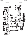
2. Frequency Configuration
The NX-300 is a UHF portable transceiver designed to
operate in the frequency range of 450 to 520MHz. The unit
consists of receiver, transmitter, phase-locked loop (PLL)
frequency synthesizer, base band parts, power supply, and
control circuits.
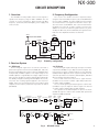
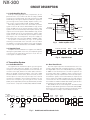
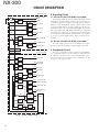
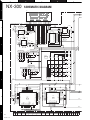
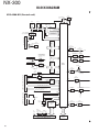
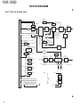
The receiver is a double-conversion superheterodyne
using the first intermediate frequency (IF) of 58.05MHz and
the second IF of 450kHz. Incoming signals from the antenna
are mixed with the local signal from the PLL circuit to produce the first IF of 58.05MHz. This is then mixed with the
57.6MHz second local oscillator output to produce the
450kHz second IF. The transmit signal frequency is generated by the PLL VCO, and modulated by the signal from the
DSP. It is then amplified and fed to the antenna.
CF
450kHz
ANT
TX/RX:450~520MHz
RF
AMP
SP
MCF
58.05MHz
19.2MHz
VC
TCXO
MIX
IF AMP
x3
57.6MHz
391.95~
461.95MHz
PA
AMP
TX
AMP
PLL
VCO
450~520MHz
Fig. 1
Base band circuit
1st MIX
ANT
SW
AF
AMP
MIC
MIC
AMP
Frequency configuration
3. Receiver System
3-1. RF Circuit
3-2. IF Circuit
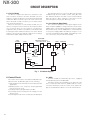
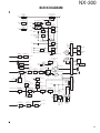
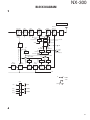
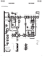
An incoming RF signal from the antenna terminal is
passed through the antenna switch (D606, 607, 709 ,711)
and then the bandpass filter (L721, L722). The bandpass filter
is adjusted by a variable capacitor. The input voltage to the
variable capacitor is regulated by the voltage output from the
D/A converter (IC703). The signal is amplified by an RF amplifier (Q705), and passed through the bandpass filter (L713,
714, 715). The resulting signal is applied to the first mixer
(Q703), where it is mixed with the first local oscillator signal
output from the frequency synthesizer to produce the first IF
(58.05MHz).
The first IF signal is passed through a four-pole monolithic
crystal filter (XF700) to reject adjacent channel signals. The
filtered first IF signal is amplified by the first IF amplifier
(Q701) and then applied to the lF system IC (IC701). The IF
system IC provides a second mixer, AGC amplifier, and RSSI
(Received Signal Strength Indicator).
The second mixer mixes the first IF signal with the
57.6MHz of second local oscillator output and produces the
second IF signal of 450kHz.
The second IF signal is passed through the ceramic filter
(CF700) to reject the adjacent channel signal. The filtered
second IF signal is amplified by the AGC amplifier.
The signal from the AGC amplifier is input to the ASIC
(IC108) through the ceramic filter (CF701) and operational
amplifier (IC700 and IC410).
ANT
D606,D607
RF AMP
1st MIX
Q705 L713~L715 Q703
L612~L614 D709,D711 L721,L722
ANT
LPF
BPF
BPF
SW
MCF
XF700
IF AMP
Q701
CF701
IC701
MIX, AGC
BPF
IC700
BPF
2nd OSC
1st PLL OSC (PLL)
X500
VC
TCXO
Q700
x3
BPF
CF700
19.2MHz
IC410
IC704
IC108
ASIC
IC707
SW
IC713
(2/2)
IC703
VOL
IC408
IC409
IC413
INT. SP
SW
IC412
AMT
EXT. SP
INAMT
EXAMT
IC102
DSP
Fig. 2
RF and IF circuit
9