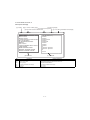
1
TopPage
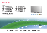
LC-40/46LE830E, RU/831E, S
SERVICE MANUAL
No. S41P640LE830E
LCD COLOUR TELEVISION
LC-40LE830E/RU
LC-46LE830E/RU
LC-40LE831E/S
MODELS LC-46LE831E/S
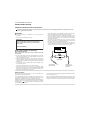
In the interests of user-safety (Required by safety regulations in some countries) the set should be restored to its original condition and only parts identical to those specified should be used.
CONTENTS
SAFETY PRECAUTION
IMPORTANT SERVICE SAFETY
PRECAUTION.....................................................i
Precautions for using lead-free solder ...............ii
End of life disposal ............................................ iii
OUTLINE
MAJOR SERVICE PARTS ................................iv
CHAPTER 1. SPECIFICATIONS
[1] SPECIFICATIONS ......................................... 1-1
CHAPTER 2. OPERATION MANUAL
[1] Parts Name .................................................... 2-1
[2] OPERATION MANUAL .................................. 2-5
CHAPTER 3. DIMENSIONS
[1] DIMENSIONS
(LC-40LE830E, RU/831E, S) ......................... 3-1
[2] DIMENSIONS
(LC-46LE830E, RU/831E, S) ......................... 3-2
CHAPTER 4. REMOVING OF MAJOR PARTS
[1] REMOVING OF MAJOR PARTS
(LC-40LE830E, RU/831E, S) ......................... 4-1
[2] REMOVING OF MAJOR PARTS
(LC-46LE830E, RU/831E, S) ......................... 4-6
[3] The location putting on the heat measure
sheet ............................................................ 4-11
[4] Precautions for assembly............................. 4-13
[5] The way of detaching Rear Cabinet............. 4-15
CHAPTER 5. ADJUSTMENT
[1] ADJUSTMENT PROCEDURE ......................5-1
CHAPTER 6. TROUBLESHOOTING TABLE
[1] TROUBLESHOOTING TABLE ......................6-1
[2] LED flashing specification at the time of the
error .............................................................6-18
CHAPTER 7. MAJOR IC INFORMATIONS
[1] MAJOR IC INFORMATIONS .........................7-1
CHAPTER 8. OVERALL WIRING/SYSTEM BLOCK
DIAGRAM
[1] OVERALL WIRING DIAGRAM
(LC-40LE830E, RU) ......................................8-1
[2] OVERALL WIRING DIAGRAM
(LC-40LE831E, S) .........................................8-2
[3] OVERALL WIRING DIAGRAM
(LC-46LE830E, RU) ......................................8-3
[4] OVERALL WIRING DIAGRAM
(LC-46LE831E, S) .........................................8-4
[5] SYSTEM BLOCK DIAGRAM
(LC-40/46LE830E, RU) .................................8-5
[6] SYSTEM BLOCK DIAGRAM
(LC-40/46LE831E, S) ....................................8-6
Parts Guide
Parts marked with "
" are important for maintaining the safety of the set. Be sure to replace these parts with specified ones for maintaining the
safety and performance of the set.
This document has been published to be used for
after sales service only.
The contents are subject to change without notice.
LC-40/46LE830E, RU/831E, S
LC-40LE830E
SAFETY PRECAUTION
Service Manual
IMPORTANT SERVICE SAFETY PRECAUTION
Service work should be performed only by qualified service technicians who are thoroughly familiar with all safety checks and the
servicing guidelines which follow:
WARNING
•
1. For continued safety, no modification of any circuit should be
attempted.
Use an AC voltmeter having with 5000 ohm per volt, or higher, sensitivity or measure the AC voltage drop across the resistor.
•
Connect the resistor connection to all exposed metal parts having a
return to the chassis (antenna, metal cabinet, screw heads, knobs
and control shafts, escutcheon, etc.) and measure the AC voltage
drop across the resistor.
All checks must be repeated with the AC cord plug connection
reversed. (If necessary, a nonpolarized adaptor plug must be used
only for the purpose of completing these checks.)
Any reading of 1.05 V peak (this corresponds to 0.7 mA peak AC.)
or more is excessive and indicates a potential shock hazard which
must be corrected before returning the monitor to the owner.
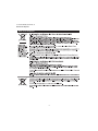
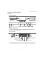
2. Disconnect AC power before servicing.
CAUTION:
FOR CONTINUED PROTECTION AGAINST A
RISK OF FIRE REPLACE ONLY WITH SAME
TYPE FUSE.
F7001 (5A/250V)
DVM
AC SCALE
BEFORE RETURNING THE RECEIVER
(Fire & Shock Hazard)
1.5k ohm
10W
Before returning the receiver to the user, perform the following
safety checks:
3. Inspect all lead dress to make certain that leads are not pinched,
and check that hardware is not lodged between the chassis and
other metal parts in the receiver.
0.15 µF
TEST PROBE
4. Inspect all protective devices such as non-metallic control knobs,
insulation materials, cabinet backs, adjustment and compartment
covers or shields, isolation resistor-capacitor networks, mechanical
insulators, etc.
5. To be sure that no shock hazard exists, check for leakage current
in the following manner.
•
Plug the AC cord directly into a 220~240 volt AC outlet.
•
Using two clip leads, connect a 1.5k ohm, 10 watt resistor paralleled by a 0.15µF capacitor in series with all exposed metal cabinet
parts and a known earth ground, such as electrical conduit or electrical ground connected to an earth ground.
TO EXPOSED
METAL PARTS
CONNECT TO
KNOWN EARTH
GROUND
///////////////////////////////////////////////////////////////////////////////////////////////////////////////////////////////////////////////////////////////////////////////////////////////////////////////////////////////////////////
SAFETY NOTICE
Many electrical and mechanical parts in LCD color television have
special safety-related characteristics.
For continued protection, replacement parts must be identical to those
used in the original circuit.
These characteristics are often not evident from visual inspection, nor
can protection afforded by them be necessarily increased by using
replacement components rated for higher voltage, wattage, etc.
The use of a substitute replacement parts which do not have the same
safety characteristics as the factory recommended replacement parts
shown in this service manual, may create shock, fire or other hazards.
Replacement parts which have these special safety characteristics are
identified in this manual; electrical components having such features
are identified by “
” and shaded areas in the Replacement Parts
List and Schematic Diagrams.
///////////////////////////////////////////////////////////////////////////////////////////////////////////////////////////////////////////////////////////////////////////////////////////////////////////////////////////////////////////
i
LC-40/46LE830E, RU/831E, S
Precautions for using lead-free solder
Employing lead-free solder
•
“PWBs” of this model employs lead-free solder. The LF symbol indicates lead-free solder, and is attached on the PWBs and service manuals. The
alphabetical character following LF shows the type of lead-free solder.
Example:
L F a/a
LFa
Indicates lead-free solder of tin, silver and copper.
Indicates lead-free solder of tin, silver and copper.
Using lead-free wire solder
•
When fixing the PWB soldered with the lead-free solder, apply lead-free wire solder. Repairing with conventional lead wire solder may cause damage or accident due to cracks.
As the melting point of lead-free solder (Sn-Ag-Cu) is higher than the lead wire solder by 40 °C, we recommend you to use a dedicated soldering
bit, if you are not familiar with how to obtain lead-free wire solder or soldering bit, contact our service station or service branch in your area.
Soldering
•
As the melting point of lead-free solder (Sn-Ag-Cu) is about 220 °C which is higher than the conventional lead solder by 40 °C, and as it has poor
solder wettability, you may be apt to keep the soldering bit in contact with the PWB for extended period of time. However, Since the land may be
peeled off or the maximum heat-resistance temperature of parts may be exceeded, remove the bit from the PWB as soon as you confirm the
steady soldering condition.
Lead-free solder contains more tin, and the end of the soldering bit may be easily corroded. Make sure to turn on and off the power of the bit as
required.
If a different type of solder stays on the tip of the soldering bit, it is alloyed with lead-free solder. Clean the bit after every use of it.
When the tip of the soldering bit is blackened during use, file it with steel wool or fine sandpaper.
•
Be careful when replacing parts with polarity indication on the PWB silk.
Lead-free wire solder for servicing
Part No.
ZHNDAi123250E
ZHNDAi126500E
ZHNDAi12801KE
Description
J
J
J
φ0.3mm 250g (1roll)
φ0.6mm 500g (1roll)
φ1.0mm 1kg (1roll)
Code
BL
BK
BM
ii
LC-40/46LE830E, RU/831E, S
End of life disposal
End of life disposal
iii
LC-40/46LE830E, RU/831E, S
LC-40LE830E
OUTLINE
Service Manual
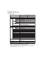
MAJOR SERVICE PARTS
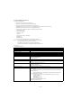
PWB Unit
Ref No.
N
N
N
N
N
N
N
N
N
N
Parts No.
DKEYDF733FM51
DKEYDF733FM52
DUNTKF494FM02
DUNTKF770FM51
RUNTKA869WJQZ
RUNTKA819WJQZ
RUNTKA787WJQZ
RUNTKA791WJQZ
RUNTK4909TPZT
RUNTK4909TPZM
Description
MAIN Unit (LC-40/46LE830E, RU) (*1)
MAIN Unit (LC-40/46LE831E, S) (*1)
R/C, OPC Unit
ICON Unit
TOUCH SENSOR KEY Unit (*2)
IR TRANSMITTER Unit
POWER Unit (LC-40LE830E, RU/831E, S)
POWER Unit (LC-46LE830E, RU/831E, S)
LCD CONTROL Unit (LC-40LE830E, RU/831E, S)
LCD CONTROL Unit (LC-46LE830E, RU/831E, S)
NOTE: (*1) Replace MAIN PWB Unit (DKEYDF733FM**) in case of IC8401 or IC3303 failure.
(*2) TOUCH SENSOR KEY Unit (RUNTKA869WJQZ) reuse will be impossible, once it is stuck on front cabinet and exfoliates.
OTHER Unit
Ref No.
N
N
Parts No.
R1LK400D3GW50Y
R1LK460D3GW40Y
Description
40" LCD Panel Module Unit (LK400D3GW50Y) (LC-40LE830E, RU/831E, S)
46" LCD Panel Module Unit (LK460D3GW40Y) (LC-46LE830E, RU/831E, S)
IC For Exclusive Use Of The Service
Ref No.
IC2001
Parts No.
RH-iXD241WJN2Q
Description
IC R5F21368CNFP (Monitor Microcomputer)
Q'ty
1
Description
Main Unit to Power Unit (PD)
Main Unit to Touch Sensor/IR Transmitter Units (RC)
Main Unit to ICON Unit (CI)
Main Unit to Speaker (SP)
Main Unit to LCD Control Unit (PL)
Power Unit to LCD Control Unit (LW)
Main Unit to Woofer (SB)
Q'ty
1
1
1
1
1
1
1
Service Jigs
Ref No.
N
N
N
N
N
N
N
Parts No.
QCNW-L795WJQZ
QCNW-L798WJQZ
QCNW-L796WJQZ
QCNW-K595WJQZ
QCNW-G405WJQZ
QCNW-F676WJQZ
QCNW-K597WJQZ
iv
LC-40/46LE830E, RU/831E, S
CHAPTER 1. SPECIFICATIONS
LC-40LE830E
Service Manual
[1] SPECIFICATIONS
LCD COLOUR TV (40"/102 cm),
LC-40LE830E, LC-40LE830RU
LC-40LE831E, LC-40LE831S
Item
LCD COLOUR TV (46"/117 cm),
LC-46LE830E, LC-46LE830RU
LC-46LE831E, LC-46LE831S
LCD panel
117 cm (46") X-Gen panel
102 cm (40") X-Gen panel
1,920 x 1,080 x 4 dots
PAL/SECAM/NTSC 3.58/NTSC 4.43/PAL 60
CCIR (B/G, I, D/K, L/L’)
DVB-T (2K/8K OFDM), DVB-C, DVB-S/S2
Resolution
Video colour system
TV
TVfunction
standard
Receiving
channel
Analogue
Digital
(830 series)
Digital
(831 series)
VHF/UHF
DVB-T (2K/8K OFDM),
DVB-T2 (1K/2K/4K/8K/16K/32K OFDM), DVB-C
IR A ch-E69 ch (Digital), E2-E69 ch, F2-F10 ch,
I21-I69 ch, IR A-IR J ch
Hyper-band, S1-S41 ch
950-2150 MHz*1
CATV
Satellite
(830 series only)
TV-tuning system
Auto Preset 999 ch (non-Nordic [DTV]),
Auto Preset 9999 ch (Nordic [DTV]),
Auto Preset 99 ch (ATV), Auto Label, Auto Sort,
Auto Preset 9999 ch (SAT [830 series only])
Stereo/Bilingual
A2/NICAM
Audio amplifier
10 W x 2 / 15 W x 1
Speaker
(103 mm x 14 mm) x 2/Ø 100 mm
Terminals Antenna
VHF/UHF
75 Din type (analogue & digital)
Satellite
75 F type (DVB-S/S2)
(830 series only)
RS-232C
EXT 1
EXT 2
EXT 3
PC
HDMI 1 (EXT 4)
HDMI 2 (EXT 5)
HDMI 3 (EXT 6)
HDMI 4 (EXT 7)
USB 1
USB 2 (HDD)
USB 3 (WIRELESS LAN)
ETHERNET (10/100)
HDMI 2/PC AUDIO (L/R)
DIGITAL AUDIO OUTPUT
C. I. (Common Interface)
OUTPUT/Headphones
SD CARD (VIDEO STORE)
OSD language
Power requirement
Power consumption (method IEC62087)
Weight
Operating temperature
D-sub 9 pin male connector
SCART (AV input, Y/C input, RGB input, TV output)
RCA pin (AV input/AUDIO L/R)
Component (AV input/Audio L/R)
mini D-sub 15 pin
HDMI (ARC)
HDMI
HDMI
HDMI
USB
USB
USB
Network connector
Ø 3.5 mm jack*2
Optical S/PDIF digital audio output
EN50221, R206001, CI Plus specification
RCA pin (AUDIO L/R)/Ø 3.5 mm jack (audio output)
SD card
Czech, Danish, Dutch, English, Estonian, Finnish, French, German,
Greek, Hungarian, Italian, Latvian, Lithuanian, Norwegian, Polish,
Portuguese, Russian, Slovak, Slovene, Spanish, Swedish, Turkish,
Ukrainian
AC 220-240 V, 50 Hz
133 W (0.2 W standby*3)
110 W (0.2 W standby*3)
19.0 kg (without stand)
13.5 kg (without stand)
23.0 kg (with stand)
16.5 kg (with stand)
0 °C to + 40 °C
The satellite channel’s frequency may vary according to satellites and antennas.
The HDMI 2 and PC terminals can both use the same audio input terminal.
Standby power consumption applies when the TV is set to not receive EPG data.
• As a part of our policy of continuous improvement, SHARP reserves the right to make design and specification
changes for product improvement without prior notice. The performance specification figures indicated are nominal
values of production units.
There may be some deviations from these values in individual units.
*1
*2
*3
1–1
LC-40/46LE830E, RU/831E, S
CHAPTER 2. OPERATION MANUAL
LC-40LE830E
Service Manual
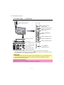
[1] Parts Name
TV (front view)
Illumination LED*1
3D infrared emitter*2
OPC sensor
Remote control sensor
*1
*2
3D mode: Blue illumination
2D mode: White illumination
This panel emits infrared signal towards the 3D glasses you wear when viewing 3D
images. Do not place anything between the 3D infrared emitter on the TV and the
infrared receiver on the 3D glasses.
TV (rear view)
USB 3 ( WIRELESS LAN) port
HDMI 2/PC AUDIO (L/R)
jack*3
USB 2 (HDD) port
ETHERNET (10/100) terminal
Satellite antenna terminal
(830 series only)
*3
DIGITAL AUDIO OUTPUT
terminal
Antenna terminal
The HDMI 2 and PC terminals can both use the same audio input terminal (HDMI 2/PC
AUDIO (L/R)). However, the proper item must be selected in the “Audio select” menu.
2–1
LC-40/46LE830E, RU/831E, S
TV (rear view) — continued
MAIN POWER switch*4
SD CARD (VIDEO
STORE) slot
OUTPUT (Headphones/
AUDIO (L/R)) terminal
USB 1 port
HDMI 1 (HDMI/ARC)
terminal
HDMI 2 (HDMI) terminal
RS-232C terminal
HDMI 3 (HDMI) terminal
HDMI 4 (HDMI) terminal
PC terminal
EXT 1 (RGB) terminal
EXT 2 (VIDEO/AUDIO
(L/R)) terminal
C.I. (COMMON
INTERFACE) slot
EXT 3 (Component/
AUDIO (L/R)) terminal
*4
When the MAIN POWER switch is turned off ( ), the amount of electric power
consumed will be reduced to 0.01 W or less. However, unlike when unplugging the AC
cord, the power is not completely disconnected.
WARNING
• Excessive sound pressure from earphones and headphones can cause hearing loss.
• Do not set the volume at a high level. Hearing experts advise against extended
listening at high volume levels.
Important information:
Satellite services are only available for the 830 model series.
2–2
LC-40/46LE830E, RU/831E, S
Remote control unit
15
16
1
2
7
17
8
18
3
4
9
10
11
19
20
12
21
1
2
3
4
5
6
5
6
13
14
22
23
24
7
8
2–3
TV (Standby/On)
ATV
Access conventional analogue TV mode.
DTV
Access digital TV mode.
SAT
Access satellite mode.
RADIO
DTV/SAT: Switch between radio and
data mode.
• When only data broadcasting (no radio
broadcasting) is transmitted by DVB,
the radio broadcasting will be skipped.
AQUOS LINK buttons
CONTROL
Display a panel to operate some
functions on the screen.
NET: “NET MENU” screen on/off.
TIME SHIFT (READY/ / / )
Temporarily record a programme you are
watching.
Numeric buttons 0-9
Set the channel. Enter desired numbers.
Set the page in teletext mode.
• When the five Nordic countries
(Sweden, Norway, Finland, Denmark
or Iceland) are selected in the country
setting from initial auto installation,
DTV services are four digits.
When another country is selected,
DTV services are three digits.
(Flashback)
Return to the previously selected
channel or external input.
(Sound mode)
Select a sound multiplex mode.
(Wide mode)
Select a wide mode.
LC-40/46LE830E, RU/831E, S
9
10
11
12
13
14
15
16
17
18
19
(Mute)
TV sound on/off.
+/- (Volume)
Increase/decrease TV volume.
MEMU
“Menu” screen on/off.
3D
Select between 3D and 2D image
viewing.
/ / / (Cursor)
Select a desired item.
OK
Execute a command.
ATV/DTV/SAT: Display “CH list” when no
other “Menu” screen is running.
END
ATV/DTV/SAT: Exit the “Menu” screen.
NET: Return to the start page.
NET
Access Net TV.
(Display information)
Display the station information (channel
number, signal, etc.) on the screen.
P. INFO
Display programme information
transmitted through digital video
broadcasting (DTV/SAT only).
(INPUT)
Select an input source.
AV MODE
Select audio/video settings.
ECO (Standard/Advanced/Off)
Select “Energy save” setting.
(Teletext)
ATV: Display analogue teletext.
DTV/SAT: Select MHEG-5 or teletext for
DTV/SAT.
20 P /
ATV/DTV/SAT: Select the TV channel.
NET: Scrolls pages up/down.
21 EPG
DTV/SAT: Display the EPG screen.
22
(Return)
ATV/DTV/SAT: Return to the previous
“Menu” screen.
NET: Return to the previous page (This
may not function for some services).
23 Buttons for useful operations
(Subtitle)
Switch subtitle languages on/off.
(Reveal hidden teletext)
(Subpage)
(Freeze/Hold)
Freeze a moving image on the screen.
Teletext: Stop updating teletext pages
automatically or release the hold mode.
24 R/G/Y/B (Colour) buttons
The coloured buttons are
correspondingly used to select the
coloured items on the screen (e.g., EPG,
MHEG-5, teletext).
2–4
Important information:
Satellite services are only available for
the 830 model series.
LC-40/46LE830E, RU/831E, S
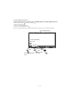
[2] OPERATION MANUAL
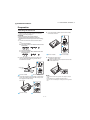
Preparation
Attaching the stand unit
4 Insert and tighten middle screws into the holes
• Before performing work, spread cushioning over the
surface on which you will be laying the TV. This will
prevent it from being damaged.
on the rear of the TV.
CAUTION
• Attach the stand in the correct direction.
• Be sure to follow the instructions. Incorrect
installation of the stand may result in the TV falling
over.
1 Confirm that there are screws with the stand
unit.
For 46 inch models
(four long screws, four middle screws and one
short screw)
For 40 inch models
(three long screws, three middle screws and
one short screw)
46 inch models
2 Attach the supporting post for the stand unit
onto the base using the long screws with a
screwdriver as shown.
40 inch models
5 Attaching the stand cover.
Insert the stand cover.
Insert and tighten a short screw into the hole
of the stand cover.
Supporting
post
46 inch models
40 inch models
3 Insert the stand into the openings on the bottom
of the TV (hold the stand so it will not drop from
the edge of the base area).
Soft cushion
46 inch models
NOTE
• To detach the stand unit, perform the steps in reverse
order.
• A screwdriver is not supplied with this product.
• The TV can be rotated up to 20 degrees to the right and
left.
40 inch models
2–5
LC-40/46LE830E, RU/831E, S
CHAPTER 3. DIMENSIONS
LC-40LE830E
Service Manual
[1] DIMENSIONS (LC-40LE830E, RU/831E, S)
Unit: mm
( 26.4 ) *2
( 26,4 ) *2
( 116.0 )
( 116,0 )
( 264.0 )
( 264,0 )
( 300.0 )
( 300,0 )
( 65.0 )
( 65,0 )
( 124.0 )
( 124,0 )
( 460.0 )
( 460,0 )
( 300.0 )
( 300,0 )
( 33.4 ) *3
( 33,4 ) *3
( 360.0 )
( 360,0 )
( 498,15 )*1
1
( 885.6 ) *1
( 885,6 ) *1
( 498.15 )*
( 636.0 )
( 636,0 )
( 588.0 )
( 588,0 )
( 938.0 )
( 938,0 )
( 174.0 )
( 174,0 )
*1
*2
*3
Active area
Thinnest part
Excluding projecting part
NOTE
• Dimensions do not include protrusions such as screws and some parts.
3–1
LC-40/46LE830E, RU/831E, S
[2] DIMENSIONS (LC-46LE830E, RU/831E, S)
Unit: mm
( 26.4 ) *2
( 26,4 ) *2
( 33.4 ) *3
( 33,4 ) *3
( 398.0 )
( 398,0 )
( 572,67 )*1
( 1018.08 ) *1
( 1018,08 ) *1
( 131.0 )
( 131,0 )
( 572.67 )*1
( 711.0 )
( 711,0 )
( 663.0 )
( 663,0 )
( 1072.0 )
( 1072,0 )
( 507.0 )
( 507,0 )
( 293.0 )
( 293,0 )
( 400.0 )
( 400,0 )
( 19.0 )
( 19,0 )
( 200.0 )
( 200,0 )
( 400.0 )
( 400,0 )
( 215.0 )
( 215,0 )
*1
*2
*3
Active area
Thinnest part
Excluding projecting part
NOTE
• Dimensions do not include protrusions such as screws and some parts.
3–2
LC-40/46LE830E, RU/831E, S
Service
CHAPTER 4. REMOVING OF MAJOR PARTS
LC-40LE830E
Manual
[1] REMOVING OF MAJOR PARTS (LC-40LE830E, RU/831E, S)
1. Removing of Stand Unit and Rear Cabinet Ass’y.
1. Remove the 1 lock screw
2. Remove the 3 lock screws
3. Remove the 1 lock screw
and detach the Stand Support Cover
and detach the Stand Unit
.
and detach the AC Cord Cover
4. Disconnect the AC wire and detach the AC Cord
5. Remove the 4 Vesa Hole Covers
, 5 lock screws
.
.
.
, 2 lock screws
and 12 lock screws
and detach the Rear Cabinet Ass’y
12 Rear Cabinet Ass'y
11
AC Cord 7
10
[AC]
[AC]
AC Cord Cover 6
5
9
8
Stand Support Cover 2
11
1
3
Stand Unit 4
4–1
.
LC-40/46LE830E, RU/831E, S
2. Removing of Speaker-L/R.
1. Remove the 8 lock screws
2. Detach the Bottom Cover
and detach the LCD CONTROL Unit Angle
.
.
3. Disconnect the SP wire.
4. Detach the Speaker-L
, Speaker-R
.
MAIN Unit
[SP]
3 Bottom Cover
2 LCD CONTROL
Unit Angle
1
[SP]
Speaker-R 5
Speaker-L
4–2
4
LC-40/46LE830E, RU/831E, S
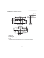
3. Removing of Connectors
1. Disconnect the following connectors from the MAIN Unit. (SB, PD, LW, PL, RC, Cl)
2. Disconnect the following connectors from the POWER Unit. (PD, L1, AS)
3. Disconnect the following connectors from the LCD CONTROL Unit. (LW, PL)
POWER Unit
[L1]
MAIN Unit
[PD]
[PL]
[AS]
[LW]
LCD CONTROL Unit
MAIN Unit
[SB]
[LW]
[PL]
[RC]
[CI]
4–3
[PD]
LC-40/46LE830E, RU/831E, S
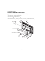
4. Removing of Speaker (Woofer), 40” LCD Panel Module Unit, MAIN Unit, POWER Unit, LCD CONTROL Unit.
1. Detach the Speaker (Woofer)
.
2. Detach the 8 LCD Fixing Angles
3. Remove the 7 Hooks
.
and detach the 40” LCD Panel Module Unit
4. Remove the 5 lock screws
and detach the Main Shield
5. Remove the 2 lock screws
and detach the MAIN Unit
6. Remove the 1 lock nut
and Terminal Angle (Bottom)
.
and Earth Spring
7. Remove the 6 lock screws
and detach the POWER Unit
8. Remove the 9 lock screws
and detach the Center Angle-L
9. Remove the 4 Connecting Cords
10.Remove the 2 lock screws
, 4 Ferrite Cores
.
.
.
and 2 Insulation Sheet
, Center Angle-R
and 6 lock screws
.
.
and detach the LCD CONTROL Unit
and detach the Connector Cord with Eco Switch
.
.
11
5
Main Shield
6
12 POWER Unit
[SB]
Speaker 1
(Woofer)
7
13 Insulation
Sheet
8 MAIN Unit
21 Earth Spring
LCD Fixing
2 Angle
LCD Fixing Angle 2
10 Terminal Angle
(Bottom)
9
2 LCD Fixing Angle
LCD Fixing Angle 2
23
2 LCD Fixing Angle
Hook 3
22
3 Hook
[AS]
Connector Cord
with Eco Switch
4 40" LCD Panel
Module Unit
LCD Fixing Angle 2
2 LCD Fixing Angle
Hook 3
3 Hook
14
3 Hook
20 LCD CONTROL Unit
14
Insulation
Sheet
13
16 Center
Angle-R
19
Ferrite
Core 18
15 Center
Angle-L
4–4
18 Ferrite Core
17 Connecting Cord
LC-40/46LE830E, RU/831E, S
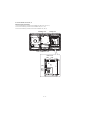
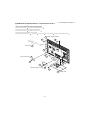
5. Removing of ICON Unit, R/C OPC Unit, IR TRANSMITTER Unit, TOUCH SENSOR KEY Unit.
1. Remove the 1 lock screw
and detach the ICON Unit
2. Detach the R/C OPC Unit
.
3. Detach the IR TRANSMITTER Unit
.
.
4. Detach the TOUCH SENSOR KEY Unit
NOTE: The TOUCH SENSOR KEY unit
.
reuse will be impossible, once it is stuck on front cabinet and exfoliates.
Front Cabinet Ass'y
TOUCH SENSOR
KEY Unit
5
[TK] [RA]
[RA]
[IR]
4
IR TRANSMITTER
Unit
ICON 2
Unit
3 R/C OPC
Unit
4–5
[CI]
1
LC-40/46LE830E, RU/831E, S
[2] REMOVING OF MAJOR PARTS (LC-46LE830E, RU/831E, S)
1. Removing of Stand Unit and Rear Cabinet Ass’y.
1. Remove the 1 lock screw
2. Remove the 4 lock screws
3. Remove the 1 lock screw
and detach the Stand Support Cover
and detach the Stand Unit
and detach the AC Cord Cover
4. Disconnect the AC wire and detach the AC Cord
5. Remove the 4 Vesa Hole Covers
, 7 lock screws
.
.
.
.
, 2 lock screws
and 12 lock screws
and detach the Rear Cabinet Ass’y
12 Rear Cabinet Ass'y
11
10
[AC]
AC Cord 7
[AC]
8
9
AC Cord Cover 6
5
11
1
Stand Support Cover 2
3
4 Stand Unit
4–6
.
LC-40/46LE830E, RU/831E, S
2. Removing of Speaker-L/R.
1. Remove the 8 lock screws
2. Detach the Bottom Cover
and detach the LCD CONTROL Unit Angle
.
.
3. Disconnect the SP wire.
4. Detach the Speaker-L
, Speaker-R
.
MAIN Unit
[SP]
3 Bottom Cover
2 LCD CONTROL
Unit Angle
1
[SP]
Speaker-R 5
Speaker-L
4–7
4
LC-40/46LE830E, RU/831E, S
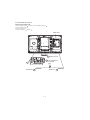
3. Removing of Connectors
1. Disconnect the following connectors from the MAIN Unit. (SB, PD, LW, PL, RC, Cl)
2. Disconnect the following connectors from the POWER Unit. (PD, L1, AS)
3. Disconnect the following connectors from the LCD CONTROL Unit. (LW, PL)
POWER Unit
[L1]
[PD]
[PL]
[AS]
[LW]
LCD CONTROL Unit
MAIN Unit
[SB]
[LW]
[PL]
[RC]
[CI]
4–8
[PD]
MAIN Unit
LC-40/46LE830E, RU/831E, S
4. Removing of Speaker (Woofer), 46” LCD Panel Module Unit, MAIN Unit, POWER Unit, LCD CONTROL Unit.
1. Detach the Speaker (Woofer)
.
2. Detach the 9 LCD Fixing Angles
3. Remove the 9 Hooks
.
and detach the 46” LCD Panel Module Unit
4. Remove the 5 lock screws
and detach the Main Shield
5. Remove the 2 lock screws
and detach the MAIN Unit
6. Remove the 1 lock nut
and Terminal Angle (Bottom)
7. Remove the 6 lock screws
.
and Earth Spring
and detach the POWER Unit
8. Remove the 13 lock screws
10.Remove the 2 lock screws
, 4 Ferrite Cores
.
and 2 Insulation Sheet
and detach the Center Angle-L
9. Remove the 4 Connecting Cords
.
.
, Center Angle-R
and 6 lock screws
.
.
and detach the LCD CONTROL Unit
and detach the Connector Cord with Eco Switch
.
.
11
5
Main Shield 6
12 POWER Unit
[SB]
Speaker 1
(Woofer)
7
13 Insulation Sheet
8 MAIN Unit
21 Earth Spring
2 LCD Fixing Angle
LCD Fixing Angle 2
9
10 Terminal Angle
(Bottom)
2 LCD Fixing Angle
LCD Fixing Angle 2
2 LCD Fixing Angle
Hook 3
22
23
3 Hook
[AS]
Connector Cord
with Eco Switch
4 46" LCD Panel
Module Unit
LCD Fixing Angle 2
2 LCD Fixing Angle
3 Hook
3 Hook
14
13
Insulation Sheet
14
16 Center
Angle-R
3 Hook
20 LCD CONTROL Unit
19
Ferrite
Core 18
15 Center
Angle-L
4–9
18 Ferrite Core
17 Connecting Cord
LC-40/46LE830E, RU/831E, S
5. Removing of ICON Unit, R/C OPC Unit, IR TRANSMITTER Unit, TOUCH SENSOR KEY Unit.
1. Remove the 1 lock screw
and detach the ICON Unit
2. Detach the R/C OPC Unit
.
3. Detach the IR TRANSMITTER Unit
.
4. Detach the TOUCH SENSOR KEY Unit
NOTE: The TOUCH SENSOR KEY unit
.
.
reuse will be impossible, once it is stuck on front cabinet and exfoliates.
Front Cabinet Ass'y
TOUCH SENSOR
KEY Unit
5
[TK] [RA]
[CI]
[RA]
2 ICON Unit
[IR]
3 R/C OPC
Unit
IR TRANSMITTER
Unit
4
4 – 10
1
LC-40/46LE830E, RU/831E, S
[3] The location putting on the heat measure sheet
1. MAIN PWB Unit
Main PWB Unit
(DUNTKF733WE**)
PSPAZC702WJKZ
The object to cool.
(The sheet is put on the back of the
board.)
The guide line is impressed on the backlight
chassis
4 – 11
LC-40/46LE830E, RU/831E, S
2. LCD Control Unit
The IC to cool
LCD control unit
(RUNTK4910TP**)
Please put [PSPAZC0062WJKZ] on the IC
4 – 12
LC-40/46LE830E, RU/831E, S
[4] Precautions for assembly
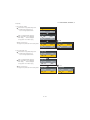
1. Attaching the touch sensor
1. After removing the release paper, attach the touch sensor keeping out dust and dirt.
2. Press the 3 circular silk positions on the PWB to fix the touch sensor. There is no problem if the pressing positions are slightly misaligned. However, do not press the connectors directly since they are very easy to break.
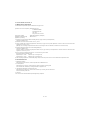
2. Points to be checked and precautions when servicing the unit
Mount the main PWB Ass’y on the backlight chassis and check that the EMI-prevention parts are not peeled and twisted from the access holes. (The
EMI-prevention parts, conductive nonwoven fabric gaskets, must be seen from the access holes.)
[Countermeasure]
Attach the conductive nonwoven fabric gaskets on the shielded case on the main PWB.
PSPAZC691WJZZ x 2 pcs
PSPAZC690WJZZ
Attach the conductive nonwoven fabric gasket on the RF terminal angle.
(PSPAZC691WJZZ)
4 – 13
LC-40/46LE830E, RU/831E, S
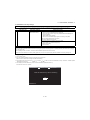
State where the main PWB and shielded case are assembled
Access hole
Access hole
The following is a drawing mounting the main PWB Ass’y on the backlight chassis. (The parts indicated by -> are the access holes for confirmation.)
(Main PWB Ass’y => State where the shielded case and RF terminal angle are mounted on the main PWB)
4 – 14
LC-40/46LE830E, RU/831E, S
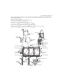
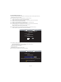
[5] The way of detaching Rear Cabinet
•
Here are the way of detaching Rear Cabinet. Please respond in following order.
1. Lay the TV set down on the desk or table with the glass side down, set the left hand between Front Cabinet and Rear Cabinet on the bottom of
right corner side.
2. Set the right hand between Front Cabinet and Rear Cabinet on the right side in the under corner.
4 – 15
LC-40/46LE830E, RU/831E, S
3. Push Rear Cabinet toward the center of TV set with right hand. At the same time, open Rear Cabinet in the back side with left hand and detach the
hook.
Figure for image
Right Hand
Left Hand
4. Detach the hooks one by one in a counterclockwise direction with changing the position of right hand.
Follow the arrows for removing
Start Position
4 – 16
LC-40/46LE830E, RU/831E, S
CHAPTER 5. ADJUSTMENT
LC-40LE830E
Service Manual
[1] ADJUSTMENT PROCEDURE
1. Adjustment method after PWB and/or IC replacement due to repair
The unit is set to the optimum at the time of shipment from the factory.
If any value should become improper or any adjustment is necessary due to the part replacement, make an adjustment according to the following procedure.
1. Procure the following units in order to replace the main unit.
MAIN UNIT: DKEYDF733FM51 (LC-40/46LE830E, RU)
MAIN UNIT: DKEYDF733FM52 (LC-40/46LE831E, S)
NOTE: [Caution when replacing IC (IC2001) in the main unit]
The above IC are Monitor microcomputer.
Before replacing the relevant part, procure the following parts in which the data have been rewritten.
IC2001
RH-iXD241WJN2Q
Monitor microcomputer
NOTE: [Caution when replacing ICs (IC8401, IC3303) in the main unit]
When replacing either IC8401 or IC3302, exchange MAIN units for DKEYDF733FM51 (LC-40/46LE830E, RU), DKEYDF733FM52 (LC-40/
46LE831E, S).
Each part should not be individually exchanged.
IC8401
IC3303
RH-iXD287WJQZQ
RH-iXD220WJQZQ
Flash
Main CPU
NOTE: HDMI ROM Writing
After replacing IC1504, execute “HDMI EDID WRITE” on the page 5/24.
Please execute it after checking MODEL NAME & INCH SIZE. are correct.
If MODEL NAME & INCH SIZE. are not correct, set them previously. (Refer to 2.)
The ROM data based on information of MODEL NAME & INCH SIZE.
1) Enter the process adjustment mode in TV.
2) Use the cursor keys (
/
) and CH keys (
/
) of R/C to select the item [HDMI EDID WRITE] on the page 5/24.
3) It is completed with OK displayed.
2. After replacing the LCD panel or LCD control/MAIN UNIT, check MODEL NAME in the following procedure.
1) Enter the process adjustment mode in TV.
2) Use the cursor keys (
/
) and CH keys (
/
) of R/C to select the item [MODEL NAME] on the page 24/24.
3) Verify that the Model name is displayed.
4) If the Model name doesn’t match, select the values of the Model name with the VOL keys (+/-).
5) After selection in Step 4), press the OK key, and it is completed with OK displayed.
6) Use the cursor keys (
/
) and CH keys (
/
) of R/C to select the item [PANEL_SIZE] on the page 24/24.
7) Verify that the panel size is displayed.
8) If the size doesn’t match, select the values of the panel size with the VOL keys (+/-).
9) After selection in Step 8), press the OK key, and it is completed with OK displayed.
10)After setting [MODEL NAME] [PANEL_SIZE], unplug the AC power cord and plug it back in.
3. After replacing the LCD panel or LCD control PWB, adjust the VCOM in the following procedure.
1) Enter the process adjustment mode.
2) Use the cursor keys (
/
) and CH keys (
/
) of R/C to select the item [VCOM ADJ] on the page 10/24.
3) Press the OK key to verify that the adjustment pattern is displayed.
4) Use VOL keys (+/-) of R/C to adjust the flicker in the center of the screen to minimum.
5) When the optimal state is achieved in Step 4), press the OK key to turn the pattern to OFF.
5–1
LC-40/46LE830E, RU/831E, S
2. Notes of Touch sensor key unit
Touch sensor key unit (RUNTKA869WJQZ) is fixed directly in Front Cabinet.
The unit cannot never be recycled when exfoliated from Front Cabinet.
Therefore, please exchange the touch sensor units when Front Cabinet is changed.
3. Method of shuts down for Power supply
Please execute the following procedures to shut down Power supply from the state of normal operation.
1) Keep touching the power supply key on the set for 5 seconds from the state of watching.
*
The screen disappears when power supply key is touched, but Keep pushing the power supply key.
2) A central icon lights between 500ms when the power supply shuts down.
Please separate the finger from the power supply key when lighting of a central icon is confirmed.
4. Entering and exiting the adjustment process mode
Please execute the following procedures to enter the adjustment process mode when the power supply shuts down.
1) While holding down the “VOL (-)” and “INPUT” keys on the set at once, touch the power supply key on the set.
Please separate the fingers from key on the set when boot-up is confirmed with lighting of a central icon etc.
After a while, The letter “K” appears on the screen. This state is in Inspection mode.
2) Next, hold down the “VOL (-)” and “CH (
)” keys on the set at once.
Multiple lines of blue characters appearing on the screen indicate that the set is now in the adjustment Process mode.
If you fail to enter the adjustment process mode (the display is the same as normal startup), retry the procedure.
3) To exit the adjustment process mode after the adjustment is done, unplug the AC power cord to force off the power.
(When the power is turned off with the remote controller, once unplug the AC power cord and plug it in again. In this case, wait for 20 seconds or
so after unplugging.)
CAUTION: Use due care in handling the information described here lest the users should know how to enter the adjustment process mode.
If the settings are tampered with in this mode, unrecoverable system damage may result.
5. Remote controller key operation and description of display in adjustment process mode
1. Key operation
Remote controller key
CH keys (
/
)
VOL keys (+/-)
Cursor ( / )
Cursor ( / )
INPUT
OK
RETURN
Main unit key
CH (
/
)
VOL (+/-)
—
—
INPUT
—
—
Remote controller key Main unit key Function
Moving an item (line) by one (UP/DOWN)
Changing a selected item setting (+1/-1)
Turning a page (PREVIOUS/NEXT)
Changing a selected line setting (+10/-10)
Input source switching (toggle switching) (TV→EXT1→ etc...)
Executing a function
Returning to a present page
Input mode is switched automatically when relevant adjustment is started so far as the necessary input signal is available.
5–2
LC-40/46LE830E, RU/831E, S
6. Description of display
(1) Present˴page / number of total pages
(4) Inducing display
(3) Present colour system
(2) Input that has been selected now
(5) Inch setting and Model name display
1/24
INPUT1
MAIN Version
BOOT Version
Monitor Version
T-CON Version/LED CON Version
NET TV KEY/MAC
CI+INFO/SECURE BOOT
MARLIN
FRC Version
TOUCH SENSOR/IR Micom Version
LAMP ERROR
MONITOR ERR CAUSE
NORMAL STANDBY CAUSE
ERROR STANDBY CAUSE
AUTO
1.00 (E 2010/**/** )
xxxxxxx
xxxxxxx
xxxxxxxx/xxxx
xxxxxxx
xxxxx/YES
xxxxxxx
xxxxxxx
xxxxxxx
0
1)xxxxxx 2)xxxxxx
3)xxxxxx 4)xxxxxx
0
0000
(6) Item name
No.
(1)
(2)
(3)
(4)
(5)
(6)
(7)
Description
Present page/number of total pages
Input that has been selected now
Present colour system
Inducing display
Inch setting and Model name display
Item name
Parameter
EURO
(7) Parameter
Display specification
2char/2char Decimal Number mark.
TUNER/DTV/INPUT1/INPUT2/INPUT3/INPUT5/INPUT6/INPUT7/etc. ⋅⋅⋅
AUTO/N358/N443/PAL/SECAM/480i/580i/1080i/50 etc. ⋅⋅⋅
EUROPE/RUSSIA/SWEDEN
Inch setting and Model name display
Max. 30 char
Max. 60 char
5–3
LC-40/46LE830E, RU/831E, S
7. List of adjustment process mode menu
The character string in brackets [ ] will appear as a page title in the adjustment process menu header.
Page
1/24
Line
Item
Description
1xxx (xxxxx)
xxxxxxx
xxxxxxx
xxxxxxxx/xxxx
xxxxxxx
xxxxx/YES
xxxxxxx
xxxxxxx
xxxxxxx
0
1)xxxxxx 2)xxxxxx
3)xxxxxx 4)xxxxxx
0
0000
Remarks (adjustment detail, etc.)
1
2
3
4
5
6
7
8
9
10
11
MAIN Version
BOOT Version
Monitor Version
T-CON Version/LED CON Version
NET TV KEY/MAC
CI+INFO/SECURE BOOT
MARLIN
FRC Version
TOUCH SENSOR/IR Micom Version
LAMP ERROR
MONITOR ERR CAUSE
Main software version
BOOT Version.
Monitor software version
T-CON/LED CON Version
NET TV KEY/MAC Address
CI+ Key Information/SECURE BOOT
12
13
NORMAL STANDBY CAUSE
ERROR STANDBY CAUSE
1
2
3
4
5
6
7
8
9
10
11
12
13
INDUSTRY INIT
INDUSTRY INIT (-Public)
PUBLIC MODE
Center Acutime
RESET
Backlight Acutime
RESET
LAMP ERROR RESET
ADJ PARAM SET
VIC XPOS
VIC YPOS
VIC SIGNAL TYPE
VIC READ
Enter
OFF
OFF
—
OFF
—
OFF
OFF
Enter
0
0
MAIN
OFF
Initialization to factory settings execution.
Initialization to factory settings execution. (Public mode is excluded)
Public mode ON/OFF setting
Main operating hours.
Main operating hours reset.
Backlight operating hours.
Backlight operating hours reset.
Lamp error reset.
ADJ PARAM SET
X-coordinate setting for VIC READ
Y-coordinate setting for VIC READ
Signal type setting for VIC READ
Picture level acquisition function
(Level appears in green on the upper right)
1
2
3
4
5
6
7
8
9
TUNER ADJ
PAL+TUNER ADJ
TUNER ADJ (SMPTE)
PAL+TUNER ADJ (SMPTE)
TUNER ADJ (SMPTE CH57)
PAL+TUNER ADJ (SMPTE CH57)
TUNER CONTRAST A_GAIN
TUNER CONTRAST D_GAIN
TUNER CONTRAST OFFSET
Enter
Enter
Enter
Enter
Enter
Enter
14
2048
256
TUNER auto adjustment execution
PAL TUNER auto adjustment execution
TUNER auto adjustment execution (SMPTE)
PAL TUNER auto adjustment execution (SMPTE)
TUNER auto adjustment execution (SMPTE CH57)
PAL TUNER auto adjustment execution (SMPTE CH57)
TUNER signal level adjustment
TUNER signal level adjustment
TUNER signal level adjustment
1
2
3
4
5
6
7
8
9
10
11
12
PAL ADJ
SECAM ADJ
N358 ADJ
PAL CONTRAST A_GAIN
PAL CONTRAST D_GAIN
PAL CONTRAST OFFSET
SECAM CONTRAST A_GAIN
SECAM CONTRAST D_GAIN
SECAM CONTRAST OFFSET
N358 CONTRAST A_GAIN
N358 CONTRAST D_GAIN
N358 CONTRAST OFFSET
Enter
Enter
Enter
14
2048
256
14
2048
256
14
2048
256
PAL adjustment
SECAM adjustment
N358 adjustment
PAL contrast adjustment
PAL contrast adjustment
PAL contrast adjustment
SECAM contrast adjustment
SECAM contrast adjustment
SECAM contrast adjustment
N358 contrast adjustment
N358 contrast adjustment
N358 contrast adjustment
1
2
3
4
5
6
HDMI CEC TEST
HDMI EDID WRITE
INSPECT USB TERM
MONIDATA READ [TEMP/OPC]
SD CARD TEST
CAUSE RESET
Enter
Enter
Enter
OFF
Enter
Enter
HDMI CEC test
HDMI EDID WRITING
Reading inspection of USB memory terminal
MONITOR Temperature/OPC Acquisition tool.
SD CARD TEST
Reset of standby cause
Number of termination due to lamp error.
Last error standby cause.
Situation that became standby at the end. (Excluding the error)
Error standby cause
2/24
3/24
4/24
5/24
5–4
LC-40/46LE830E, RU/831E, S
Page
6/24
Line
Item
Description
Remarks (adjustment detail, etc.)
1
2
3
4
5
6
7
COMP15K ALL ADJ
COMP15K MAIN Y GAIN
COMP15K MAIN CB GAIN
COMP15K MAIN CR GAIN
COMP15K Y OFFSET
COMP15K CB OFFSET
COMP15K CR OFFSET
Enter
140
150
150
64
128
128
Component 15K picture level adjustment
Y GAIN adjustment value
Cb GAIN adjustment value
Cr GAIN adjustment value
Y OFFSET adjustment value
Cb OFFSET adjustment value
Cr OFFSET adjustment value
1
2
3
4
5
6
7
HDTV ADJ
HDTV Y GAIN
HDTV CB GAIN
HDTV CR GAIN
HDTV Y OFFSET
HDTV CB OFFSET
HDTV CR OFFSET
Enter
140
150
150
64
128
128
HDTV video level adjustment
HDTV Y GAIN adjustment value
HDTV Cb adjustment value
HDTV Cr adjustment value
HDTV Y OFFSET adjustment value
HDTV Cb OFFSET adjustment value
HDTV Cr OFFSET adjustment value
1
2
3
4
5
6
7
ANALOG PC ADJ
R OFFSET
G OFFSET
B OFFSET
R GAIN
G GAIN
B GAIN
Enter
64
64
64
44
44
44
DVI ANALOG video level adjustment
R CUTOFF adjustment value
G CUTOFF adjustment value
B CUTOFF adjustment value
R DRIVE adjustment value
G DRIVE adjustment value
B DRIVE adjustment value
1
2
3
4
5
6
7
8
SCART RGB ADJ
SCART RGB ADJ (FASTSW)
SCART R CUTOFF
SCART G CUTOFF
SCART B CUTOFF
SCART R GAIN
SCART G GAIN
SCART B GAIN
Enter
Enter
64
64
64
44
44
44
SCART RGB level adjustment
SCART RGB ADJ (FASTSW) adjustment
SCART R CUTOFF adjustment value
SCART G CUTOFF adjustment value
SCART B CUTOFF adjustment value
SCART R GAIN adjustment value
SCART G GAIN adjustment value
SCART B GAIN adjustment value
1
VCOM ADJ
0
Common bias adjustment
1
2
3
4
5
6
R GAIN (LO)
G GAIN (LO)
B GAIN (LO)
R GAIN (HI)
G GAIN (HI)
B GAIN (HI)
0
0
0
0
0
0
R DRIVE adjustment value
G DRIVE adjustment value
B DRIVE adjustment value
R DRIVE adjustment value
G DRIVE adjustment value
B DRIVE adjustment value
1
2
3
4
5
MONITOR TIME OUT
MONITOR MAX TEMP
MONITOR EEP READ/WRITE
MONITOR EEP ADR
MONITOR EEP DATA
1
2
3
4
5
LCD TEST PATTERN
LCD TEST PATTERN1
LCD TEST PATTERN2
LCD TEST PATTERN3
LCD TEST PATTERN4
1
2
3
4
TCON Version EXT.1
TCON Version EXT.2
TCON Version EXT.3
TCON Version EXT.4
xxxxx
xxxxx
xxxxx
xxxxx
1
2
3
3DHDMI FPGA Version
2D→3D FPGA Version
3D IR EMITTER CONTROL
xxxxx
xxxxx
xxxxx
7/24
8/24
9/24
10/24
11/24
12/24
ON
59
WRITE
0x 0
0x 0
Monitor and the main communication time-out setting
MONITOR MAX temperature setting
MONITOR EEPROM READ/WRITE Setting/execution
MONITOR EEPROM arbitrary addressing
MONITOR EEPROM arbitrary data specification
13/24
OFF
OFF
OFF
OFF
NOT SUPPORT
14/24
15/24
5–5
Pattern with built-in LCD controller display
LC-40/46LE830E, RU/831E, S
Page
16/24
Line
1
2
3
4
5
6
7
8
9
10
Item
Description
0
0
0
0
0
0
0
99
99
30
11
POWER LED BRIGHTNESS
MENU LED BRIGHTNESS
INPUT LED BRIGHTNESS
CH UP LED BRIGHTNESS
CH DOWN LED BRIGHTNESS
VOL UP LED BRIGHTNESS
VOL DOWN LED BRIGHTNESS
LOGO LED BRIGHTNESS
ICON LED BRIGHTNESS
ICON LED BRIGHTNESS
(STANDBY)
3D LED BRIGHTNESS
1
2
3
4
5
6
7
POWER KEY SENSITIVITY
MENU KEY SENSITIVITY
INPUT KEY SENSITIVITY
CH UP KEY SENSITIVITY
CH DOWN KEY SENSITIVITY
VOL UP KEY SENSITIVITY
VOL DOWN KEY SENSITIVITY
0
0
0
0
0
0
0
1
2
3
4
5
6
7
8
KEY STRENGTH GET MODE
POWER KEY STRENGTH
MENU KEY STRENGTH
INPUT KEY STRENGTH
CH UP KEY STRENGTH
CH DOWN KEY STRENGTH
VOL UP KEY STRENGTH
VOL DOWN KEY STRENGTH
Enter
1
2
3
4
5
6
7
8
CROSSTALK ADJ MODE
CROSSTALK TH1
CROSSTALK TH2
CROSSTALK TH3
CROSSTALK TH4
CROSSTALK GAIN1
CROSSTALK GAIN2
CROSSTALK GAIN3
Enter
1
2
3
4
5
6
7
WiFi SSID 2.4GHz
WiFi SSID 5 GHz
WiFi RSSI 2.4GHz
WiFi RSSI 5 GHz
WiFi TIME 5 GHz
WiFi RSSI TEST
WiFi RSSI RESULT
xxxxx
xxxxx
xxxxx
xxxxx
xxxxx
xxxxx
xxxxx
1
2
3
READ/WRITE
SLAVE/ADDRESS
REGISTER ADDRESS
4
WRITE DATA
5
READ DATA
1
2
3
4
RF AGC BG
RF AGC DK
RF AGC I
RF AGC L/L’
Remarks (adjustment detail, etc.)
30
17/24
18/24
19/24
20/24
21/24
READ
SLAVE0
0x 0
0x 0
0x 0
0x 0
0x 0
0x 0
Read/Write
Slave address
Register address
Writing data
Reading data
22/24
6
5
6
4
RF-AGC BG adjustment execution
RF-AGC DKG adjustment execution
RF-AGC I adjustment execution
RF-AGC L/L’ adjustment execution
5–6
LC-40/46LE830E, RU/831E, S
Page
23/24
Line
Item
1
2
3
4
5
6
ERROR STANDBY CAUSE1
ERROR STANDBY CAUSE2
ERROR STANDBY CAUSE3
ERROR STANDBY CAUSE4
ERROR STANDBY CAUSE5
STANDBY CAUSE RESET
1
2
3
4
5
6
7
8
9
10
11
12
13
EEP SAVE
EEP RECOVER
MONITOR ERROR CAUSE RESET
MODEL NAME
PANEL SIZE
PANEL LIMIT
PANEL RANGE LIMIT
SHORT CHECK MODE
SHORT CHECK CURRENT
CURRENT SW
PRODUCT EEP ADR
PRODUCT EEP DATA
PRODUCT FACTORY
Description
NO RECORD
NO RECORD
NO RECORD
NO RECORD
NO RECORD
OFF
Remarks (adjustment detail, etc.)
ERROR STANDBY CAUSE
Reset stand by cause.
24/24
OFF
OFF
OFF
LE830E
46
ON
xxx
Enter
60
LOW
0x 0
0x 0
1
Writing setting values to EEPROM.
Reading setting values from EEPROM.
Reset of monitor error cause
MODEL NAME
Panel size setting.
PANEL LIMIT
PANEL RANGE LIMIT
Check LED Back light
Don’t touch when serving (for producer of factory)
Don’t touch when serving (for producer of factory)
Don’t touch when serving (for producer of factory)
8. Special features
1. NORMAL STANDBY CAUSE (Page 1/24)
Display of a cause (code) of the last standby.
The cause of the last standby is recorded in EEPROM whenever it is possible.
Checking this code will be useful in finding a problem when you repair the troubled set.
2. EEP SAVE (Page 24/24)
Storage of EEP adjustment value.
3. EEP RECOVER (Page 24/24)
Retrieval of EEP adjustment value from storage area.
4. MONITOR ERR CAUSE (Page 1/24)
Display of a cause (code) of Error from Monitor microcomputer.
The cause of Error is recorded in EEPROM whenever it is possible.
Checking this code will be useful in finding a problem when you repair the troubled set.
1) This displays Error code and time when the error occurred.
The latest error is displayed on “1)”.
The error that happens ahead of “1)” is displayed on “2)”.
2) The character depends on the way how to acquire Time Information.
T:
U:
B:
Time is acquired from digital broadcasting
This doesn’t contain “Time offset” which is considered a time difference and Daylight-Saving Time, etc. ...
Time is acquired from analog broadcasting (teletext)
Accumulation time of Backlight
In the case that Time information cannot be acquired, “B” is displayed.
Example) In this example, it is shown that the error occurred 3 times.
1) 16 T07/01/01 12:03
2) 16 U01/01/01 04:07
3) 16 B00000004:11
4) 00 0000000000000
Error code: 16 (lamp error)
Time: 07/01/01 12:03
* It is latest Error.
* Time is acquired from digital broadcasting.
* Time is UTC which doesn't have Time offset.
Error code: 16 (lamp error)
Time: 07/01/01 04:07
* It is Error that happens ahead of “1)”.
* Time is acquired from analogue broadcasting.
Error code: 16 (lamp error)
Accumulation time: It is displayed that 4:11 have passed after Backlight driving.
* It is Error that happens ahead of “2)”.
No error (“00” shows that the error is not occurred.)
5–7
LC-40/46LE830E, RU/831E, S
9. Lamp Error detection
1. Function
This LCD color TV set incorporates a Lamp error detection feature that automatically turns off the power for safety under abnormal lamp or lamp
circuit conditions. If by any chance anything is wrong with the lamp or lamp circuit or if the lamp error detection feature is activated for some reason, the following will result.
1) The power is interrupted in about 500ms after it is turned on.
(A central icon on the front of the TV flash on and off.: ON for 400ms and OFF for 1600ms.)
2) If the above phenomenon 1) occurs 5 times, it becomes impossible to turn on the power.
(A central icon keep flashing on/off.)
2. Measures
1) Set the lamp error detection to OFF
Enter the adjustment process mode, referring to “4. Entering and exiting the adjustment process mode”.
The adjustment process mode can ignore “5 times count”, so If the above phenomenon 1) occurs 1~4 times, the lamp will go out.
If Lamp Error detection pin [4pin of PD: P9602/19pin of IC2001] is “High” by a trouble with the lamp and lamp circuit, it can boot-up by the
adjustment process mode.
Please execute “Lamp Error detection off-mode”.
While holding down the “VOL (-)” and “CH (
)” keys on the set at once, touch the power supply key on the set.
After a central icon flash off, separate the fingers from key on the set.
Then, you can check the operation to see if the lamp and lamp circuit are in trouble.
If you fail boot-up, retry the procedure.
2) Resetting the lamp error count
After the lamp and lamp circuit are improved from a trouble, reset the lamp error count.
(Because the power cannot be turned on, if a lamp error is detected 5 consecutive times.)
a) Enter the adjustment process mode, referring to “4. Entering and exiting the adjustment process mode”.
b) Using the cursor (
/
) key, move to the cursor to [LAMP ERROR RESET], Line 8 on adjustment process mode service page 2/24.
c) With the cursor ( / ) keys, select the [LAMP ERROR RESET] value.
Finally press the cursor (OK)., the count is reset.
Check LAMP ERROR Count on adjustment process mode Page 2/24.
Table of contents of adjustment process mode Page 2/24
INDUSTRY INIT
INDUSTRY INIT (-Publicl)
PUBLIC MODE
Center Acutime
RESET
Backlight Acutime
RESET
LAMP ERROR RESET
ADJ PARAM SET
VIC XPOS
VIC YPOS
VIC SIGNAL TYPE
VIC READ
Enter
OFF
OFF
OFF
OFF
OFF
Enter
Resetting to "0"
0
0
MAIN
OFF
5–8
LC-40/46LE830E, RU/831E, S
10. Public Mode
1. Starting the Public Mode
•
There are two following ways to display the PUBLIC Mode setting screen.
1) Method of needing password
a) Turn off the power, refer to “3. Method of shuts down for Power supply”.
b) While holding down the “INPUT” and “Volume (+)” keys on the set at once, touch the power supply key on the set.
Please separate the finger from the power supply key when boot-up is confirmed with lighting of a central icon etc.
After a while, value of Enter password appears on the screen.
c) Display the Pass Word input screen.
Enter password
Enter password
Enter password
Operation procedure
•
The initial input position is the digit at the left end.
•
For the numeric keys “0” to “9” of R/C, key input is accepted.
•
Change “—” to “ ” by inputting the numeric key at the input position, and shift the input position rightward one digit.
•
When three digits are completely input, the Pass Word is judged.
Input of the other keys is prohibited.
d) Check the Pass Word by inputting three digits.
If the Pass Word “0” “2” “7”, it shifts to the PUBLIC Mode setting screen.
In another case, the screen is erased, and it operates in the ordinary mode.
2. Exiting the Public Mode Setting screen
•
There are two following ways to exit the Public Mode setting screen.
1) Turn off the power.
2) Select “Execution” in the PUBLIC_Mode to execute it.
Activate the restart under the set content.
Here, the START input SOURCE setting is excluded since this item is referred to only when the power is turned on.
3. Set value of the Public Mode
•
When the shipment setting is done, a set each value in Public Mode is initialized.
•
Separately, the shipment beginnings when all except for each set value in Public Mode is initialized are provided for a process mode.
•
Only when turning on the PUBLIC MODE item, each setting is effective.
•
After it decides it with EXECUTE, it AC OFF/ON it to reflect a set value.
(PUBLIC MODE in the process mode Setting of a flag is also initialized)
(INDUSTRY INIT (-Public))
4. Basic operation in the Public Mode
Public Mode setting screen.
Vol (+/-) or Cursor ( / ) Change or execution of the set value.
CH (+/-) or Cursor ( / ) Movement to the selected item.
Decision (ok)
Excution (Used by the items "Execution" and "RESET".)
Public Mode
POWER ON FIXED
SHUT DOWN MODE
MAXIMUM VOLUME
VOLUME FIXED
VOLUME FIXED LEVEL
RC BUTTON
PANEL BUTTON
MENU BUTTON
AV POSITION FIXED
ON SCREEN DISPLAY
INPUT MODE START
INPUT MODE FIXED
LOUD SPEAKER
RC PATH THROUGH
232C POWON
PUBLIC MODE
RESET
EXECUTE
5–9
[VARIABLE]
[NORMAL]
[60]
[VARIABLE]
[20]
[RESPOND]
[RESPOND]
[RESPOND]
[VARIABLE]
[YES]
[NORMAL]
[VARIABLE]
[ON]
[OFF]
[DISABLE]
[ON]
LC-40/46LE830E, RU/831E, S
5. Operation after “RESET”
Select “RESET” in the PUBLIC Mode, and it operates as follows when it is executed (refer to the basic operation).
•
The set contents in the PUBLIC mode are initialized.
•
It does not exit the PUBLIC mode.
•
If “EXCUTE” is not executed, the content that does RESET is not reflected.
6. Setting items. (* Item names and selective items are expressed in English.)
1) Power ON fixed [POWER ON FIXED]
Option
Default
Function
Key disabled when set
other than default
Remarks
“VARIABLE”, “FIXED_ALL”, “FIXED_BODYKEY” or “RCRESPOND” (loop enabled)
“VARIABLE”
: “POWER/RECEPTION” key on TV unit or remote control is enabled.
• VARIABLE
: “POWER/RECEPTION” key on TV unit or remote control is disabled.
• FIXED_ALL
• FIXED_BODYKEY : Only the “MAIN POWER” key on TV unit is disabled (The remote control is enabled).
: The main unit’s POWER switch toggles between ON and Standby (the same operation by the
• RC RESPOND
remote control).
• OFF TIMER (SLEEP) (*Only when setting to FIXED_ALL)
•
When selecting to “FIXED_ALL”, function related standby factors (see below) doesn’t work. and not selecting.
OFF TIMER (Sleep)
No operation OFF
No signal OFF (including the power management)
* These items does not exist according to the model.
If the power button is pressed in the ordinary mode in setting to “FIXED_ALL” and “FIXED_BODYKEY”, the caution is displayed for 5 seconds.
When power button on the main unit is pressed
When power button on R/C is pressed
No Power off by remote control.
No Power off by power button.
*
The OSD display is an example.
If another ODS is previously displayed, the status is reset (MENU or similar).
2) Instantaneous current shutdown setting in turning off the power [SHUT DOWN MODE]
Option
Default
Function
Remarks
“NORMAL” or “QUICK”
NORMAL
• This function decides whether scanning digital tuner is enabled or disabled when the power is standby.
NORMAL
: Scanning digital tuner is enabled when the power is standby.
QUICK
: Scanning digital tuner is disable.
It is possible to put into the standby state instantaneously due to power off input, when the
power is standby.
Immediately, state is a complete standby.
In selecting “QUICK”, the function does not work for the following items. (selection impossible.)
• ON TIMER, QUICK START, DIGITAL FIXED, etc.
* These items does not exist according to the model.
3) Volume maximum level [MAXIMUM VOLUME]
Option
Default
Function
Remarks
0~60 (loop disabled)
60
The volume cannot be increased more than the adjusted value (the main unit’s speaker only).
• When setting to 59 or less, only the figure is displayed in the normal mode; the volume bar is not displayed.
• The volume of the headphones is limited.
• The setting is impossible when VOLUME FIXED is set to FIXED.
5 – 10
LC-40/46LE830E, RU/831E, S
4) Volume fixed [VOLUME FIXED]
Option
Default
Function
Exception
Disabled key when
setting to FIXED
Remarks
“VARIABLE”, “FIXED”, “ACCTRL” or “AC/RCCTRL” (loop enabled)
“VARIABLE”
• VARIABLE
: The volume is not fixed.
• FIXED
: The volume is fixed to the value adjusted in the volume fixed level.
• AC CTRL
: The unit starts at the volume specified in the volume fixed level, when power is turned on in the
case of the AC-ON only.
: The unit starts at the volume specified in the volume fixed level, when power is turned on in
• AC/RC CTRL
any case.
(AC→ON, remote control→ON, main utit's key→ON)
• In the adjustment process, the volume can be set to any level regardless of this setting.
• VOLUME UP/DOWN [both remote control and main unit]
• MUTE
* Main units's key is enabled for operating menu.
• [MAXIMUM VOLUME] has priority to [VOLUME FIXED]
* When setting to FIXED, Maximum volume is fixed.
• The volume of the headphones is fixed.
• When setting to “FIXED”, the volume is not displayed in operating Disabled key.
• In menu operation, the main unit’s keys (Vol (+/-)) are enabled.
5) Volume fixed level [VOLUME FIXED LEVEL]
Option
Default
Function
Exception
Remarks
0~60 (loop disabled)
20
The volume is fixed to the adjusted value (the main unit’s speaker only).
• In the adjustment process, the volume can be set to any level regardless of this setting.
• When [VOLUME FIXED] is set to “VARIABLE”, the setting cannot be changed.
6) Remote control operation [RC BUTTON]
Option
Default
Function
Exception
Remarks
“RESPOND”, “NORESPOND” or “LIMITED” (loop enabled)
“RESPOND”
The operation of the remote control’s keys is set.
RESPOND
: The remote control’s keys in the normal state are enabled.
NO RESPOND
: The remote control’s keys in the normal state are disabled.
The POWER key (RECEPTION/STANDBY key) is also disabled.
: Only a part of keys (CHANNEL, etc.) is enabled and other keys are disabled.
LIMITED
• All the keys are enabled regardless of this setting while entering the adjustment process mode, inspection mode or
Public Mode setting screen.
The enable keys when setting to “LIMITED” are depended on Model.
7) Main Unit Operation [PANEL BUTTON]
Option
Default
Function
Exception
“RESPOND” or “NO RESPOND” (loop enabled)
“RESPOND”
• RESPOND
: The main unit’s keys are enabled.
• NO RESPOND
: The main unit’s keys are disabled excluding the POWER key (RECEPTION/STANDBY key).
• The start operation in the adjustment process mode, inspection mode are enabled regardless of this setting.
• All the keys are enabled regardless of this setting while entering the adjustment process mode, inspection mode or
Public Mode setting screen.
• For the models with the MENU key on the main unit, menu operation is possible regardless of the setting during the
initial setting when the power is turned on for the first time.
5 – 11
LC-40/46LE830E, RU/831E, S
8) Menu operation [MENU BUTTON]
Option
Default
Function
Exception
Disabled key excluding
Menu key when setting
to not default
Remarks
“RESPOND” or “NO RESPOND” (loop enabled)
“RESPOND”
The MENU key on the main unit and remote control is decided whether it is enabled or disabled.
• RESPOND
: The manu key is enabled.
• NO RESPOND
: The manu key is disabled.
: All the keys are enabled regardless of this setting while entering the process mode, inspection
mode or Public Mode setting screen.
All the direct transition keys to menu display. (AUTO PRESET, MANUAL MEMORY and others)
* These keys does not exist according to the model.
When setting to “NO RESPOND”
• For the models with the MENU key on the main unit, menu operation is possible regardless of the setting while the
initial setting when the power is turned on for the first time.
9) AV position fixed [AV POSITION FIXED]
Option
Default
Function
Remarks
“VARIABLE” or “FIXED” (loop enabled)
“VARIABLE”
• VARIABLE
: AV position is not fixed.
• FIXED
: AV position is fixed.
: The image/sound adjustment items in the menu are fixed in the selected state.
: When receiving “AV POSITION” of the remote control, only the actual state is displayed, and
setting is not changed.
• When receiving the sound select direct keys (AV POSITION key, OPC, DOLBY key, etc.), only the actual state is
displayed; no setting is changed.
* These keys does not exist according to the model.
• The settings for the Public mode are retained after the personal data is initialized, each item for the AV position and
image/sound adjustment are not initialized.
10) OSD display [ON SCREEN DISPLAY]
Option
Default
Function
Key which may be
enabled
(Example of the confusing key)
Disabled key when
setting to not default
Remarks
“YES”, “NO” or “LIMITED” (loop enabled)
“LIMITED” is looped only in case of need (destination).
“YES”
• YES
: OSD is displayed.
• NO
: The following OSD is not displayed.
Registration, setting, adjustment menu, channel call, volume bar, and input select.
: Only a part of OSD (CH call: “New Information” etc...) is not displayed.
• LIMITED
• It is OK in the case that simple input select occur or the original state returns soon automatically.
•
•
•
When setting to “NO”, the keys which is related to visibility of the screen and sound cannot be used.
STILL IMAGE, SCREEN DISPLAY, OFF TIMER, AV POSITION, BRIGHTNESS SENSOR, SCREEN SIZE SELECT,
AUTO PRESET, MANUAL MEMORY, IMAGE SELECT, SOUND SELECT, LANGUAGE, Closed caution
* Disabled keys dependeds on the models.
When setting to “NO”,
ON TIMER (Watching reservation) is cleared.
OFF TIMER “SLEEP” is cleared.
* These items does not exist according to the model.
When setting to “NO”,
These Displays (Version-up, Public mode setting screen, Pass Word input screen of Public
Mode, the adjustment process mode, K mark of inspection mode) are enabled regardless of
this setting.
5 – 12
LC-40/46LE830E, RU/831E, S
11) Start mode [INPUT MODE START]
Option
Default
Function
Remarks
“NORMAL” or “Input source 1 (input selection or channel)” ... (loop enabled)
“NORMAL”
Which kinds of input source or channel is decided when the power turning on.
NORMAL
: The content of the last memory is followed.
• When setting to not Normal, ON TIMER (Watching reservation) has priority.
• When setting to “NORMAL”, [INPUT MODE FIXED] is set to “VARIABLE” and [INPUT MODE FIXED] is prohibited to
select. (selection impossible.)
Example of option: “NORMAL”, “TVD (002TV)”, “INPUT1”, “INPUT2”, “INPUT3”, “HDMI1”, “HDMI2”, “HDMI3”, “HDMI4”.
12) Input fixed [INPUT MODE FIXED]
Option
Default
Function
Disabled key when
setting to “FIXED”
Remarks
“VARIABLE”, “FIXED”, “ACCTRL” or “AC/RCCTRL” (loop enabled)
VARIABLE
VARIABLE
: If [INPUT MODE START] is set to Normal, input mode is not fixed.
FIXED
: When “INPUT MODESTART” is active, it is impossible to switch to another channel or input
source.
: When “INPUT MODESTART” is active the unit starts at the input mode which is selected when
AC CTRL
power is turned on in the case of the AC-ON only.
: When “INPUT MODESTART” is active the unit starts at the input mode which is selected
AC/RC CTRL
when power is turned on in any case.
(AC→ON, remote control→ON, main utit's key→ON)
CHANNEL (+/-), DIRECT CHANNEL buttons, FLASHBACK, INPUT SELECT, TV/VIDEO, AUTO PRESET,
MANUAL MEMORY, i.LINK, DIRECTINPUTSELECT, ATV, DTV, EPG, RADIO etc...
• If [INPUT MODE START] is Normal, this function cannot be set.
Set to “VARIABLE” automatically.
• When setting to “FIXED”,
The item related to the channel setting and input selection in Menu are not displayed.
ON TIMER (Watching reservation) is not active.
* These items does not exist according to the model.
13) Speaker ON/OFF selection [LOUD SPEAKER]
Option
Default
Function
Remarks
“ON” or “OFF” (loop enabled)
ON
ON
: The sound from the speakers is output.
OFF
: The sound from the speakers is not output even if the headphones are not used.
• When the VOL (+/-) key is pressed, the mute icon is displayed for 4 seconds.
• For the MUTE key and sound-related keys, caution is displayed.
• For the headphones, normal operation is possible.
14) Remote control path through [RC PATH THROUGH]
Option
Default
Function
Exception
Remarks
“OFF”, “ON: TVRCE” or “ON: TVRCD” (loop enabled)
OFF
The item decide whether the signal received by the remote control’s light-receiving section is output to the blankpin (9pin)
of RS232C.
: This function is not active.
OFF
: This function is active, and remote control is active, too.
ON: TVRCE
: This function is active, but remote control is not active.
ON: TVRCD
• In the case of “ON: TV RCD”, the start operation in the adjustment process mode, inspection mod are enabled
regardless of this setting.
• In the case of “ON: TV RCD”, all the keys are enabled regardless of this setting while entering the adjustment process
mode, inspection mode or Public mode setting screen.
* Remote control path through does not exist according to the model.
5 – 13
LC-40/46LE830E, RU/831E, S
15) 232C power ON control [232C POWON]
Option
Default
Function
“ENABLE” or “DISABLE” (loop enabled)
DISABLE
The item decide whether Power ON by the 232C command is enabled/disabled in the standby state.
The same function as 232C command “RSPW”.
ENABLE
: POWR0001 is always enabled.
DISABLE
: Start-up may be impossible at POWR0001.
(If the 232C command reception module is set to OFF, the command is invalid.)
16) Public mode setting [PUBLIC MODE]
Option
Default
Function
“OFF” or “ON” (loop enabled)
OFF
The item decide whether Public mode setting menu are enabled or disabled.
The same item as [PUBLIC MODE] in the adjustment process menu.
OFF
: Public mode is not active.
ON
: Public mode is active.
Each operation of the Public mode is impossible unless this item is set to ON.
Remarks
11. Copy Mode
1. Starting the Copy Mode
•
There are two following ways to display the Copy Mode setting screen.
1) Method of needing password
a) Turn off the power, refer to “3. Method of shuts down for Power supply”.
b) While holding down the “INPUT” and “Volume (+)” keys on the set at once, touch the power supply key on the set.
Please separate the finger from the power supply key when boot-up is confirmed with lighting of a central icon etc.
After a while, value of Enter password appears on the screen.
c) Display the Pass Word input screen.
Enter password
Enter password
Enter password
Operation procedure
•
The initial input position is the digit at the left end.
•
For the numeric keys “0” to “9” of R/C, key input is accepted.
Input of the other keys is prohibited.
•
Change “—” to “ ” by inputting the numeric key at the input position, and shift the input position rightward one digit.
•
When three digits are completely input, the Pass Word is judged.
d) Check the Pass Word by inputting three digits.
If the Pass Word “3” “6” “9”, it shifts to the Copy Mode setting screen.
In another case, the screen is erased, and it operates in the ordinary mode.
2. Exiting the Copy Mode Setting screen
There is following way to exit the Copy Mode setting screen.
•
Turn off the power. (Unplug the AC power cord from the outlet to forcibly turn off the power.)
3. Basic operation in the Copy Mode
CH (+/-) or Cursor (
Decision (ok)
/
)
Movement to the selected item.
Execution
5 – 14
LC-40/46LE830E, RU/831E, S
4. Restriction of Copy Mode
•
USB thumb drive should be more than 1Mbyte.
•
File system of USB thumb drive should be FAT (FAT32).
•
More than one USB thumb drive shouldn't be connected to TV.
•
All USB terminals can be valid, but more than one USB thumb drive shouldn't be connected to TV.
•
If USB device is detected by TV, focus is not appropriated to items.
•
In Copy mode (TV→USB) and (USB→TV), following should be mutched.
Vender Name (Fixed)
Key Information (Fixed)
USB Cline Version
Inch Size
Country setting (Factory initialization)
Model Name
Software Version
•
In each TV, setup of Network and IP control should be set again.
NOTE: •
It is unnecessary to execute “Initial Auto Instration” for Copy Mode.
(Obviously, setting the country is also unnecessary.)
•
Copy Mode can’t start until the TV recognizes a USB device.
TV takes about 20 seconds to recognizes a USB device after boot-up.
5. Copy data
Copy data is as follows;
Copy Data
Size of Ch call
Card slot selection Setting
Alphabet sorts do/not
HOME/Store Setting
Public Setting
Sound multiplex information in each Ch
Administrative information for Time Shift
Communication's information
IP control setting information
DTV service list
Last value
Local Time Information
User Manu Data
Remarks
Vendor ID, Product ID, Serial ID for storage
IP address, Gateway, DNS address
Kinds of Security key encryption (WiFi)
Access point identifier (WiFi)
Key for access point
Device name, Login ID, Password, Communication port
Number of all services
CH list
Number of broadcasting on each network
Last network information (DVB-T, DVB-S, DVB-C, ATV)
Last channel information
Volume, wide mode, and subtitle
Information that corrects ±X time against Universal Time
User Menu Data don't have these information.
Temporary data
Message list, Reception report, EPG, Off timer, Off video, and Signal strength
Peculiarity data for TV
DRM information for DivX, Mac address, and Accumulated time information
Connected equipment information
(But the recorder selection of the AQUOS LINK setting can be copied.)
physical address
Category of equipment
Maker Name
Connected model name
Data related to encrypted broadcasting (CI+)
Adjustment process mode Data
5 – 15
LC-40/46LE830E, RU/831E, S
6. Operating
1) Copy mode (TVψUSB))
Execute start in Copy Mode setting screen.
̪ If USB device is detected by TV,
focus is not appropriated to items.
Copy mode
TV
USB
[Start
]
TV
[Start
]
USB
Execcute
Copy mode
[Wait̖] is displayed while executing it.
When succeeding: Done is displayed.
When failing:
Failed is displayed.
̪ Key opration is not valid in coping.
TV
USB
USB
TV
[Wait... ]
[Start
]
Fail
Success
After success of copy,
unplug the AC power cord from the outlet, please.
Copy mode
TV
USB
2) Copy mode (USBψTV))
Execute start in Copy Mode setting screen.
̪ If USB device is detected by TV,
focus is not appropriated to items.
Copy mode
USB
[Done
]
TV
TV
[Start
]
USB
USB
TV
[Failed ]
[Start
]
Copy mode
TV
USB
USB
[Start
]
TV
[Start
]
Execcute
[Wait̖] is displayed while executing it.
When succeeding: Done is displayed
When failing:
Failed is displayed.
̪ Key opration is not valid in coping.
After success of copy,
unplug the AC power cord from the outlet, please.
Copy mode
TV
USB
USB
TV
[Start
[Wait...
]
]
Fail
Success
Copy mode
TV
USB
Copy mode
USB
[Start
]
TV
TV
[Done
]
USB
5 – 16
USB
TV
[Start
]
[Failed
]
LC-40/46LE830E, RU/831E, S
12. Video signal adjustment procedure
The adjustment process mode menu is listed in Section 5.
Signal generator level adjustment check. (Adjustment to the specified level)
•
•
Composite signal PAL
33K component signal (50 Hz)
•
ANALOG PC (RGB) signal
: Y level
: PB, PR level
: RGB level
: 0.7Vp-p ± 0.02Vp-p (Pedestal to white level)
: 0.7Vp-p ± 0.02Vp-p (Pedestal to white level)
: 0.7Vp-p ± 0.02Vp-p
: 0.7Vp-p ± 0.02Vp-p
12.1. Entering the adjustment process mode
Enter the adjustment process mode according to Section 4.
12.2. PAL signal adjustment
1
Adjustment point
Setting
Adjustment conditions
[Signal]
PAL
Full field colour bar
composite signal
•
Adjustment procedure
Feed the PAL full field colour bar signal (75% colour saturation) to EXT1
SCART IN.
[VIDEO input signal]
[Terminal]
EXT1 SCART Video (PAL)
IN
2
*
Auto adjustment
performance
Adjustment process
[PAL ADJ] page 4/24
100% white
Black
Bring the cursor on [PAL ADJ] and press [OK].
[PAL ADJ OK] appears when finished.
ATTENTION: Please execute [12.3. TUNER adjustment] afterwards if you adjust [12.2. PAL signal adjustment] after all adjustments are
completed.
12.3. TUNER adjustment
1
Adjustment point
Setting
Adjustment conditions
[Signal]
PAL sprit field colour Bar
RF signal UV
Adjustment procedure
Feed the PAL Split Field colour bar signal (E-12ch) to TUNER.
Make sure the PAL colour bar pattern has the sync level of 7:3 with the picture
level.
Signal level: 55 dB µV ± 1dB (75Ω LOAD)
•
•
[Terminal]
TUNER
[E-12CH]
χ100% white
2
Auto adjustment
performance
Adjustment process
[TUNER ADJ] page 3/24
Bring the cursor on [TUNER ADJ] and press [OK].
[TUNER ADJ OK] appears when finished.
12.4. SECAM adjustment
1
Adjustment point
Setting
Adjustment conditions
[Signal]
SECAM
Full field colour Bar Signal
•
Adjustment procedure
Feed the SECAM full field colour bar signal (75% colour saturation) to EXT1
SCART IN.
[VIDEO input signal]
[Terminal]
EXT1 SCART IN
100% white
2
Auto adjustment
performance
Adjustment process
[SECAM ADJ] page 4/24
Bring the cursor on [SECAM ADJ] and press [OK].
[SECAM ADJ OK] appears when finished.
5 – 17
Black
LC-40/46LE830E, RU/831E, S
12.5. ADC adjustment (Component 15K)
1
Adjustment point
Setting
Adjustment conditions
[Signal]
COMP15K, 50Hz
100% Full field colour bar
Signal
•
Adjustment procedure
Feed the COMPONENT 15K 100% full field colour bar signal (100% colour
saturation) to EXT3 COMPONENT IN.
[Terminal]
EXT3 COMPONENT IN
2
Auto adjustment
performance
Adjustment process
[COMP15k ALL ADJ]
page 6/24
100% white
Black
Bring the cursor on [COMP15k ALL ADJ] and press [OK].
[COMP15K ALL ADJ OK] appears when finished.
12.6. ADC adjustment (Component 33K)
1
Adjustment point
Setting
Adjustment conditions
[Signal]
COMP33K, 50Hz
100% Full field colour bar
Signal
•
Adjustment procedure
Feed the COMPONENT 33K 100% full field colour bar signal (100% colour saturation) to EXT3 COMPONENT IN.
[Terminal]
EXT3 COMPONENT IN
2
Auto adjustment
performance
Adjustment process
[HDTV ADJ] page 7/24
100% white
Black
Bring the cursor on [HDTV ADJ] and press [OK].
[HDTV ADJ OK] appears when finished.
12.7. PC signal adjustment (ANALOG D-Sub 15pin)
1
Adjustment point
Setting
Adjustment conditions
[Signal]
XGA, 60Hz
100% Full Field Colour Bar
Signal
•
Adjustment procedure
Feed the XGA 60Hz 100% full field colour bar signal (100% colour saturation)
to PC IN.
[Terminal]
PC IN
2
Auto adjustment
performance
Adjustment process
[ANALOG PC ADJ] menu
page 8/24
100% white
Black
Bring the cursor on [ANALOG PC ADJ] and press [OK].
[ANALOG PC ADJ OK] appears when finished.
12.8. RGB (SCART) adjustment (RGB 15K)
1
Adjustment point
Setting
Adjustment conditions
[Signal]
RGB 15K, 50Hz
100% Full field colour bar
signal
•
Adjustment procedure
Feed the RGB 15k 50Hz 100% full field colour bar signal (100% colour saturation) to EXT1 SCART IN.
[Terminal]
EXT1 SCART RGB IN
2
Auto adjustment
performance
Adjustment process
[SCART RGB ADJ] menu
page 9/24
100% white
Bring the cursor on [SCART RGB ADJ] and press [OK].
[SCART RGB ADJ OK] appears when finished.
5 – 18
Black
LC-40/46LE830E, RU/831E, S
13. White balance adjustment
For white balance adjustment, adjust the offset values on pages 11/24.
[Condition of the unit for inspection] : Modulated light (+16)
AV MODE: DYNAMIC
Active Backlight: OFF
OPC: OFF
Asing Time: Min, 60 minute
[Input signal condition]
: HDMI 1080i 15IRE (LO), 78IRE (HI)
[Adjustment reference device]
: Minolta CA-210
[Adjustment procedure]
1) Display the current adjustment status at R/G/B_GAIN (HI). (Page 11/24 of process adjustment)
The signal of 78IRE is input.
2) Read the value of the luminance meter. x=0.272, y =0.277
3) Change R_GAIN (HI)/ B_GAIN (HI) (Adjustment offset value) on page 11/24 of process adjustment so that the values of the luminance meter
approach x=0.272 and y =0.277.
(Basically, G is not changed. If adjustment fails with R and B, change G. When G is lowered, the weaker of R or B must be fixed.)
4) Display the adjustment status of the current R/G/B_GAIN (LO).
The signal of 15IRE is input.
Change R_GAIN (LO)/ B_GAIN (LO) (adjustment offset value) on page 11/24 of process adjustment so that the values of the luminance meter
approach x =0.272 and y = 0.277.
5) Both HI and LO are repeating the step from 1 to 4 until becoming an aim value.
[Adjustment reference standard value]
Adjustment spec ± 0.002
Inspection spec ± 0.004 (point LO)
Adjustment spec ± 0.001
Inspection spec ± 0.002 (point HI)
6) After completing adjustments, set EEP SAVE (Page 24/24) to ON in the process menu to save the white balance adjustment value.
14. Confirmation item
1. HDMI-CEC Inspection
After repairing the CEC function, check the operation about HDMI-CEC circuit.
2. CI card Inspection
After repairing the CI function, check that the DTV signal is received by inserting CAM.
And check the KEY certification by inserting CAM which is prepare for CI+.
3. LAN Inspection (NET)/test connectivity of SD card.
After repairing the LAN function, check the communication by connecting PC and LAN terminal.
And test connectivity of SD card.
4. 3D Check
5. IR communication Check/IR Emitter (Infrared light Output) Inspection.
5 – 19
LC-40/46LE830E, RU/831E, S
15. Initialization to factory settings
CAUTION: When the factory settings have been made, all user setting data, including the channel settings, are initialized.
(The adjustments done in the adjustment process mode are not initialized.) Keep this in mind when initializing these settings.
1
Adjustment item
Factory settings
Adjustment conditions
Ends by turning off the
MAIN POWER key.
(See to below caution)
Adjustment procedure
[Factory setting with adjustment process mode]
• Enter the adjustment process mode.
• Move the cursor to [INDUSTRY INIT] on page 2/24.
• Use the R/C key to select a region from [EUROPE/RUSSIA/SWEDEN] and
press the [OK] key.
• “EXECUTING” display appears.
• After a while, “SUCCESS” display appears, the setting is completed.
When succeeding: Background color (green)
When failing: Background color (red)
The following items are initialized in the factory setting.
1) User settings
2) Channel data (e.g. broadcast frequencies)
3) Maker option setting
4) Password data
After adjustments, exit the adjustment process mode.
To exit the adjustment process mode, unplug the AC power cord from the outlet to forcibly turn off the power.
When the power is turned off with the remote control, unplug the AC power cord and plug it back in (wait approximately 20 seconds before plugging
in the AC power cord).
After completing the NET connection., execute the NET initialization (Record of the server access).
Please execute the initialized in the factory setting again when you turn on the power supply after the initialized in the factory setting is set.
16. Upgrading the software
1. Turn on the AC power.
2. Insert the upgrading USB flash memory for upgrade into the service slot.
(After a while, an external input changes into USB automatically.)
3. Use the Menu button and cursor keys ( / /
- USB update on OSD menu.
/
), Ch keys (
/
) of R/C or on the set to select Menu - Setup - Information - Software update
4. The message (Insert the USB memory device contains the software update file) shows up.
Push OK when if there is no problem.
㨀㨂[Information
Software update
USB update]
Insert the USB memory device containing
the software update file.
OK
ENTER:Enter
5 – 20
LC-40/46LE830E, RU/831E, S
5. After a while, if software update file is detected in the USB memory device, the following screen shows up.
Select OK when if there is no problem.
NOTE: If USB memory device isn’t correctly inserted in TV, caution shows up.
Please insert USB memory device and retry software update.
NOTE: If there are more than two software update files in the USB memory device, caution shows up.
Please insert one file and retry software update.
NOTE: If there is no software update file in the USB memory device, caution shows up.
Please insert the correct file and retry software update.
NOTE: If software update file in the USB memory device doesn’t mutch this model, caution shows up.
(Because Model name is unmatched or check sum error occurs.)
Please insert the correct file and retry software update.
NOTE: If software update file in the USB memory device is already installed, caution shows up.
Please reconfirm the software version and reinstall. (if necessary)
Software update
USB update]
TV [Information
Software update file is detected
in the USB memory device
start update
Current version
xxxxxxxxxxxx
Update version
xxxxxxxxxxxx
Yes
No
6. The caution for update showes up.
•
The picture will temporary go dark until the software update display apeeares.
•
Wait several minutes and don’t unplug the AC cord.
Select OK when if there is no problem.
7. Software update starts.
Please wait for a while until the bar shows 100%.
NOTE: Do not take out the USB memory device during updating.
TV [Information
Software update
USB update]
Now updating
Update version
xxxxxxxxxxxx
75%
Remote control operation is disabled during update process.
1
Do not unplug AC cord.
5 – 21
LC-40/46LE830E, RU/831E, S
8. When all the procedures are complete, the following upgrade success screen shows up.
The new software version can be confirmed on screen.
After a while, Turn off power and boot-up automaticaly.
NOTE: TV is restarted automaticaly, the AC code need not be pulled out.
TV [Information
Software update
USB update]
Software Update is complete.
Update version
xxxxxxxxxxxx
9. After boot-up, the following caution shows up.
Select OK when if there is no problem.
Software update is completed, please remove the USB memory device.
System software was successfully updated.
Remove the USB memory device.
Update version : EXXXXXXX-2
NOTE: Then get the set started and call the process adjustment screen (Top Page) to check the main software version.
5 – 22
LC-40/46LE830E, RU/831E, S
Service
CHAPTER 6. TROUBLESHOOTING TABLE
LC-40LE830E
Manual
[1] TROUBLESHOOTING TABLE
No power (Central Icon LED failure to light up) or No startup (Central Icon LED is flashing)
Is the AC cord connector tightly connected to the set?
NO
Reconnect the AC cord tightly and turn on the power again.
YES
Are the wire harnesses and other cables properly connected to
the set?
NO
Reconnect the wire harnesses and other cables properly to the
set.
YES
Is power supplied from pins [9/BU+5V] of [PD] P9602?
NO
Replace the power unit.
YES
Is there the pins [12/PS_ON] of [PD] P9602 at “H”?
NO
Check the signal line between PS_ON and IC2001 (UCOM)/
IC3303 (Digital AV decode & Main CPU).
YES
Is there the pins [11/AC_DET] of [PD] P9602 at “H”?
NO
Check the power unit, and the signal line between AC_DET and
IC2001/IC3303.
YES
Is power supplied from pins [17~20/UR+13V] of [PD] P9602 as
specified?
NO
Check the line between PS_ON and IC2001/IC3303.
YES
Are the DC/DC converter outputs and the output voltages along
the control lines as specified?
NO
Check the DC/DC converters and the control lines.
Replace defective parts as required.
1) BU3.3V
2) D5.6V
3) D5V
4) U5V
5) D3.3V
6) M1.8V
7) D1.5V
8) D1.2V
9) D1.1V
10)AT5V
11)IF1.8V
12)SAT+1.2V
13)STB+3.3V
14)SD3.3V
15)CPU_A+1.2V
16)CIIN+5V
17)MT5135+1.1V
(IC9609 etc.)
(IC9608 etc.)
(IC9603 etc.)
(IC9602 etc.)
(IC9605 etc.)
(IC9607 etc.)
(IC9604 etc.)
(IC1509 etc.)
(IC9606 etc.)
(IC1104 etc.)
(IC1109 etc.)
(IC1102 etc.)
(Q9607 etc.)
(IC8456 etc.)
(IC3301 etc.)
(IC4403 etc.)
(IC4401 etc.)
6–1
LC-40/46LE830E, RU/831E, S
The sound is not emitted from the Speaker & Woofer though the picture has come out.
No sound output in all modes?
YES
Do audio signals output from pins [Y30/CPU_AOLRCK, Y31/
CPU_AOBCK, V27/CPU_AOSDATA0] of IC3303 (Digital AV
decode & Main CPU)?
NO
Check IC3303 and its peripheral circuits.
NO
Check the line between IC3303 and IC2701.
NO
Check IC2701 and its peripheral circuits.
(A)
Do audio signals input to pins [5, 6, 7, 8] of IC2703
(SP_AMP)?
NO
Check the line between IC2701 and IC2703.
YES
Do audio signals output from pins [28/OUTML, 30/
OUTPL, 12/OUTPR, 14/OUTMR] of IC2703?
NO
Check IC2703 and its peripheral circuits.
NO
Check the line between IC2703 and IC3303 & IC2001 (UCOM).
(Q2701,D2701 etc...)
NO
P2701 terminal and the peripheral circuit (L/C filter) are checked.
(B)
Do audio signals input to pins [5, 6, 7, 8] of IC2702
(Woofer_AMP)?
NO
Check the line between IC2701 and IC2702.
YES
Do audio signals output from pins [28/OUTML, 30/OUTPL, 12/
OUTPR, 14/OUTMR] of IC2702?
NO
Check IC2702 and its peripheral circuits.
YES
Is AMP_MUTE [pin (21)] of IC2702 at “H”?
NO
Check the line between IC2702 and IC3303 & IC2001.
(Q2701,D2701 etc...)
YES
Do audio signals input to pins [1/SUB (+), 2/SUB (-)] of P2702?
NO
P2702 terminal and the peripheral circuit (L/C filter) are checked.
YES
Do audio signals input to pins [7, 8, 9] of IC2701 (DSP)?
YES
Do audio signals output from pins [43/AMP_BCLK, 44/
AMP_LRCLK, 45/AMP_DATA_LR, 46/AMP_DATA_SW, 47/
AMP_MCLK] of IC2701?
YES
In the case that the sound is not emitted from the Speaker, refer
to (A).
In the case that the sound is not emitted from the Woofer, refer to
(B).
YES
Is AMP_MUTE [pin (21)] of IC2703 at “H”?
YES
Do audio signals input to pins [1&2/L-ch, 3&4/R-ch] of
P2701?
YES
Check Speaker (right and left) and wire harness.
YES
Check Woofer and wire harness.
6–2
LC-40/46LE830E, RU/831E, S
No sound (during the reception of TV (ANALOG) broadcasting)
Does not the sound go out though the picture has come out when UHF/VHF is received?
In the case of LE830 series, refer to (A).
In the case of LE831 series, refer to (B).
(A)
Does SIF signal output from pin (8) of TUNER
(TU1102)?
NO
Check the tuner and its peripheral circuits.
Replace as required.
YES
Does SIF signal input to pin [AM24/CPU_ATV_IF+] of
IC3303 (Digital AV decode & Main CPU)?
NO
Check the line between TU1102 and IC3303. (Q1102, etc.)
YES
Refer to “The sound is not emitted from the Speaker & Woofer though the picture has come out.”
(B)
Does SIF signal output from pin (8) of TUNER (TU1104)?
YES
Does SIF signal input to pin [AM24/CPU_ATV_IF+] of IC3303
(Digital AV decode & Main CPU)?
NO
Check the tuner and its peripheral circuits.
Replace as required.
NO
Check the line between TU1104 and IC3303. (Q1102, etc.)
YES
Refer to “The sound is not emitted from the Speaker & Woofer though the picture has come out.”
6–3
LC-40/46LE830E, RU/831E, S
No sound (during the reception of TV (DIGITAL) broadcasting)
Does not the sound go out though the picture has come out when DTV is received?
In the case of LE830 series, refer to (A).
In the case of LE831 series, refer to (B).
(A)
Do IF signals output to pins [10, 11] of TUNER
(TU1102)?
NO
Check the tuner and its peripheral circuits.
Replace as required.
YES
Do IF signals input to pins [35/IFPGA_INN, 36/
IFPGA_INP] of IC4402 (CI Cont & DTB-T/C Demod)?
NO
Check the line between IC1102 and IC4402.
NO
Check IC4402 and its peripheral circuits.
NO
Check the line between IC4402 and IC3303.
YES
Do TS signals output to pins [15/DEMOD_TS_DATA0,
16/DEMOD_TS_SYNC, 17/DEMOD_TS_VAL, 18/
DEMOD_TS_CLK] of IC4402?
YES
Do TS signals input to pins [U30/DEMOD_TSDATA0,
V30/DEMOD_TSSYNC, V29/DEMOD_TSVAL, U32/
DEMOD_TSCLK] of IC3303 (Digital AV decode & Main
CPU)?
YES
Refer to “The sound is not emitted from the Speaker & Woofer though the picture has come out.”
(B)
Do TS signals output to pins [19/TS_TUOUT_CLK, 17/
TS_TUOUT_SYNC, 18/TS_TUOUT_VAL, 20~27/
TS_TUOUT_D0~7] of TUNER (TU1104)?
YES
Do TS signals input to pins [45/TS_TUOUT_CLK, 46/
TS_TUOUT_SYNC, 47/TS_TUOUT_VAL, 48, 51~57/
TS_TUOUT_D0~7] of IC4402 (CI Cont & DTB-T/C Demod)?
YES
Do TS signals output to pins [15/DEMOD_TS_DATA0, 16/
DEMOD_TS_SYNC, 17/DEMOD_TS_VAL, 18/
DEMOD_TS_CLK] of IC4402?
YES
Do TS signals input to pins [U30/DEMOD_TSDATA0, V30/
DEMOD_TSSYNC, V29/DEMOD_TSVAL, U32/
DEMOD_TSCLK] of IC3303 (Digital AV decode & Main CPU)?
NO
Check the tuner and its peripheral circuits.
Replace as required.
NO
Check the line between TU1104 and IC4402.
NO
Check IC4402 and its peripheral circuits.
NO
Check the line between IC4402 and IC3303.
YES
Refer to “The sound is not emitted from the Speaker & Woofer though the picture has come out.”
6–4
LC-40/46LE830E, RU/831E, S
No sound (during the reception of TV (DIGITAL-Satellite) broadcasting)
(DIGITAL-Satellite is only function for LE830 series)
Does not the sound go out though the picture has come out when DTV is received?
Do TS signals output to pins [44/TS_TUOUT_CLK, 46/
TS_TUOUT_SYNC, 45/TS_TUOUT_VAL, 43~36/
TS_TUOUT_D0~7] of TUNER(TU1102)?
YES
Do TS signals input to pins [45/S2_TS_CLK, 46/S2_TS_SYNC,
47/S2_TS_VAL, 48,51~57/S2_TS_DATA0~7] of IC4402 (CI Cont
& DTB-T/C Demod)?
YES
Do TS signals output to pins [15/DEMOD_TS_DATA0, 16/
DEMOD_TS_SYNC, 17/DEMOD_TS_VAL, 18/
DEMOD_TS_CLK] of IC4402?
YES
Do TS signals input to pins [U30/DEMOD_TSDATA0, V30/
DEMOD_TSSYNC, V29/DEMOD_TSVAL, U32/
DEMOD_TSCLK] of IC3303 (Digital AV decode & Main CPU)?
NO
Check the tuner and its peripheral circuits.
Replace as required.
NO
Check the line between TU1102 and IC4402.
NO
Check IC4402 and its peripheral circuits.
NO
Check the line between IC4402 and IC3303.
YES
Refer to “The sound is not emitted from the Speaker & Woofer though the picture has come out.”
No sound from external input devices (1)
Does not the sound of the audio signal input to EXT1 go out?
Do audio signals input to pins [2/AUDIO_IN_R, 6/AUDIO_IN_L]
of EXT1 (SC505)?
YES
Do audio signals input to pins [AM32/SC1_AINR0, AM30/
SC1_AINL0] of IC3303 (Digital AV decode & Main CPU) from
SC505?
NO
Check the setting of an external input device that connects with
EXT1.
NO
Check the line between SC505 and IC3303.
YES
Refer to “The sound is not emitted from the Speaker & Woofer though the picture has come out.”
6–5
LC-40/46LE830E, RU/831E, S
No sound from external input devices (2)
Does not the sound of the audio signal input to EXT2 go out?
•
•
Do audio signals input to pins[2/CVBS1_IN_R, 3/
CVBS1_IN_L] of EXT2 (J511)?
Is CVBS_PLUG [4/CVBS1_PLUG] of J511 at “L”
YES
Do audio signals input to pins [AL32/CVBS1_AINR2, AL30/
CVBS1_AINL2] of IC3303 (Digital AV decode & Main CPU)?
NO
Check the setting of an external input device that connects with
EXT2.
NO
Check IC3303 and its peripheral circuits.
YES
Refer to “The sound is not emitted from the Speaker & Woofer though the picture has come out.”
No sound from external input devices (3)
Does not the sound of the audio signal input to EXT3 go out?
Do audio signals input to pins [7/COMP1_IN_R, 8/COMP1_IN_L]
of EXT3 (J511)?
YES
Do audio signals input to pins [AK29/COMP1_AINR1, AK27/
IFCOMP1_AINL1] of IC3303 (Digital AV decode & Main CPU)?
NO
Check the setting of an external input device that connects with
EXT3.
NO
Check IC3303 and its peripheral circuits.
YES
Refer to “The sound is not emitted from the Speaker & Woofer though the picture has come out.”
No sound from external input devices (4)
Does not the sound of the audio signal input to HDMI-2
mode go out?
Does not the sound of the audio signal input to PC/Component mode go out?
Check whether it is selected “HDMI + Analog” by the Audio select
under Menu-Setup-Option-Terminal setting-Audio select.
Check whether it is selected “Video + Audio” by the Audio select
under Menu-Setup-Option-Terminal setting-Audio select.
YES
Do audio signals input to pins [2/PC/HDMI_L, 3/PC/HDMI_R] of J501 (PC AUDIO_IN)?
YES
NO
Check the setting of an external input device that connects with
J501.
YES
Do audio signals input to pins [AM27/PC_HDMI_AINL4, AJ27/
PC_HDMI_AINR4] of IC3303 (Digital AV decode & Main CPU)?
NO
Check the line between J501 and IC3303.
YES
Refer to “The sound is not emitted from the Speaker & Woofer though the picture has come out.”
6–6
LC-40/46LE830E, RU/831E, S
No sound from external input devices (5)
Does not the sound of the audio signal input to HDMI1/2/3/4 go out?
Please Refer to “[External input HDMI-1/2/3/4] No picture on the display (11)”.
No sound from external output device (1)
No audio signal output to EXT1 terminal.
Do audio signals output from pins [1/AUDIO_OUT_R, 3/
AUDIO_OUT_L] of EXT1 (SC505)?
YES
Check the setting of an external input device that connects with
EXT1.
NO
Is AUDIO_MUTE(MUTE_A_ALL) [23 pin] of IC2001 (UCOM) at
“H”?
YES
Check the peripheral circuits of IC2001 and AUDIO_MUTE.
(Q502 etc...)
NO
Do audio signals output from pins [1/TUNER_R_OUT, 7/
TUNER_L_OUT] of IC2706 (Buffer AMP)?
YES
Check the line between IC2706 and SC505.
YES
Check IC2706 and its peripheral circuits.
YES
Check between IC3303 and IC2706.
NO
Do audio signals input to pins [2, 6] of IC2706?
NO
Do audio signals (TUNER_OUTR/L) output from pins [AG31/
TUNER_OUT_R, AG32/TUNER_OUT_L] of IC3303 (Digital AV
decode & Main CPU)?
NO
Check IC3303 and its peripheral circuits.
6–7
LC-40/46LE830E, RU/831E, S
No sound from external output device (2)
No sound from HEAD PHONE_OUTPUT/ AUDIO_OUTPUT terminal.
Does not the sound of the audio signal output to Headphone
mode go out?
Does not the sound of the audio signal output to Audio out
mode go out?
Check whether it is selected “Headphone” by Headphone/Audio
out select under Menu-Setup-Option-Terminal setting-Headphone/Audio out select.
Check whether it is selected “Audio out” by Headphone/Audio out
select under Menu-Setup-Option-Terminal setting-Headphone/
Audio out select.
Do audio signals output from pins [2/MONI_HP_R, 3/MONI_HP_L] of J504 (HP Jack/AUDIO OUT)?
Is HP_PLUG [1 pin] of J504 at “H”?
NO
Check the setting of an external input device that connects with
J504.
And check the line between J504 and IC3303 (Digital AV decode
& Main CPU).
NO
Is HPOUT_MUTE at “H”?
Is HP_MUTE [AH12] of IC3303 at “H”?
Is AUDIO_MUTE (MUTE_A_ALL) [23 pin] of IC2001 (UCOM) at
“H”?
NO
Do audio signals output from pins [2/MONI_HP_L, 11/
MONI_HP_R] of IC2704 (HP-AMP)?
NO
Do audio signals input to pins [1, 12] of IC2704?
NO
Do audio signals (HP_MONITOR_L/R) output from pins [AJ31/
HP_MON_L, AJ32/HP_MON_R] of IC3303?
YES
Check the line between J504 and HPOUT_MUTE.
(Q506, D2711, IC3303 & IC2001 etc...)
YES
Check the line between IC2704 and J504.
YES
Check IC2704 and its peripheral circuits.
YES
Check the line between IC3303 and IC2704.
NO
Check IC3303 and its peripheral circuits.
6–8
LC-40/46LE830E, RU/831E, S
No sound from external output device (3)
No sound from DIGITAL AUDIO OUTPUT terminal.
Does audio signal output from pin [1] of sound output terminal
(D527)?
NO
Does audio signal output from pin [4] of IC503?
NO
Is AUDIO_MUTE (MUTE_A_ALL) [23 pin] of IC2001 (UCOM) at
“H”?
NO
Does audio signal input to pin [2] of IC503?
NO
Does audio signal (OPT_OUT) output from pin [AA31/
CPU_ASPDIF] of IC3303 (Digital AV decode & Main CPU)?
YES
Check D527 and peripheral circuits.
YES
Check the line between IC503 and D527.
YES
Check the peripheral circuits of IC503 and AUDIO_MUTE.
(Q505 etc...)
YES
Check IC503 and peripheral circuits.
YES
Check the line between IC3303 and IC503.
NO
Check IC3303 and its peripheral circuits.
No sound from external output device (4)
Does not the sound of the audio signal output to HDMI1 go out?
Does audio signal output from pin [14] of SC1503 (HDMI1 terminal)?
NO
Does audio signal output from pin [39/HECP] of IC1504 (HDMISW)?
NO
Does audio signal input to pin [36/SPDIF_IN] of IC1504?
NO
Does audio signal (HDMI_OPT_OUT) output from pin [AA31/
CPU_ASPDIF] of IC3303 (Digital AV decode & Main CPU)?
YES
Check SC1503 and peripheral circuits.
YES
Check the line between IC1504 and SC1503.
YES
Check IC1504 and peripheral circuits.
YES
Check the line between IC3303 and IC1504.
NO
Check IC3303 and its peripheral circuits.
6–9
LC-40/46LE830E, RU/831E, S
No picture on the display (1)
The picture doesn't appear in all modes.
Is the LVDS signal output from IC3303 (DIGITAL_AV_DECODER_&_MAIN_CPU) respectively?
[LVDS0_D0N/P (B15/A15), LVDS0_D1N/P (B16/A16), LVDS0_D2N/P (B17/A17), LVDS0_CLKN/P_74MHz (B18/A18), LVDS0_D3N/P (B19/A19),
LVDS0_D4N/P (B20/A20), LVDS1_D0N/P (C15/D15), LVDS1_D1N/P (E15/E16), LVDS1_D2N/P (C17/D17), LVDS1_CLKN/P_74MHz (E17/E18),
LVDS1_D3N/P (C19/D19), LVDS1_D4N/P (E19/E20)]
NO
Check IC3303 and its peripheral control circuits.
(IC2001, IC3501, IC3502, X3301, etc.)
YES
Do above-mentioned LVDS signals output from connector
(P2601)?
YES
Similarly, is LCD controller's control signal normal?
YES
LCD Controller Unit:
Do LVDS signals input to connector (LW) of LCD Controller Unit?
NO
Check the line between IC3303 and P2601.
NO
Please check each control signal of DET_POW (DET_PNL12V),
PE (PNL_EN).
NO
Wire harness (LW) is checked.
YES
Check the panel module.
No picture on the display (2)
Does not the picture come out when VHF/UHF is received?
In the case of LE830 series, refer to (A).
In the case of LE831 series, refer to (B).
(A)
Does video signal (IFTU_AIF+/CVBS) output from pin [9]
of TUNER (TU1102)?
NO
Check the tuner and its peripheral circuits.
Replace as required.
NO
Check the line between TU1102 and IC3303. (Q1106, etc...)
(B)
Does video signal (IFTU_AIF+/CVBS) output from pin [9] of
TUNER (TU1104)?
NO
Check the tuner and its peripheral circuits.
Replace as required.
YES
Does video signal (TUNER_CVBS) input to pin [AK24/
CPU_CVBS0P] of IC3303 (Digital AV decode & Main CPU)?
NO
Check the line between TU1104 and IC3303. (Q1106, etc...)
YES
Does video signal (TUNER_CVBS) input to pin [AK24/
CPU_CVBS0P] of IC3303 (Digital AV decode & Main
CPU)?
YES
Refer to “No picture on the display (1)”.
YES
Refer to “No picture on the display (1)”.
6 – 10
LC-40/46LE830E, RU/831E, S
No picture on the display (3)
Does not the picture come out when DTV is received?
Refer to “No sound (during the reception of TV (DIGITAL) broadcasting)”.
No picture on the display (4)
Does not the picture come out when DTV (Satellite) is received?
Refer to “No sound (during the reception of TV (DIGITAL-Satellite) broadcasting)”.
[External input EXT1] No picture on the display (5)
Does not the picture of the CVBS signal input to EXT1 go out?
Does CVBS signal input to pin [20] of EXT1 (SC505)?
NO
Check the setting of an external input device that connects with
EXT1.
YES
Does CVBS signal input to pin [AK22/CPU_CVBS2P] of IC3303
(Digital AV decode & Main CPU)?
NO
Check the line between SC505 and IC3303.
YES
Refer to “No picture on the display (1)”.
[External input EXT1] No picture on the display (6)
Does not the picture of the Y/C video signal input to EXT1 go out?
Does Y/C video signal input to pins [20/Y, 15/C] of EXT1
(SC505)?
YES
Does Y/C signal input to pins [AK22/CPU_CVBS2P, AK19/
SC_PR0P] of IC3303 (Digital AV decode & Main CPU)?
NO
Check the setting of an external input device that connects with
EXT1.
NO
Check the line between SC505 and IC3303.
YES
Refer to “No picture on the display (1)”.
6 – 11
LC-40/46LE830E, RU/831E, S
[External input EXT1] No picture on the display (7)
Does not the picture of the R/G/B signal input to EXT1 go out?
Do RGB signals input to pins [15/RGB_IN_RED/C, 11/
RGB_IN_GREEN and 7/RGB_IN_BLUE] of EXT1 (SC505)?
YES
Do RGB signals from EXT1 (SC505) input to pins [AK19/
SC_PR0P, AM19/SC_PB0P and AM18/SC_Y0P] of IC3303 (Digital AV decode & Main CPU)?
NO
Check the setting of an external input device that connects with
EXT1.
NO
Check the line between SC505 and IC3303.
YES
Refer to “No picture on the display (1)”.
[External input EXT2] No picture on the display (8)
Does not the picture of the CVBS signal input to EXT2 go out?
Does CVBS signal input to pin [5] of EXT2 (J511)?
Is CVBS_PLUG [4/CVBS1_PLUG] of J511 at “L”?
YES
Does CVBS signal input to pin [AJ23/CPU_CVBS1P] of IC3303
(Digital AV decode & Main CPU)?
NO
Check the setting of an external input device that connects with
EXT2.
NO
Check the line between J511 and IC3303.
YES
Refer to “No picture on the display (1)”.
6 – 12
LC-40/46LE830E, RU/831E, S
[External input EXT3] No picture on the display (9)
Does not the picture of the COMPONENT signal input to EXT3 go out?
Do COMPONENT signals input to pins [13/COMP1_Y, 10/
COMP1_Pr, 11/COMP1_Pb] of EXT3 (J511)?
YES
Do COMPONENT signals input to pins [AM16/COMP_Y1P),
(AJ18/COMP_PR1P) and (AK17/COMP_PB1P] of IC3303 (Digital AV decode & Main CPU)?
NO
Check the setting of an external input device that connects with
EXT3.
NO
Check the line between J511 and IC3303.
YES
Refer to “No picture on the display (1)”.
[External input PC] No picture on the display (10)
Does not the picture of the ANALOG-RGB signal input to PC_IN (15pin-D-SUB terminal) go out?
Do ANALOG-RGB and synchronized signal input to pin [(1, 2, 3)/
(PC_RED, GREEN, BLUE), (14 and 13)/(PC_VSYNC, H.Sync)]
of PC_IN (SC501)?
YES
Do ANALOG-RGB and synchronized signal input to pins [AM15/
PC_RP, AK15/PC_GP, AK13/PC_BP, and AL13/PC_HSYNC,
AM13/PC_VSYNC] of IC3303 (Digital AV decode & Main CPU)?
NO
Check the connection and setup with the external PC_IN
devices.
NO
Check the line between SC501 and IC3303.
YES
Refer to “No picture on the display (1)”.
6 – 13
LC-40/46LE830E, RU/831E, S
[External input HDMI-1/2/3/4] No picture on the display (11)
Does not the picture/sound of the HDMI signal input to HDMI-1/2/3/4 go out?
Is the Hot plug detection function output from pin [19] of the
HDMI-1 (SC1503) normal?
NO
Check the line between SC1503 and pin [59] of IC1504 (HDMISW).
Is the Hot plug detection function output from pin [19] of the
HDMI-2 (SC1502) normal?
NO
Check the line between SC1502 and pin [74] of IC1504 (HDMISW).
Is the Hot plug detection function output from pin [19] of the
HDMI-3 (SC1501) normal?
NO
Check the line between SC1501 and pin [55] of IC1504 (HDMISW).
Is the Hot plug detection function output from pin [19] of the
HDMI-4 (SC1505) normal?
NO
Check the line between SC1505 and pin [50] of IC1504 (HDMISW).
NO
Check the setting of an external input device that connects with
HDMI-1/2/3/4.
YES
Is EDID data pins [58/HDMI1_SCL, 57/HDMI1_SDA] of IC1504
accessed, and is it read from pins [15, 16] of a HDMI-1
(SC1503)?
Is EDID data pins [73/HDMI2_SCL, 72/HDMI2_SDA] of IC1504
accessed, and is it read from pins [15, 16] of a HDMI-2
(SC1502)?
Is EDID data pins [54/HDMI3_SCL, 53/HDMI3_SDA] of IC1504
accessed, and is it read from pins [15, 16] of a HDMI-3
(SC1501)?
Is EDID data pins [49/HDMI4_SCL, 48/HDMI4_SDA] of IC1504
accessed, and is it read from pins [15, 16] of a HDMI-4
(SC1505)?
YES
Do TMDS signals input to pins [26&27/
HDMI1_CLKNP_222.75MHz, 28&29/HDMI1_D0NP, 30&31/
HDMI1_D1NP, 32&33/HDMI1_D2NP] of IC1504?
Do TMDS signals input to pins [17&18/
HDMI2_CLKNP_222.75MHz, 19&20/HDMI2_D0NP, 21&22/
HDMI2_D1NP, 23&24/HDMI2_D2NP] of IC1504?
Do TMDS signals input to pins [8&9/
HDMI3_CLKNP_222.75MHz, 10&11/HDMI3_D0NP, 12&13/
HDMI3_D1NP, 14&15/HDMI3_D2NP] of IC1504?
Do TMDS signals input to pins [99&100/
HDMI4_CLKN_222.75MHz, 1&2/HDMI4_D0NP, 3&4/
HDMI4_D1NP, 5&6/HDMI4_D2NP] of IC1504?
YES
Do TMDS signals output from pins [87&86/
SW_TMDS_CLKNP_222.75MHz_, 85&84/SW_TMDS_D0NP_,
83&82/SW_TMDS_D1NP_, 81&80/SW_TMDS_D2NP_] of
IC1504 respectively?
YES
Do TMDS signals input to pins [AM9&AL9/
SW_TMDS_CLKNP_222.75MHz, AM10&AL10/
SW_TMDS_D0NP, AM11&AL11/SW_TMDS_D1NP,
AM12&AL12/SW_TMDS_D2NP] of IC3303 (Digital AV decode &
Main CPU)?
NO
Is access possible in the exchange of IC1504?
NO
Check the peripheral circuit of SC1501/1502/1503/1505 and
IC1504.
NO
Check the line between HDMI-1 (SC1503) and IC1504.
NO
Check the line between HDMI-2 (SC1502) and IC1504.
NO
Check the line between HDMI-3 (SC1501) and IC1504.
NO
Check the line between HDMI-4 (SC1505) and IC1504.
NO
Check the IC1504 and peripheral circuits.
NO
Check the line between IC3303 and IC1504.
YES
Refer to “Refer to “No picture on the display (1)” or “The sound is not emitted from the Speaker & Woofer though the picture has come out.”
6 – 14
LC-40/46LE830E, RU/831E, S
<During external connection> No picture on the monitor
No picture appears on EXT1 connected monitor during the ATV reception.
Does CVBS signal output from pin [19] of EXT1 (SC505)?
YES
Check the setting of an external input device that connects with
EXT1.
NO
Does CVBS signal output from pin [5] of IC510?
(CAPLESS VIDEO AMP with LPF)
YES
Check the line between SC505 and IC510.
NO
Does CVBS signal input to pin [3] of IC510?
YES
Check the peripheral circuits of IC510.
NO
Does CVBS signal output from pin [2] of IC507?
YES
Check the line between IC507 and IC510.
NO
Is CVBS_OUT_MUTE [pin (1)] of IC507 at “L”?
YES
Check the line between IC3303 and IC507.
Check the peripheral circuits of IC3303.
NO
Does CVBS signal input to pin [6] of IC507?
YES
Check the peripheral circuits of IC507.
NO
In the case of LE830 series, refer to (A)?
In the case of LE831 series, refer to (B)?
(A)
Check the line between IC507 and TUNER (TU1102).
(Q1106 etc...)
(B)
Check the line between IC507 and TUNER (TU1104).
(Q1106 etc...)
6 – 15
LC-40/46LE830E, RU/831E, S
<During external connection> No picture on the monitor
No picture appears on EXT1 connected monitor during the DTV reception.
Does CVBS signal output from pin [19] of EXT1 (SC505)?
YES
Check the setting of an external input device that connects with
EXT1.
NO
Does CVBS signal output from pin [5] of IC510 (CAPLESS
VIDEO AMP with LPF)?
YES
Check the line between SC505 and IC510.
NO
Does CVBS signal input to pin [3] of IC510?
YES
Check the peripheral circuits of IC510.
NO
Does CVBS signal output from pin [2] of IC507?
YES
Check the line between IC507 and IC510.
NO
Is CVBS_OUT_MUTE [pin (1)] of IC507 at “H”?
YES
Check the line between IC3303 and IC507.
Check the peripheral circuits of IC3303.
NO
Does CVBS signal input to pin [4] of IC507?
YES
Check the peripheral circuits of IC507.
YES
Check the line between IC3303 and IC507.
Check the peripheral circuits of IC3303.
NO
Does CVBS signal output from pin (AJ20/CPU_VDAC1_OUT) of
IC3303 (Digital AV decode & Main CPU)?
NO
Refer to “No picture on the display (3) (4)”.
[External input Network] No picture on the display
Does not the signal input to Network go out?
Does the signal in/output to pins (1), (2), (3), (6) of LAN-jack
(J9501)?
YES
Do signals in/output to pins of IC3303 (Digital AV decode & Main
CPU)?
Pins [AD32&AD31/CPU_DATMDI_RJ45_TPN, AE32&AE31/
CPU_DATMDI_RJ45_RPN]
NO
Check the interface device and peripheral circuits.
(power-LED of hub, LINK-LED of hub)
NO
Check the line between IC3303 and J9501.
(T9501 etc...)
YES
Check IC3303 and its peripheral circuits.
6 – 16
LC-40/46LE830E, RU/831E, S
No light (Back Light doesn't light)
Is the AC cord connector tightly connected to the set?
NO
Reconnect the AC cord tightly and turn on the power again.
YES
Are the wire harnesses and other cables properly connected in
the set?
NO
Reconnect the wire harnesses and other cables properly in the
set.
YES
Does Power starts up (central Icon LED lights up)?
NO
Refer to “No power (central Icon LED failure to light up) or no
startup (central Icon LED failure is flashing)”.
YES
Is there the pins [10/PNL_POW] of [PD] P9602 at “H”?
NO
Check the power unit, and the signal line between PNL_POW
and IC3303 (Digital AV decode & Main CPU).
YES
Is there the pins [2/STB] of [PD] P9602 at “H”?
NO
Check the power unit, and the signal line between STB and
IC2001 (UCOM)/IC3303.
YES
Replace the power unit.
LCD Panel failure (1)
Does a single or
several vertical
stripes appear on
the LCD screen?
Does a single or several horizontal stripes
appear on the LCD
screen?
Do luminescent or
black dots appear
on the screen?
Is the on-screen
image rippling or
distorted?
Is there any portion
which some
screens were darkish or became
whitish?
Does all LED of
one line are not
lighting?
Replace the LCD panel or the power unit.
LCD Panel failure (2)
The backlight functions. Does not the
image come out in the
LCD screen (screen
black)?
Does the entire LCD
screen look whitish all
over?
Does the QS drive function?
Replace the LCD_CONT_UNIT.
6 – 17
Are the data bit dropout? (No solution even
when turning on and off
the QS drive)
Is the gamma correction as specified?
LC-40/46LE830E, RU/831E, S
[2] LED flashing specification at the time of the error
Display method
•
Refer to Table 1.
•
LED that can be used are only one of the central icon (Emblem Unit).
This expresses the error situation by combining blinking at low speed and blinking at high speed.
•
For this model, the blinking pattern displayed first is only a low-speed blinking.
This expresses a rough content of the error.
•
For this model, details are displayed by a high-speed blinking by pushing remote control MENU key.
This expresses details of the error.
Details are distinguished by the blinking frequency.
•
It doesn’t return to the outline display again (blink at low speed) by pushing the MENU key (The toggle is not done).
Please confirm “MONITOR ERR CAUSE” of the adjustment Process mode (1/24 page), when the error doesn't reproduce by having returned from
the error.
•
The process of the upgrade is expressed by the brightness of point LED that smoothness changes.
•
The upgrade completion is expressed by the LED brightness that changes in a staircase pattern.
LED flashing method
<Examination for a rough content of the error>
ON
Central icons
OFF
1600ms
400ms
400ms
By pushing remote control MENU key.
<Examination for details of the error>
ON
Central icons
OFF
1600ms
400ms
400ms
1600ms
300ms
100ms
<Upgrade executing>
ON
Central icons
OFF
500ms
500ms
<Upgrade completion>
ON
Central icons
OFF
1000ms
1000ms
1000ms
1000ms
6 – 18
LC-40/46LE830E, RU/831E, S
Table 1. Concrete flashing pattern
Item
Lamp system failure
Power PWB failure
(Power failure, etc.)
Main PWB failure
(Communication
failure, etc.)
Others
Upgrade executing
Expression for a rough content
low-speed
high-speed
blinking
blinking
Flashes once
—
Flashes twice
—
—
—
—
—
—
—
Version upgrade succeeded
Flashing
(Continuous)
Flashing
(Continuous)
—
—
Version upgrade failed
—
—
Start-up after failing version upgrade (*4)
—
Flashes 4 times
—
Upgrade failed
ROM data failure
—
Upgrade completion
Cause
Lamp error
Power Error 1 AC_DET error (*2)
Power Error 2 UR+13.5V error (*2)
Power Error 3 D3.3V error (*2)
Panel power supply error
Initial communication error
Start-up confirmation communication error
Regular communication error
Other communication error
Temperature error
Sync error
Notification from the main microprocessor
(*3)
Version upgrading
Flashes 3 times
smoothness
changes.
a staircase
pattern.
—
Expression for Details
low-speed
high-speed
blinking
blinking
Flashes once
Flashes once
Flashes twice
Flashes once
Flashes twice
Flashes 3 times
Flashes 5 times
Flashes 3 times
Flashes once
Flashes twice
Flashes 3 times
Flashes 5 times
Flashes 4 times
Flashes once
Flashes twice
Flashes 3 times
*2: It depends on the system. The power supply error suitable for the product is defined.
*3: For details, refer to ERROR STANDBY CAUSE on the adjustment process screen.
*4: If the boot section is abnormal, there is no flashing (flashing disabled).
MONITOR ERR STBY table
Outline:
Location:
Display
02
03
04
05
06
07
08
09
0A
0B
0C
0D
0E
0F
11
16
1A
1D
1E
1F
21
23
Communication/Power failure detected by the monitor microprocessor (IC2001) is stored on EEPROM, states can be confirmed in the
adjustment process mode.
Page (1/24) of the adjustment process mode: MONITOR ERR CAUSE “0” if there is no error. It is cleared to 0 on the page (2/24) of the
adjustment process mode.
Start-up communication error 2
Start-up communication error 3
Start-up communication error 4
Start-up communication error 5
Start-up communication error 6
Start-up communication error 7
Start-up communication error 8
Start-up communication error 9
Communication error A
Communication error B
Communication error C
Communication error D
Communication error E
Communication error F
Communication error H
Panel-related error
Other error 2
Power supply error 1
Power supply error 2
Power supply error 3
Power supply error 5
Other error 3
Error description
Initial communication from the main CPU is not received.
Only the initial communication is received.
Until panel information request reception
Until initialization completion reception
Until version notification transmission
Until start-up information notification transmission
Until start-up information response reception
Until time-out setting reception
REQ time-out
Restart time-out during the beginning of time acquisition start-up
Ending sequence time-out
Preset start-up time-out during completion
Download start-up time-out
Time acquisition time-out
Regular communication time-out
Lamp failure
Monitor temperature failure
PS_ON (AC_DET) failure
D_POW (DET_13V) failure
D_POW (DET_D3V3) failure
Panel power failure
Error standby request from the main CPU
6 – 19
LC-40/46LE830E, RU/831E, S
LED flashing timing chart at the time of the error
100ms
400ms
1.6sec
1) Low-speed blinking
Error type
Lamp failure
low-speed blinking
Flashes once
Power failure
low-speed blinking
Flashes twice
Communication
failure with main CPU
low-speed blinking
Flashes 3 times
Others
low-speed blinking
Flashes 4 times
Expression of Central Icon LED
H: ON
Refer to “Lamp failure details”.
LOW/High blinking by pressing the [MENU] key on the remote
control.
L: OFF
H: ON
Refer to “Power failure details”.
LOW/High blinking by pressing the [MENU] key on the remote
control.
L: OFF
H: ON
Refer to “Communication failure details”.
LOW/High blinking by pressing the [MENU] key on the remote
control.
Communication line failure or main CPU communication failure.
Refer to “Other failure details”.
LOW/High blinking by pressing the [MENU] key on the remote
control.
L: OFF
H: ON
L: OFF
2) Lamp failure details (Low-speed blinking: Flashes once + High-speed blinking)
Error type
Expression of Central Icon LED
Lamp failure
H: ON
Flashes once
(High speed)
L: OFF
Note: Pins are monitor microprocessor pins unless otherwise
specified (IC2001).
LAMP_ERR (19pin): Abnormal H.
Confirmed after 8 consecutive detections at 64ms intervals
(detected only when the backlight is on).
NOTE: After 5 detection counts, the lamp cannot be activated
except in the monitoring process.
To confirm the problem, “Lamp Error detection off-mode”
is prepared.
This mode compulsorily starts the set disregarding the
count.
Please refer to [9. Lamp Error detection (ADJUSTMENT
PROCEDURE)]
3) Power failure details (Low-speed blinking: Flashes twice + High-speed blinking)
Error type
Expression of Central Icon LED
PS_ON
AC_DET failure
Flashes once
(High speed)
SM_POW
Main 13V failure
Flashes twice
(High speed)
D_POW
Digital 3.3V failure
Flashes 3 times
(High speed)
PANEL_POW
Panel 12V failure
Flashes 5 times
(High speed)
H: ON
Note: Pins are monitor microprocessor pins unless otherwise
specified (IC2001).
AC_DET (28pin): Abnormal (L).
If error is detected during start-up or operation, the power is turned
on again by interrupt handling (instantaneous blackout processing).
DET_13V (32pin): Abnormal (L). Main 13V is not applied.
If error is detected during start-up or operation, the power is turned
on again by polling.
L: OFF
H: ON
L: OFF
H: ON
DET_D3V3 (33pin): abnormal (L). Digital 3.3V is not applied.
If error is detected during start-up or operation, the power is turned
on again by polling.
DET_PNL12V (34pin): abnormal (L). DET_PNL12V is not applied.
L: OFF
H: ON
Detection starts after receiving command from Panel Power ON.
The power is turned off by polling.
L: OFF
6 – 20
LC-40/46LE830E, RU/831E, S
4) Communication failure details (Low-speed blinking: Flashes 3 times + High-speed blinking)
Error type
Expression of Central Icon LED
Initial communication
reception failure
Flashes once
(High speed)
Start-up confirmation
reception failure
Flashes twice
(High speed)
H: ON
Regular communication failure
H: ON
Flashes 3 times
(High speed)
Other communication failure
Flashes 5 times
(High speed)
Note: Basically, debug print logs are analyzed or
communication logs are analyzed by a bus monitor.
Initial communication from the main CPU is not received.
(Request for the monitor model No. is not received.)
→ Communication line failure or main CPU start-up failure.
L: OFF
H: ON
Start-up reason confirmation from the main CPU cannot be
received.
(Startup communication until start-up reason notification command is not received.)
→ Main CPU start-up failure or monitor microprocessor reception
failure.
Regular communication that is performed at 1 second intervals in
the normal operation is interrupted.
→ Main CPU operation failure or monitor microprocessor
reception failure.
L: OFF
L: OFF
H: ON
When a request (PM_REQ=H) is sent from the main microprocessor, the request command is not output from the main CPU, etc.
→ Main CPU operation failure or monitor microprocessor
reception failure.
L: OFF
5) Other failure details (Low-speed blinking: Flashes 4 times + High-speed blinking)
Error type
Expression of Central Icon LED
Monitor temperature
failure
H: ON
Flashes once
(High speed)
Note: Pins are monitor microprocessor pins unless otherwise
specified (IC2001).
If the panel temperature is 60°C or more for 15s or more in a row,
CAUTION appears on the OSD (flashes in red in the lower right
screen).
If the panel temperature is 60°C or more for 25s or more in a row,
error standby is activated.
(MONITOR MAX TEMP on page (12/24) of the adjustment process: Change AD value for temperature failure): Thermistor
Main microprocessor detection error (CPU temperature error, etc.)
Details are displayed on page (1/24) of the adjustment process for
the main microprocessor.
L: OFF
Main failure
H: ON
Flashes 3 times
(High speed)
L: OFF
6 – 21
LC-40/46LE830E, RU/831E, S
CHAPTER 7. MAJOR IC INFORMATIONS Service
LC-40LE830E
Manual
[1] MAJOR IC INFORMATIONS
REF NO
[MAIN UNIT]
IC8401
Name
Part Code
RH-iXD287WJQZQ
Flash
IC3303
RH-iXD220WJQZQ
Digital AV decode
Main CPU
IC2001
UCOM
IC3501/3502
RH-iXD241WJQZQ
for service
(RH-iXD241WJN2Q)
RH-iXD242WJQZQ
IC8455
VHiR24064AS-1Y
64K bit E2PROM
IC506
VHiM3221EiP-1Y
RS232C-DRIVER
IC4402
VHiMT5135AE-1Q
CI controller
DTB-T/C Demodulator
IC2005
VHiR24002AS-1Y
2K bit E2PROM
IC1504
VHiSii9387+-1Q
HDMI_Port_Processor
IC9505
VHiPD720114-1Q
Ethernet Bus Interface
IC2701
VHiYSS951VZ-1Y
Sound processor
IC2702
IC2703
VHiYDA164BZ-1Y
Audio-AMP
IC1105
(LC-40/46LE830E,
RU only)
RH-iXC563WJQZY
LNB supply and
control
DDR
Description
This IC is 2048Mbit NAND flash memory.
This IC stores the software data that processes the system of TV such as
the graphic processing, the LCD controls, and backlights etc.
This IC is Video Processor & MAIN CPU.
In this IC, the decode processing and the video signal processing are done.
Moreover, OSD is generated here and added to a picture signal.
The monitor microprocessor is intended to communicate with the main CPU
and to operate the system.
It also controls power of the entire system.
This IC is 2GB DDR2 SDRAM.
This IC operates as a memory of IC3303 (Digital AV decode & Main CPU).
The BR24S64W is a 64Kbit-2-wire (I2C bus type) serial EEPROM that can
be programmed electrically.
This IC stores the menu data and the adjustment value data of adjustment
process mode etc.
The data is given out by commands from the main microprocessor.
The MAX3221E is a single driver, single receiver RS-232 solution operating
from a single Vcc supply. The RS-232 pins provide IEC G1000-4-2 ESD
Protection. The device meets the requirements of TIA/EIA-232-F and provides the electrical interface between an asynchronous communication
controller and the serial-port connector. The charge pump and four small
external capacitors allow operation from a single 3V to 5.5V supply.
This is a control IC for PCMCIA cards. This controls information on IC cards
inserted into the PCMCIA card slot (SC4401) or information on software
version upgrade cards saved on flash memories to transfer the data to
CPUs and memories.
This is a 2Kbit-2-wire (I2C bus type) serial EEPROM that can be programmed electrically.
This IC stores the menu data and the adjustment value data of adjustment
process mode etc.
The data is given out by commands from the main microprocessor.
The SiI9387 HDMI port processor is the second generation of HDMI
devices that support revision 1.4 of the HDMI specification.
The main feature is as follows.
1) 5-input, 1-output HDMI port processor.
2) Audio Return Channel that allows an S/PDIF uplink from HDMI sink
device to an HDMI source available in one reciver port.
3) Integrated TMDS receiver and transmitter cores capable of receiving
and transmitting at 2.25Gbps.
4) Supports video resolutions up to 1080p, 60Hz, 12bit or 720p/1080i,
120Hz,12bit.
5) Receiver fully comply with DVI1.0, HDCP and several optional 3D formats described in the HDMI1.4 specifications.
The IC is a USB 2.0 hub device that complies with the Universal Serial Bus
(USB) Specification Revision 2.0 and works up to 480 Mbps. USB 2.0 compliant transceivers are integrated for upstream and all downstream ports.
The IC4 works backward compatible either when any one of the downstream ports is connected to a USB 1.1 compliant device, or when the
upstream port is connected to a USB 1.1 compliant host.
This IC is the Sound processing LSI with built-in two DSP (MDSP/SDSP)
and FM (frequency modulation) oscillators.
This IC process sound signal and sent it to AMP for Speaker and Woofer.
This IC is digital audio power amplifier with digital audio interface.
The power-supply voltage is corresponded to A.5V~18V and the maximum
output is 20Wx2ch.
It is IC for amplifying the feeble electric wave sent from satellite broadcasting on the level which can treat a decoder, and changing and processing
signal.
7–1
LC-40/46LE830E, RU/831E, S
—MEMO—
7–2
LC-40/46LE830E, RU/831E, S
CHAPTER 8. OVERALL WIRING/SYSTEM BLOCK DIAGRAM
LC-40LE830E
Service Manual
[1] OVERALL WIRING DIAGRAM (LC-40LE830E, RU)
QCNW-L617WJQZ
To LCD MODULE
J
[PD]
QCNW-L581WJQZ
1
2
2 1
I
1
5
micro SD
SC8454
[PD]
P9602
MAIN Unit
DKEYDF733FM51
RUNTKA787WJQZ
POWER Unit
40"
H
[SP]
P2701
1
24
[SB]
P2702
HP/Audio Out
J504
USB1
J9502
1
41
[LW]
P2601
HDMI1
SC1503
[AC]
G
HDMI2
SC1502
1 [PL]
[AS]
P2605
4
RS232C
D-SUB 9pin
SC504
PC (RGB)
SC501
HDMI3
SC1501
1
F
15
[RC]
P2001
TU1102
Analog/
DVB-T/C/S/S2
Si Tuner
1 [CI]
3 P2007
WOOFER
E
QACCKA055WJPZ
D
POWER
SW
C
QCNW-L649WJQZ2
80
1
QCNWN
2735TPZZ
[IR] 1
3
IR TRANSMITTER
Unit
RUNTKA819WJQZ
TOUCH SENSOR [RA]
1 6
KEY Unit
3
RUNTKA811WJQZ
4
QCNW-L582WJQZ
5
80
QCNWN
2735TPZZ
QCNW-L583WJQZ
QCNW-L586WJQZ
1 5 [RA]
R/C OPC Unit
DUNTKF494FM02
6
[CI]
1 3
ICON UNIT
DUNTKF770FM51
Rch: Speaker
2
1
QCNWN
2736TPZZ
QCNW-M015WJQZ
[TK] 1
12
A
1
OpticalOut
HDMI2/PC
D527
Audio
J501
LAN
J9501
4
1
1
QCNWN
2736TPZZ
USB2
J9504
QCNW-L587WJQZ
LCD_CTL Unit
RUNTK4909TPZT
1
B
USB3
J9504
41
[LW]
CI card slot
SC4401
EXT2/3
J501
EXT1 (SCART)
SC505
QCNW-L627WJQZ
HDMI4
SC1505
7
8
9
10
Lch: Speaker
11
8–1
12
13
14
15
16
17
18
19
LC-40/46LE830E, RU/831E, S
[2] OVERALL WIRING DIAGRAM (LC-40LE831E, S)
QCNW-L617WJQZ
To LCD MODULE
J
[PD]
QCNW-L581WJQZ
1
2
2 1
I
1
5
micro SD
SC8454
[PD]
P9602
MAIN Unit
DKEYDF733FM51
RUNTKA787WJQZ
POWER Unit
40"
H
[SP]
P2701
1
24
[SB]
P2702
HP/Audio Out
J504
USB1
J9502
1
[LW]
P2601
HDMI1
SC1503
41
[AC]
G
HDMI2
SC1502
1 [PL]
4 P2605
[AS]
RS232C
D-SUB 9pin
SC504
PC (RGB)
SC501
HDMI3
SC1501
1
[RC]
P2001
F
HDMI4
SC1505
15
1 [CI]
3 P2007
WOOFER
E
EXT1 (SCART)
SC505
QCNW-L627WJQZ
QACCBA106WJPZ (for U.K.)
QACCKA055WJPZ (except for U.K.)
USB3
J9504
41
[LW]
D
EXT2/3
J501
USB2
J9504
CI card slot
SC4401
TU1104
Analog/
DVB-T2
Tuner
OpticalOut
HDMI2/PC
D527
Audio
J501
LAN
J9501
QCNW-L587WJQZ
POWER
SW
C
LCD_CTL Unit
RUNTK4909TPZT
QCNW-L649WJQZ2
1
80
1
QCNWN
2735TPZZ
[IR] 1
3
IR TRANSMITTER
Unit
RUNTKA819WJQZ
B
TOUCH SENSOR [RA]
1 6
KEY Unit
RUNTKA811WJQZ
3
4
QCNW-L582WJQZ
5
80
QCNWN
2735TPZZ
QCNW-L583WJQZ
QCNW-L586WJQZ
1 5 [RA]
R/C OPC Unit
DUNTKF494FM02
Rch: Speaker
2
QCNWN
2736TPZZ
QCNW-M015WJQZ
[TK] 1
12
A
1
1
1
QCNWN
2736TPZZ
4
1
6
7
8
9
[CI] 1 3
ICON UNIT
DUNTKF770FM51
10
Lch: Speaker
11
8–2
12
13
14
15
16
17
18
19
LC-40/46LE830E, RU/831E, S
[3] OVERALL WIRING DIAGRAM (LC-46LE830E, RU)
QCNW-L618WJQZ
To LCD MODULE
J
[PD]
QCNW-L590WJQZ
1
2
1
5
[SB]
P2702
micro SD
SC8454
[PD]
P9602
MAIN Unit
DKEYDF733FM52
RUNTKA791WJQZ
POWER Unit
46"
H
[SP]
P2701
1
24
2 1
I
HP/Audio Out
J504
USB1
J9502
1
[LW]
P2601
HDMI1
SC1503
41
[AC]
G
HDMI2
SC1502
1 [PL]
4 P2605
[AS]
RS232C
D-SUB 9pin
SC504
PC (RGB)
SC501
HDMI3
SC1501
1
[RC]
P2001
F
TU1102
Analog/
DVB-T/C/S/S2
Si Tuner
15
1 [CI]
3 P2007
WOOFER
E
EXT1 (SCART)
SC505
QCNW-L628WJQZ
QACCKA055WJPZ
USB3
J9504
41
[LW]
D
HDMI4
SC1505
CI card slot
SC4401
EXT2/3
J501
USB2
J9504
OpticalOut
HDMI2/PC
D527
Audio
J501
LAN
J9501
QCNW-L596WJQZ
POWER
SW
C
LCD_CTL Unit
RUNTK4909TPZM
QCNW-L649WJQZ2
1
80
QCNWN
2733TPZZ
TOUCH SENSOR [RA]
1 6
KEY Unit
[IR] 1
3
B
IR TRANSMITTER
Unit
RUNTKA819WJQZ
RUNTKA811WJQZ
4
QCNW-L582WJQZ
5
1
80
QCNWN
2733TPZZ
QCNW-L592WJQZ
1 5 [RA]
R/C OPC Unit
6
[CI] 1 3
ICON UNIT
DUNTKF770FM51
Rch: Speaker
3
QCNWN
2734TPZZ
QCNW-L595WJQZ
DUNTKF494FM02
2
1
QCNWN
2734TPZZ
QCNW-M016WJQZ
[TK] 1
12
A
1
1
4
1
7
8
9
10
11
8–3
Lch: Speaker
12
13
14
15
16
17
18
19
LC-40/46LE830E, RU/831E, S
[4] OVERALL WIRING DIAGRAM (LC-46LE831E, S)
2
QCNW-L618WJQZ
To LCD MODULE
J
[PD]
QCNW-L590WJQZ
1
2
1
5
[SB]
P2702
micro SD
SC8454
[PD]
P9602
MAIN Unit
DKEYDF733FM52
RUNTKA791WJQZ
POWER Unit
46"
H
[SP]
P2701
1
24
2 1
I
HP/Audio Out
J504
USB1
J9502
1
[LW]
P2601
HDMI1
SC1503
41
[AC]
G
HDMI2
SC1502
1 [PL]
4 P2605
[AS]
RS232C
D-SUB 9pin
SC504
PC (RGB)
SC501
HDMI3
SC1501
1
[RC]
P2001
F
HDMI4
SC1505
15
1 [CI]
3 P2007
WOOFER
E
EXT1 (SCART)
SC505
QCNW-L628WJQZ
QACCBA106WJPZ (for U.K>)
QACCKA055WJPZ (except for U.K.)
USB3
J9504
41
[LW]
D
EXT2/3
J501
USB2
J9504
CI card slot
SC4401
TU1104
Analog/
DVB-T2
Tuner
OpticalOut
HDMI2/PC
D527
Audio
J501
LAN
J9501
QCNW-L596WJQZ
POWER
SW
C
LCD_CTL Unit
RUNTK4909TPZM
QCNW-L649WJQZ2
1
80
1
QCNWN
2733TPZZ
TOUCH SENSOR [RA]
1 6
KEY Unit
[IR] 1
3
B
IR TRANSMITTER
Unit
RUNTKA819WJQZ
[TK] 1
12
QCNW-L592WJQZ
QCNW-L595WJQZ
RUNTKA811WJQZ
QCNW-L582WJQZ
1 5 [RA]
R/C OPC Unit
DUNTKF494FM02
3
4
5
6
[CI] 1 3
ICON UNIT
DUNTKF770FM51
Rch: Speaker
2
80
QCNWN
2733TPZZ
QCNW-M016WJQZ
A
1
1
1
QCNWN
2734TPZZ
QCNWN
2734TPZZ
4
1
7
8
9
10
Lch: Speaker
11
8–4
12
13
14
15
16
17
18
19
LC-40/46LE830E, RU/831E, S
[5] SYSTEM BLOCK DIAGRAM (LC-40/46LE830E, RU)
CVBS1_IN
MAIN
CVBS1_IN_L/R
SC/Y_CVBS2_IN
LVDS OUT
RED1/C1,GREEN1,BLUE1
SLOWSW1,SC1FSW
D-SUB
RGB
PC(RGB)
SC501
CVBS1_IN_L/R
COMP1_IN_L/R
Q505
PC/HDMI_LR
OPT_OUT
PC_VSYNC/HSYNC
PC_R/G/B
ORESET#
UART_CPUTO232C,UART_232CTOCPU
Bu+3.3
IC506
RS232C TxRx
M3221EIP
RS-232C
SC504
HDMI_
OPT_OUT
No.9 pin RC Passthrough
VGA_SDA/SCL/PWR5V
HDMI 4
DDC_1
HDMI_1
SC1505
SC1501
HDMI 2
HDMI_OPT_
HDMI 1
(ARC)
1
0
1
+3.3 IC8451
0
Buffer
+5V
0.5A
J9503
USB3
J9504
USB2
A
+5V
0.5A
+5V
1.5A
1
2
3
IC9502
PowerSW
AP2151
IC9504
PowerSW
AP2141
+3.3
LED
I2C
DDR3(1333M)
IC3502
2Gbit
DDR3(1333M)
2Gbit
Q2001
Q2011
N_SRESET
SMPOWHOLD
IC8401 +3.3V
NAND
FLASH
DET_POW
L/R_REF
L/R_REF
IR_VSYNC
VSYNC(GSP)
OFL1
IR_VSYNC
PWM1
OFL1
NC/PWM2
PWM2
Power/
LED_Drive
PWM2
GSP/PWM1
ERROR
STB
PWM2
PWM
ERROR
STB
OFL
NC/DIMMER
DIMMER
MAIN
D5.6V
D5V
U5V
D3.3V
M1.8V
D1.5V
D1.2V
D1.1V
AT5V
IF1.8V
SAT1.2V
STB3.3V
SD3.3V
CPU_A+1.2V
CIIN+5V
MT5135+1.1
Q9605
UR13V
SDA/SCL
AC_DET
AC_DET
PS_ON
PS_ON
PNL_POW
PNL_POW
AMP13V
BU5V
PNL+12V
[PL]
POWER
P2605(4p)
BackUp
POWER CIRCUIT
I2C_1(100KHz)
SW_TMDS
Bu+3.3
IC2003
Buffer
LCX125FT
UR13
+5
Bu+3.3
ޣRCޤP2001(15p)
[RC] P2001(15p)
[TK]
(12p)
CPU
3D IR
RC,OPC
[RA] (5p)
[RA]
(5p)
[CI] P2007(3p)
ILL_LED1/3
[CI] (3p)
Bu+3.3
TOUCH KEY
R/C
EMBLEM
R/C
OPC
30MHz
X9502
Xtal
SC8454
MicroSD Connector
TOSHIBA
64Gbit MicroSD
5
IR_PASS
+1.5V IC3501
N_USB_RST
IC9505
USB2.0 Hub
Controller
PD720114
IC9503
PowerSW
AP2181
4
TOUCH_RESET
PNL_I2C_EN
[IR] (3p)
N_CPU_USB1_FLG
DET_POW
+3.3
IC9611
Spliter
HC2G66DP
HDMI_CEC
U5V
IC9610
Spliter
HC2G66
27.000MH
X3301
X'tal
HDMI_CEC
J9502
USB1
LR_PULSE
LVDS OUT
CVBS
IC8452-3
Select
N_CPU_RST
+3.3
IC2007
PNL_PO
DDC_4
HDMI_4
SC1503
SDA/SCL
[PD]
POWER
P9602(24p)
AC_DET
DDC_3
HDMI_3
SC1502
B
Audio in
DTV/SPDIF
PNL_PO
PNL_I2C_EN
I2C_1 (100KHz)
IC1504
DDC_2 HDMI-SW
HDMI_2 SII9387
HDMI 3
TCON_
SDA/SCL
PS_
VON
OFL1
OFL2
OR
IC8454 D8457
+5V
+3.3V
+1.2V
C
ROM_WP
D2005 Q2007
1
ILL_LED1/2/3
D
IC503
PC/HDMI_LR
D2711
AUDIO_MUTE
OPT_OUT
CPU_ATV_IF+
IC8452-1
Select
RGB/HDMI
Audio
(Mini Plug)
PC/HDMI2
J501
+5V
Digital AV decode & Main CPU
Audio out
SMPOW
Q2005 IC2004
HDMI_CEC
Q2703
OPTICALOUT
D527
PE
VCOM_WP
ROM_WP
STB
AC_DET
KEY_SCL,KEY_S
SIF
OR
LAMP_E
OR
N_KEY_
HP/MONI_L/R
AC_DET_CPU
CPU_DATMDI_RJ45_
TP/TN
CPU_DATMDI_RJ45_
TUNER_OUTL/R
CPU_OPWM1
CPU_OPWM2
MT5395(FHD)
H.264 / VC-1
I2S(SDATA/LRCLK/BC
IC2704 +5V
HP-AMP
AK4201EU
MONI_HP_L/
STB_C
IC3303
IXD220WJQZ
RGB HV
RGB in
SW_TMDS
USB_D1
USB_D0
SDIOCMD/SDIOCLK
SDI~3
PC_VSYNC/HSYNC
PC_R/G/B
IC2005
EEPROM
RC
I2C_1(CPU_OS_CLK1/DAT1)
IC8452-2
Select
HPOUT_MUTE
(100KHz 3.3V)
I2C_2(CPU_OS_CLK2/DAT2
I2C_0(CPU_OS_CLK0/DAT0)
CPU_UATXD1_UCOM
CPU
HP_MUTE
AUDIO_MUTE
+3.3
+1.8
+1.2
I2C_READ
PE
VCOM_WP
+3.3
PM_RE
EXT_SMPOWHOLD
0
GN
RC_CPU
RC
CPU_UARXD0_RS
E
I2C_0
I2C_1
UCOM
Q1103
ANT+5V_SW D_IF-/+
N_PER_RST
Disclete
Mute
Q506
HP Jack
AUDIO OUT
(Mini Plug)
J504
ANT+5V
(400KHz 3.3V)
(400KHz 3.3V)
I2C
Thermister
EEPROM_SCL/SDA TH2001
SMPOWHOLD
SMPOWHOLD
CPU_UARXD1_UCOM
TU_DEMOD_SCL/SDA
LNB_SHORT
THERMO
W_PROT
MUTE_A_ALL
N_TUN_SAT_
TUN_GAIN_SW
N_TUN_RST
SAT_SCA/SDA
DET_PNL12V
VSYNC
SUB MCU
CPU_TXD_UCOM,CPU_RXD_UCOM
UART
N_SRESET
SRESE
HDMI_CEC_IN
HDMI_CEC_OUT
DEMOD_TSCLK/SYNC/VAL/DATA0
N_TUN_SAT_RST
TUN_GAIN_SW
N_TUN_RST
SIF
LN
PM_RE
CI_SPI_CLE/CLK/DATA
DEMOD_RST
TU_SCL/SD
TU1102
Analog/
DVB-T/C/S
Si Tuner
20MHz FL2001
Xtal
RC,OPC
DVBTS_CPUIN_CLK/SYNC/VAL/D0
+3.3V
+1.5V
+1.2V
+1.1V
RC,OPC
MT5135_I
Q2002
32.768kHz
X2001
Xtal
N_MUTE_A_ALL
DVB_SPI_CLE/CLK/DATA
TS_TOUT_CLK/SYNC/VAL/D0-D7
RF IN
I2C_READ
+3.3V
L/R_REF
IC2001
R8C/36C
IXD241WJ
UCOM_MODE
AUDIO_MUTE
HP_MUTE
27MHz
IF_AGC
F
MODE
CPU_UATXD0_RS
DVB_IF_A
CVBS
N_PER_RST
AMP_PROTECT
SP_MUTE
IC2601
Spliter
HC2G66
Bu+3.3V
RESET
AUDIO_MUTE
D2701
IC2002
Reset
Q2004
CVBS_Out
CI Card
PNL_I2C_EN
UCOM_RST
AMP_HOP
N_PER_RST
AMP_PROTECT
SP_MUTE
+3.3
G
IC8455
EEPROM
+13V
X4401 Xtal
CI_CE1/OE/WE/A0-A14/D0-D7 +1.2
/IREQ/REG/WAIT/RESET
+1.1
IC4402
/IOWR/IORD/VS1/CD1/CD2
CI Cont &
TS_CIIN_CLK/SYNC/VAL/D0-D7
DTB-T/C Demod
TS_CIOUT_CLK/SYNC/VAL/D
MT5135AE
0-D7
+5V
Disclete
Mute
Q502
IC2706
OpAMP
NJM4565V
OR
Q2701
IC2701
DSP
(YSS951)
RC,OPC
AMP_DATA_SW
+3.3
LR_PUL
AMP_LRCK/BCLK/MCLK
PE
Q2603
I2C_0 (400KHz)
+3.3
+1.8
CVBS_OUT_MU
AMP_MUTE
H
I2C_0 (400KHz)
AMP_DATA_LR
+13V
IC2702
Woofer AMP(0.1CH)
YDA164
PNL_
PNL_W
HDMI_CEC_
+13V
IC2703
SP AMP(2CH)
YDA164
[SB]
P2702
(2P)
Woofer
IC507
Select
MM1507XN
Component
[SP]
P2701
(5P)
24.576MH
X2701 Xtal
I2C_READY
+5V
CAPLESS
VIDEO AMP
with LPF
NJW1351B
TUNER_L/R_OUT
SPEAKER
+5
IC510
SPI_FLASH
/NAND Flash
SCART
SC505
EXT 1
SC505
I
SC1_IN_L/R
SC1_V_OUT
GSP
COMP1_Y/Pb/Pr
PWM2
COMP1_IN_L/R
PANEL_
LR
Component
T-CON
[LW]
P2601
(41p)
PS_ON
EXT2/3
J511
AC_DET
LR
PNL_POW
CVBS
J
6
7
8
9
10
11
8–5
J9501
Ethernet
12
13
14
15
16
17
18
19
LC-40/46LE830E, RU/831E, S
[6] SYSTEM BLOCK DIAGRAM (LC-40/46LE831E, S)
CVBS1_IN
CVBS
MAIN
CVBS1_IN_L/R
LR
EXT2/3
J511
COMP1_IN_L/R
LR
COMP1_Y/Pb/Pr
SC/Y_CVBS2_IN
IC510
CAPLESS
VIDEO AMP
with LPF
NJW1351B
SC1_V_OUT
TUNER_L/R_OUT
SLOWSW1,SC1FSW
UCOM_RST
Q505
PC_VSYNC/HSYNC
PC_R/G/B
ORESET#
UART_CPUTO232C,UART_232CTOCPU
Bu+3.3
IC506
RS232C TxRx
M3221EIP
HDMI_
OPT_OUT
No.9 pin RC Passthrough
VGA_SDA/SCL/PWR5V
HDMI 4
DDC_1
HDMI_1
SC1505
HDMI 3
DDC_2
HDMI_2
SC1501
HDMI 2
1
0
IC1504
HDMI-SW
SII9387
1
+3.3 IC8451
0
Buffer
HDMI_OPT_
HDMI 1
(ARC)
+5V
0.5A
J9503
USB3
J9504
USB2
A
+5V
0.5A
+5V
1.5A
1
2
3
IC9502
PowerSW
AP2151
IC9504
PowerSW
AP2141
IC8401 +3.3V
NAND
FLASH
IC9503
PowerSW
AP2181
4
5
I2C
TOUCH_RESET
PWM2
IR_PASS
GSP
PWM2
Power/
LED_Drive
PWM2
GSP/PWM1
ERROR
STB
PWM2
PWM
ERROR
STB
OFL
NC/DIMMER
DIMMER
Q9605
UR13V
SDA/SCL
AC_DET
AC_DET
PS_ON
PS_ON
PNL_POW
PNL_POW
AMP13V
BU5V
PNL+12V
T2+2.5V
TE+1.2V
STB3.3V
SD3.3V
CPU_A+1.2V
CIIN+5V
MT5135+1.1
[PL]
POWER
P2605(4p)
BackUp
POWER CIRCUIT
I2C_1(100KHz)
SW_TMDS
Bu+3.3
IC2003
Buffer
LCX125FT
UR13
+5
Bu+3.3
[RC] P2001(15p)
[TK]
(12p)
CPU
N_USB_RST
IC9505
USB2.0 Hub
Controller
PD720114
RC,OPC
LED
Q2001
[IR] (3p)
+3.3 N_CPU_USB1_FLG
MAIN
D5.6V
D5V
U5V
D3.3V
M1.8V
D1.5V
D1.2V
D1.1V
AT5V
DDR3(1333M)
IC3502
2Gbit
DDR3(1333M)
2Gbit
HDMI_CEC
U5V
LR_PULSE
+1.5V IC3501
Q2011
HDMI_CEC
J9502
USB1
PNL_I2C_EN
DDC_4
HDMI_4
SC1503
NC/PWM2
+3.3
IC9611
Spliter
HC2G66DP
N_SRESET
SMPOWHOLD
I2C_1 (100KHz)
RC,OPC
IC8452-3
Select
DTV/SPDIF
N_CPU_RST
IC9610
Spliter
HC2G66
27.000MH
X3301
X'tal
PNL_I2C_EN
Audio in
+3.3
PNL_PO
DDC_3
HDMI_3
SC1502
B
CPU_ATV_IF+
PNL_PO
AC_DET
OR
IC8454 D8457
+5V
+3.3V
+1.2V
C
AC_DET_CPU
Digital AV decode & Main CPU
Audio out
PC/HDMI_LR
OPT_OUT
RS-232C
SC504
MT5395(FHD)
H.264 / VC-1
L/R_REF
IR_VSYNC
PWM1
OFL1
[PD]
POWER
P9602(24p)
IC2007
OFL1
OFL2
ILL_LED1/2/3
CVBS1_IN_L/R
COMP1_IN_L/R
CPU_OPWM1
CPU_OPWM2
DET_POW
L/R_REF
IR_VSYNC
VSYNC(GSP)
OFL1
PS_
VON
KEY_SCL,KEY_S
D-SUB
RGB
PC(RGB)
SC501
D2711
STB_C
IC3303
IXD220WJQZ
HDMI_CEC
D
SDA/SCL
D2005 Q2007
Q2005 IC2004
N_KEY_
SIF
AUDIO_MUTE
OPT_OUT
IC503
PC/HDMI_LR
TCON_
SDA/SCL
SMPOW
1
LR_PUL
HP/MONI_L/R
IC8452-1
Select
RGB/HDMI
Audio
(Mini Plug)
PC/HDMI2
J501
I2C_1(CPU_OS_CLK1/DAT1)
I2S(SDATA/LRCLK/BC
TUNER_OUTL/R
Q2703
+5V
VCOM_WP
ROM_WP
STB
AC_DET
RC
I2C_0(CPU_OS_CLK0/DAT0)
RGB HV
RGB in
SW_TMDS
IC2005
EEPROM
OR
RC,OPC
PC_R/G/B
OR
OPTICALOUT
D527
(100KHz 3.3V)
PC_VSYNC/HSYNC
IC2704 +5V
HP-AMP
AK4201EU
MONI_HP_L/
ROM_WP
LAMP_E
EXT_SMPOWHOLD
0
GN
RC_CPU
RC
CPU_DATMDI_RJ45_
TP/TN
CPU_DATMDI_RJ45_
HPOUT_MUTE
PE
VCOM_WP
+3.3
SMPOWHOLD
SMPOWHOLD
SDIOCMD/SDIOCLK
SDI0~3
N_PER_RST
CPU
(400KHz 3.3V)
Thermister
TH2001
EEPROM_SCL/SDA
W_PROT
UART
N_SRESET
SRESE
HDMI_CEC_IN
HDMI_CEC_OUT
USB_D1
USB_D0
HP Jack
AUDIO OUT
(Mini Plug)
J504
E
ANT+5V_SW
+3.3
+2.5
+1.2
HP_MUTE
AUDIO_MUTE
Disclete
Mute
Q506
I2C_0
I2C_1
UCOM
Q1103
I2C
PM_RE
MUTE_A_ALL
N_TUN_SAT_
TUN_GAIN_SW
N_TUN_RST
LNB_SHORT
ANT+5
V
I2C_READ
PE
DET_POW
THERMO
SUB MCU
CPU_TXD_UCOM,CPU_RXD_UCOM
DEMOD_RST
N_TUN_SAT_RST
TUN_GAIN_SW
N_TUN_RST
SIF
TU1104
T2 -Tuner
PM_RE
DEMOD_TSCLK/SYNC/VAL/DATA0
TS_TOUT_CLK/SYNC/VAL/D0-D7
TU_SCL/SD
RF IN
20MHzFL2001
Xtal
CI_SPI_CLE/CLK/DATA
CPU_UATXD1_UCOM
CVBS
DVBTS_CPUIN_CLK/SYNC/VAL/D0
+3.3V
+1.5V
+1.2V
+1.1V
LVDS OUT
IC4402
CI Cont &
DTB-T/C Demod
MT5135AE
Q2002
32.768kHz X2001
Xtal
N_MUTE_A_ALL
DVB_SPI_CLE/CLK/DATA
DET_PNL12V
VSYNC
IC2001
R8C/36C
IXD241WJ
UCOM_MODE
AUDIO_MUTE
HP_MUTE
27MHz
MT5135_I
F
I2C_READ
+3.3V
L/R_REF
MODE
IC8452-2
Select
TS_CIIN_CLK/SYNC/VAL/D0-D7
Bu+3.3V
RESET
N_PER_RST
AMP_PROTECT
SP_MUTE
AUDIO_MUTE
X4401 Xtal
IC2002
Reset
Q2004
CVBS
OR
IC2601
Spliter
HC2G66
PNL_I2C_EN
+13V
AMP_HOP
N_PER_RST
AMP_PROTECT
SP_MUTE
TS_CIOUT_CLK/SYNC/VAL/D0-D7
+3.3
PANEL_
IC8455
EEPROM
CPU_UARXD1_UCOM
+5V
Disclete
Mute
Q502
IC2706
OpAMP
NJM4565V
Q2701 D2701
CI_CE1/OE/WE/A0-A14/D0-D7 +3.3
+1.2
/IREQ/REG/WAIT/RESET
+1.1
/IOWR/IORD/VS1/CD1/CD2
CI Card
IC2701
DSP
(YSS951)
HDMI_CEC_
AMP_DATA_SW
CPU_UARXD0_RS
AMP_MUTE
H
G
AMP_LRCK/BCLK/MCLK
+13V
IC2702
Woofer AMP(0.1CH)
YDA164
PE
Q2603
I2C_0 (400KHz)
+3.3
+1.8
CPU_UATXD0_RS
[SB]
P2702(2P)
24.576MH
I2C_0 (400KHz)
X2701 Xtal
AMP_DATA_LR
+13V
IC2703
SP AMP(2CH)
YDA164
CVBS_Out
Woofer
PNL_
PNL_W
Component
[SP]
P2701(5P)
IC507
Select
MM1507XN
I2C_READY
+5V
CVBS_OUT_MU
SPEAKER
+5
SPI_FLASH
/NAND Flash
I
LVDS OUT
RED1/C1,GREEN1,BLUE1
SC1_IN_L/R
SCART
SC505
PS_ON
AC_DET
Component
EXT 1
SC505
T-CON
[LW]
P2601
(41p)
PNL_POW
J
3D IR
RC,OPC
[RA] (5p)
[RA]
(5p)
[CI] P2007(3p)
ILL_LED1/3
[CI] (3p)
Bu+3.3
TOUCH KEY
R/C
EMBLEM
R/C
OPC
30MHz
X9502
Xtal
SC8454
MicroSD Connector
TOSHIBA
64Gbit MicroSD
6
7
8
9
10
11
8–6
J9501
Ethernet
12
13
14
15
16
17
18
19
LC-40/46LE830E, RU/831E, S
PartsGuide
PARTS GUIDE
No. S41P640LE830E
LCD COLOUR TELEVISION
MODELS
LC-40LE830E/RU
LC-46LE830E/RU
LC-40LE831E/S
LC-46LE831E/S
CONTENTS
[1]
PRINTED WIRING BOARD
ASSEMBLIES
[2]
LCD PANEL MODULE
[3]
CABINET PARTS
(LC-40LE830E, RU/831E, S)
[4]
CABINET PARTS
(LC-46LE830E, RU/831E, S)
[5]
SUPPLIED ACCESSORIES/
PACKING PARTS
(LC-40LE830E, RU/831E, S)
[6]
SUPPLIED ACCESSORIES/
PACKING PARTS
(LC-46LE830E, RU/831E, S)
[7]
SERVICE JIGS
(USE FOR SERVICING)
Parts marked with " " are important for maintaining the safety of the set. Be sure to replace these
parts with specified ones for maintaining the safety and performance of the set.
This document has been published to be used
for after sales service only.
The contents are subject to change without notice.
LC-40/46LE830E, RU/831E, S
NO.
PARTS CODE
PRICE NEW PART
RANK MARK DELIVERY
DESCRIPTION
[1] PRINTED WIRING BOARD ASSEMBLIES
!
!
N
N
N
N
N
N
N
N
N
N
DKEYDF733FM51
DKEYDF733FM52
DUNTKF494FM02
DUNTKF770FM51
RUNTKA869WJQZ
RUNTKA819WJQZ
RUNTKA787WJQZ
RUNTKA791WJQZ
RUNTK4909TPZT
RUNTK4909TPZM
AU
BS
BT
CA
CA
N
N
N
N
N
N
N
N
N
N
P
P
P
P
P
P
P
P
P
P
MAIN Unit (LC-40/46LE830E, RU)
MAIN Unit (LC-40/46LE831E, S)
R/C OPC Unit
ICON Unit
TOUCH SENSOR KEY Unit
IR TRANSMITTER Unit
POWER Unit (LC-40LE830E, RU/831E, S)
POWER Unit (LC-46LE830E, RU/831E, S)
LCD CONTROL Unit (LC-40LE830E, RU/831E, S)
LCD CONTROL Unit (LC-46LE830E, RU/831E, S)
DZ
EG
N
N
P
P
40" LCD Panel Module Unit (LK400D3GW50Y) (LC-40LE830E, RU/831E, S)
46" LCD Panel Module Unit (LK460D3GW40Y) (LC-46LE830E, RU/831E, S)
CF
CG
AP
AP
[2] LCD PANEL MODULE
N
N
R1LK400D3GW50Y
R1LK460D3GW40Y
2
LC-40/46LE830E, RU/831E, S
[3] CABINET PARTS (LC-40LE830E, RU/831E, S)
SP
4
44
34
H
50
1
1-6
14
G
RA
1-2
TK
TOUCH
SENSOR
KEY Unit
10
14
25
10
LW
PL
15
46
12
10
15
26
16
43
29
A
13
12
22
40
PL
CI TK IR
10
28
9
54
41
43
LCD
CONTROL
Unit
16
PD
15
8
D
15
D
C
39
33
53
46
35
37
F
15
F
LW
11
7
8
20
24
SP
42
46
23
16
18
10
E
SB
E
24
51
24
MAIN Unit
IR TRANSMITTER
Unit
H
1-3
21
IR
1-4
19
36
44
R/C OPC Unit
47
1-1
B
RA
16
6
PD
32
15
ICON
Unit CI
1-5
31
G
27
30
POWER Unit
15
AS
10
SB
40
C
AS
46
38
40" LCD
Panel Module Unit
45
17
46
46
2
2-2
52
2-4
B
2-1
2-3
3
5
46
2-5
48
2-5
A
46
3
49
46
LC-40/46LE830E, RU/831E, S
NO.
PARTS CODE
PRICE NEW PART
RANK MARK DELIVERY
DESCRIPTION
[3] CABINET PARTS (LC-40LE830E, RU/831E, S)
!
!
1
1
1-1
1-2
1-3
1-4
1-5
1-6
2
2
2-1
2-2
2-3
2-3
2-4
2-5
3
4
5
6
7
8
9
10
11
11
12
13
14
15
16
17
18
19
20
21
22
23
24
25
26
27
28
29
30
30
31
32
33
34
35
36
37
38
39
40
41
42
43
44
45
46
47
48
49
50
51
52
53
54
CCABAC653WJ11
CCABAC653WJ12
Not Available
Not Available
Not Available
Not Available
Not Available
Not Available
CCABBB906WJ11
CCABBB906WJ12
Not Available
Not Available
Not Available
Not Available
Not Available
PSPAHC471WJZZ
GCOVAD969WJ1A
GCOVAD973WJ1A
GCOVHA137WJSA
HDECPA090WJZZ
HDECPA091WJZZ
LANGKD119WJM1
LANGKD123WJM1
LANGKD127WJFW
LANGKD148WJFW
LANGKD192WJFW
LHLDWA138WJKZ
LHLDWA176WJUZ
LHLDWA282WJKZ
LHLDWA294WJUZ
LX-BZA207WJF7
LX-BZA401WJN1
LX-NZA049WJFN
PMLT-A676WJZZ
PSLDMB751WJFW
PSPAGA963WJZZ
PSPAZC062WJKZ
PSPAZC690WJZZ
PSPAZC691WJZZ
PSPAZC702WJKZ
PZETKA579WJKZ
PZETKA588WJKZ
PZETKA593WJKZ
PZETKA610WJKZ
QACCBA106WJPZ
QACCKA055WJPZ
QCNW-L581WJQZ
QCNW-L582WJQZ
QCNW-L583WJQZ
QCNW-L586WJQZ
QCNW-L587WJQZ
QCNW-L617WJQZ
QCNW-L627WJQZ
QCNW-L649WJQZ2
QCNW-M015WJQZ
QCNWN2735TPZZ
QCNWN2736TPZZ
QEARZ0057CEFW
RCORFA061WJZZ
RSP-ZA511WJQZ
RSP-ZA513WJQZ
XBPS830P06WS0
XEBS830P08000
XEBS830P12000
LHLDWA303WJKA
TLABZC804WJZZ
TLABZC847WJZZ
TLABNC117WJZZ
TLABZC935WJZZ
PSPAHC472WJZZ
BP
BP
BF
BF
AD
AE
AB
AD
AC
AQ
AW
AD
AE
AE
AC
AC
AC
AC
AA
AC
AC
AE
AQ
AB
AG
AC
AC
AL
AM
AD
AF
AD
AS
AP
AL
AE
AE
AG
AE
AE
AT
AR
AN
AE
AE
AB
AG
AU
AZ
AA
AA
AA
AE
AF
AF
AA
AD
N
N
N
N
N
N
N
N
N
N
N
N
N
N
N
N
N
N
N
N
N
N
N
N
N
N
N
N
N
N
N
N
N
N
N
N
N
N
N
N
N
N
N
N
N
N
N
N
N
N
N
N
N
N
N
N
N
P
P
P
P
P
P
P
J
P
P
P
P
J
P
P
J
J
J
J
J
J
J
P
P
P
J
P
P
P
J
J
P
P
P
P
J
P
P
J
J
J
P
P
P
J
J
J
J
P
P
J
J
J
J
P
P
P
P
P
Front Cabinet Ass'y (LC-40LE830E for Europe/LC-40LE831E, S)
Front Cabinet Ass'y (LC-40LE830RU)
Front Cabinet
R/C OPC Cover
Front Decoration
Diffusion Sheet
Himelon, x2
Quattron 3D Label
Rear Cabinet Ass'y (LC-40LE830E, RU)
Rear Cabinet Ass'y (LC-40LE831E, S)
Rear Cabinet
Terminal Indicator (Side)
Terminal Indicator (Bottom) (LC-40LE830E, RU)
Terminal Indicator (Bottom) (LC-40LE831E, S)
Terminal Indicator (Back)
Himelon, x2
AC Cord Cover
Bottom Cover
VESA Hole Cover, x4
Decoration Sheet (Side)
Decoration Sheet (Bottom)
Center Angle, x2
LCD CONTROL Unit Angle
LCD Fixing Angle, x8
Terminal Angle (Bottom) (LC-40LE830E, RU)
Terminal Angle (Bottom) (LC-40LE831E, S)
Wire Holder, x3
Wire Holder, x2
Wire Holder, x2
Wire Holder, x9
Screw, x19
Screw, x2
Nut
Gasket
Main Shield
PC Sheet
Spacer
Spacer
Spacer, x3
Spacer
Insulation Sheet
Insulation Sheet
Barrier Sheet
Insulator (FFC)
AC Cord (LC-40LE831E for U.K.)
AC Cord (LC-40LE830E, RU/LC-40LE831E except for U.K./LC-40LE831S)
Connecting Cord (PD)
Connecting Cord (RA)
Connecting Cord (CI)
Connecting Cord (SP)
Connecting Cord (PL)
Connecting Cord (SB)
Connecting Cord (LW)
Connecting Cord with ECO Switch (AS)
Connecting Cord (RC)
Connecting Cord FFC (80P: MDL-CTL), x2
Connecting Cord FFC (64P: MDL-CTL), x2
Spring (LC-40LE830E, RU)
Ferrite Core, x4
Speaker (L/R)
Speaker (Woofer)
Screw, x32
Screw
Screw, x5
AC Cord Band
Pop Label
Energy Label (LC-40LE830E for Europe/LC-40LE831E, S)
Model Label
Caution Label
Himelon
4
LC-40/46LE830E, RU/831E, S
[4] CABINET PARTS (LC-46LE830E, RU/831E, S)
SP
31
44
4
34
H
1
PD
G
36
50
1-6
ICON
Unit
14
1-5
1-1
H
16
MAIN Unit
23
E
IR TRANSMITTER
Unit
1-2
TK
44
19
SB 24
21
IR
R/C OPC
Unit
1-5
G
32
RA
47
1-4
1-3
CI 15
16
6
SP
24
LW
18
TOUCH
SENSOR
KEY Unit
35
37
11
RA
20
24
42
39
33
7
PL
TK IR
CI
51
46
15
F
10
10
10
14
53
12
28
13
15
10
26
10
16
E
F
D
27
30
22
C
43
40
AS
46" LCD
Panel Module Unit
15
LW
D
PD
8
15
16
PL
41
43
54
9
8
12
B
46
15
25
A
46
POWER Unit
LCD
CONTROL
Unit
10
AS
SB
40
C
29
46
38
17
46
2
46
2-2
52
2-4
B
45
49
46
2-3
2-1
3
5
46
A
48
46
5
LC-40/46LE830E, RU/831E, S
NO.
PARTS CODE
PRICE NEW PART
RANK MARK DELIVERY
DESCRIPTION
[4] CABINET PARTS (LC-46LE830E, RU/831E, S)
!
!
1
1
1-1
1-2
1-3
1-4
1-5
1-6
2
2
2-1
2-2
2-3
2-3
2-4
3
4
5
6
7
8
9
10
11
11
12
13
14
15
16
17
18
19
20
21
22
23
24
25
26
27
28
29
30
30
31
32
33
34
35
36
37
38
39
40
41
42
43
44
45
46
47
48
49
50
51
52
53
54
CCABAC654WJ11
CCABAC654WJ12
Not Available
Not Available
Not Available
Not Available
Not Available
Not Available
CCABBB907WJ11
CCABBB907WJ12
Not Available
Not Available
Not Available
Not Available
Not Available
GCOVAD969WJ1A
GCOVAD973WJ1A
GCOVHA137WJSA
HDECPA090WJZZ
HDECPA091WJZZ
LANGKD120WJM1
LANGKD124WJM1
LANGKD127WJFW
LANGKD148WJFW
LANGKD192WJFW
LHLDWA138WJKZ
LHLDWA176WJUZ
LHLDWA282WJKZ
LHLDWA294WJUZ
LX-BZA207WJF7
LX-BZA401WJN1
LX-NZA049WJFN
PMLT-A676WJZZ
PSLDMB751WJFW
PSPAGA963WJZZ
PSPAZC062WJKZ
PSPAZC690WJZZ
PSPAZC691WJZZ
PSPAZC702WJKZ
PZETKA580WJKZ
PZETKA589WJKZ
PZETKA634WJKZ
PZETKA611WJKZ
QACCBA106WJPZ
QACCKA055WJPZ
QCNW-L590WJQZ
QCNW-L582WJQZ
QCNW-L592WJQZ
QCNW-L595WJQZ
QCNW-L596WJQZ
QCNW-L618WJQZ
QCNW-L628WJQZ
QCNW-L649WJQZ2
QCNW-M016WJQZ
QCNWN2733TPZZ
QCNWN2734TPZZ
QEARZ0057CEFW
RCORFA061WJZZ
RSP-ZA511WJQZ
RSP-ZA513WJQZ
XBPS830P06WS0
XEBS830P08000
XEBS830P12000
LHLDWA303WJKA
TLABZC804WJZZ
TLABZC848WJZZ
TLABNC117WJZZ
TLABZC935WJZZ
PSPAHC472WJZZ
BQ
BQ
BK
BK
AD
AE
AB
AD
AC
AS
AD
AE
AE
AC
AC
AC
AC
AA
AC
AC
AE
AQ
AB
AG
AC
AC
AL
AN
AD
AE
AS
AP
AM
AE
AF
AH
AE
AF
AT
AR
AN
AF
AF
AB
AG
AU
AZ
AA
AA
AA
AE
AF
AF
AA
AD
N
N
N
N
N
N
N
N
N
N
N
N
N
N
N
N
N
N
N
N
N
N
N
N
N
N
N
N
N
N
N
N
N
N
N
N
N
N
N
N
N
N
N
N
N
N
N
N
N
N
N
N
N
N
N
P
P
P
P
P
P
J
P
P
P
P
J
P
P
J
J
J
J
J
J
J
P
P
P
J
P
P
P
J
J
P
P
P
P
J
P
P
J
J
J
P
P
P
J
J
J
J
P
P
J
J
J
J
P
P
P
P
P
Front Cabinet Ass'y (LC-46LE830E for Europe/LC-46LE831E, S)
Front Cabinet Ass'y (LC-46LE830RU)
Front Cabinet
R/C OPC Cover
Front Decoration
Diffusion Sheet
Himelon, x2
Quattron 3D Label
Rear Cabinet Ass'y (LC-46LE830E, RU)
Rear Cabinet Ass'y (LC-46LE831E, S)
Rear Cabinet
Terminal Indicator (Side)
Terminal Indicator (Bottom) (LC-46LE830E, RU)
Terminal Indicator (Bottom) (LC-46LE831E, S)
Terminal Indicator (Back)
AC Cord Cover
Bottom Cover
VESA Hole Cover, x4
Decoration Sheet (Side)
Decoration Sheet (Bottom)
Center Angle, x2
LCD CONTROL Unit Angle
LCD Fixing Angle, x9
Terminal Angle (Bottom) (LC-46LE830E, RU)
Terminal Angle (Bottom) (LC-46LE831E, S)
Wire Holder, x2
Wire Holder
Wire Holder, x3
Wire Holder, x10
Screw, x19
Screw, x2
Nut
Gasket
Main Shield
PC Sheet
Spacer
Spacer
Spacer, x3
Spacer
Insulation Sheet
Insulation Sheet
Barrier Sheet
Insulator (FFC)
AC Cord (LC-46LE831E for U.K.)
AC Cord (LC-46LE830E, RU/LC-46LE831E except for U.K./LC-46LE831S)
Connecting Cord (PD)
Connecting Cord (RA)
Connecting Cord (CI)
Connecting Cord (SP)
Connecting Cord (PL)
Connecting Cord (SB)
Connecting Cord (LW)
Connecting Cord with ECO Switch (AS)
Connecting Cord (RC)
Connecting Cord FFC (80P: MDL-CTL), x2
Connecting Cord FFC (64P: MDL-CTL), x2
Spring (LC-46LE830E)
Ferrite Core, x4
Speaker (L/R)
Speaker (Woofer)
Screw, x36
Screw
Screw, x7
AC Cord Band
Pop Label
Energy Label (LC-46LE830E for Europe/LC-46LE831E, S)
Model Label
Caution Label
Himelon
6
LC-40/46LE830E, RU/831E, S
[5] SUPPLIED ACCESSORIES/PACKING PARTS (LC-40LE830E, RU/831E, S)
X1
Stand Support Ass'y (x1)
X2
Stand Base Ass'y (x1)
X6
Remote control unit (x1)
X7
X8
X9
X10
X11
X4
Wireless LAN USB
adapter (WN8522D 7-JU)
(x1)
X3
Stand Screw Ass'y (x1)
X15
LR03 (“AAA” size alkaline)
battery (x2)
X5
Cable tie (x1)
Safety Sheet
WEEE Sheet (LC-40LE830E for Europe/LC-40LE831E, S)
Gost Sheet (LC-40LE830RU)
WiFi Sheet
Guarantee Card (LC-40LE831E for U.K.)
X12
X13
X14
X16
Guarantee Card (LC-40LE831E for U.K.)
Guarantee Card (LC-40LE830RU)
Operation Manual
USB Memory
S8
X3
S4
S7
X4
X5
X7
X8
X9
X10
S9
X6
S5
X1
X11
X12
X13
X14
X15
X16
S12
S2
S6
X2
S2
S2
S3
Front side
S3
S11
S10
S10
S1
7
Front side
LC-40/46LE830E, RU/831E, S
NO.
PARTS CODE
PRICE NEW PART
RANK MARK DELIVERY
DESCRIPTION
[5] SUPPLIED ACCESSORIES/PACKING PARTS (LC-40LE830E, RU/831E, S)
X1
X2
X3
X4
X5
X6
X7
X8
X9
X10
X11
X12
X13
X14
X15
X16
S1
S2
S3
S4
S5
S6
S7
S8
S9
S10
S11
S12
CANGKD135WJ01
CDAi-A720WJ01
CSAKKA010WJ01
Ki-OUA003WJQZ
LHLDWA303WJKA
RRMCGA902WJSA
TCAUZA445WJZZ
TCAUZA446WJZZ
TCAUZA447WJZZ
TCAUZA458WJZZ
TGAN-A801WJN1
TGAN-A802WJN1
TGAN-B651WJZZ
TiNS-E994WJZZ
Not Available
UiMCUA004WJQZ2
SPAKCF961WJZZ
SPAKXD155WJZZ
SPAKXD236WJZZ
SPAKPB475WJZZ
SPAKPB689WJZZ
SPAKPB688WJZZ
SSAKAA111WJZZ
SSAKKA010WJZZ
TLABK0023TAZZ
TLABZC699WJZZ
TLABM5584BMZZ
TLABZC826WJZZ
AX
BH
AF
BD
AE
AV
AC
AC
AA
AA
AD
AY
-
N
N
N
N
N
N
N
N
N
N
N
N
N
N
N
N
N
N
N
N
N
N
N
N
N
N
J
P
P
P
J
P
P
P
P
P
P
P
P
P
P
-
Stand Support Ass'y
Stand Base Ass'y
Stand Screw Ass'y
Wireless LAN USB Adaptor
Cable Tie
Remote Control Unit
Safety Sheet
WEEE Sheet (LC-40LE830E for Europe/LC-40LE831E, S)
Gost Sheet (LC-40LE830RU)
WiFi Sheet
Guarantee Card (LC-40LE831E for U.K.)
Guarantee Card (LC-40LE831E for U.K.)
Guarantee Card (LC-40LE830RU)
Operation Manual
LR03 ("AAA" size alkaline) battery
USB Memory
Packing Case (NOT REPLACEMENT ITEM)
Packing Add. (Top) (NOT REPLACEMENT ITEM)
Packing Add. (Bottom) (NOT REPLACEMENT ITEM)
Wrapping Paper (NOT REPLACEMENT ITEM)
Wrapping Paper (Support), x2 (NOT REPLACEMENT ITEM)
Wrapping Paper (Stand) (NOT REPLACEMENT ITEM)
Polyethylene Bag (NOT REPLACEMENT ITEM)
Polyethylene Bag (NOT REPLACEMENT ITEM)
Bar Code Label (Remote Control Unit) (NOT REPLACEMENT ITEM)
Q3D-EISA Label, x2 (NOT REPLACEMENT ITEM)
Case No Label (NOT REPLACEMENT ITEM)
Bar Code Label (NOT REPLACEMENT ITEM)
8
LC-40/46LE830E, RU/831E, S
[6] SUPPLIED ACCESSORIES/PACKING PARTS (LC-46LE830E, RU/831E, S)
X1
Stand Support Ass'y (x1)
X6
Remote control unit (x1)
X7
X8
X9
X10
X11
X2
Stand Base Ass'y (x1)
X3
Stand Screw Ass'y (x1)
X15
LR03 (“AAA” size alkaline)
battery (x2)
Safety Sheet
WEEE Sheet (LC-46LE830E for Europe/LC-46LE831E, S)
Gost Sheet (LC-46LE830RU)
WiFi Sheet
Guarantee Card (LC-46LE831E for U.K.)
X4
Wireless LAN USB
adapter (WN8522D 7-JU)
(x1)
X5
Cable tie (x1)
X12
X13
X14
X16
Guarantee Card (LC-46LE831E for U.K.)
Guarantee Card (LC-46LE830RU)
Operation Manual
USB Memory
S11
S14
X6
S10
X3
S5
S9
X4
X5
X7
X8
X9
X10
S6
S7
X1
S3
S3
S3
S8
X2
S1
S4
S4
S4
S13
S12
S2
S12
9
Front side
X11
X12
X13
X14
X15
X16
LC-40/46LE830E, RU/831E, S
NO.
PARTS CODE
PRICE NEW PART
RANK MARK DELIVERY
DESCRIPTION
[6] SUPPLIED ACCESSORIES/PACKING PARTS (LC-46LE830E, RU/831E, S)
X1
X2
X3
X4
X5
X6
X7
X8
X9
X10
X11
X12
X13
X14
X15
X16
S1
S2
S3
S4
S5
S6
S7
S8
S9
S10
S11
S12
S13
S14
CANGKD136WJ01
CDAi-A721WJ01
CX-BZA399WJ01
Ki-OUA003WJQZ
LHLDWA303WJKA
RRMCGA902WJSA
TCAUZA445WJZZ
TCAUZA446WJZZ
TCAUZA447WJZZ
TCAUZA458WJZZ
TGAN-A801WJN1
TGAN-A802WJN1
TGAN-B651WJZZ
TiNS-E994WJZZ
Not Available
UiMCUA004WJQZ2
SPAKCF962WJZZ
SPAKCF963WJZZ
SPAKXD156WJZZ
SPAKXD240WJZZ
SPAKPB477WJZZ
SPAKFC110WJZZ
SPAKFC111WJZZ
SPAKFC109WJZZ
SSAKAA111WJZZ
SPAKFC112WJZZ
TLABK0023TAZZ
TLABZC699WJZZ
TLABM5584BMZZ
TLABZC826WJZZ
AW
BM
AG
BD
AE
AV
AC
AC
AA
AA
AD
AY
-
N
N
N
N
N
N
N
N
N
N
N
N
N
N
N
N
N
N
N
N
N
N
N
N
N
N
N
N
J
P
J
P
J
P
P
P
P
P
P
P
P
P
P
-
Stand Support Ass'y
Stand Base Ass'y
Stand Screw Ass'y
Wireless LAN USB Adaptor
Cable Tie
Remote Control Unit
Safety Sheet
WEEE Sheet (LC-46LE830E for Europe/LC-46LE831E, S)
Gost Sheet (LC-46LE830RU)
WiFi Sheet
Guarantee Card (LC-46LE831E for U.K.)
Guarantee Card (LC-46LE831E for U.K.)
Guarantee Card (LC-46LE830RU)
Operation Manual
LR03 ("AAA" size alkaline) battery
USB Memory
Packing Case (NOT REPLACEMENT ITEM)
Packing Case (Bottom) (NOT REPLACEMENT ITEM)
Packing Add. (Top) (NOT REPLACEMENT ITEM)
Packing Add. (Bottom) (NOT REPLACEMENT ITEM)
Wrapping Paper (NOT REPLACEMENT ITEM)
Wrapping Paper (Support) (NOT REPLACEMENT ITEM)
Wrapping Paper (Angle) (NOT REPLACEMENT ITEM)
Wrapping Paper (Stand) (NOT REPLACEMENT ITEM)
Polyethylene Bag (NOT REPLACEMENT ITEM)
Polyethylene Bag (NOT REPLACEMENT ITEM)
Bar Code Label (Remote Control Unit) (NOT REPLACEMENT ITEM)
Q3D-EISA Label, x2 (NOT REPLACEMENT ITEM)
Case No Label (NOT REPLACEMENT ITEM)
Bar Code Label (NOT REPLACEMENT ITEM)
J
J
J
J
J
J
J
Main Unit to Power Unit (PD)
Main Unit to Touch Sensor/IR Transmitter Units (RC)
Main Unit to ICON Unit (CI)
Main Unit to Speaker (SP)
Main Unit to LCD Control Unit (PL)
Power Unit to LCD Control Unit (LW)
Main Unit to Woofer (SB)
[7] SERVICE JIGS (USE FOR SERVICING)
N
N
N
N
N
N
N
QCNW-L795WJQZ
QCNW-L798WJQZ
QCNW-L796WJQZ
QCNW-K595WJQZ
QCNW-G405WJQZ
QCNW-F676WJQZ
QCNW-K597WJQZ
N
N
N
N
N
N
N
10
LC-40/46LE830E, RU/831E, S
LC-40/46LE830E, RU/831E, S
COPYRIGHT © 2011 BY SHARP CORPORATION
ALL RIGHTS RESERVED.
No Part of this publication may be reproduced,
stored in a retrieval system, or transmitted in
any from or by any means, electronic, mechanical,
photocopying, recording, or otherwise, without
prior written permission of the publisher.
Apr. 2011
SH. DS
SHARP CORPORATION
AV Systems Group
CS Promotion Center
Yaita,Tochigi 329-2193, Japan