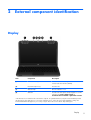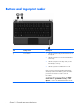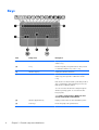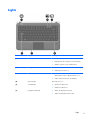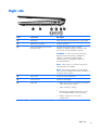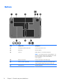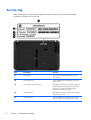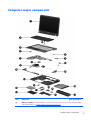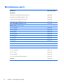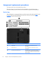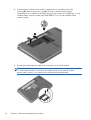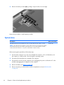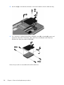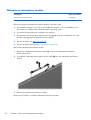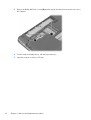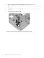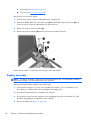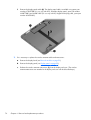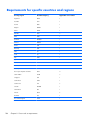
1
HP Pavilion dm4 Entertainment PC
Maintenance and Service Guide
© Copyright 2011 Hewlett-Packard
Development Company, L.P.
Bluetooth is a trademark owned by its
proprietor and used by Hewlett-Packard
Company under license. Intel and Core are
trademarks of Intel Corporation in the U.S.
and other countries. Microsoft, Windows,
and Windows Vista are U.S. registered
trademarks of Microsoft Corporation. SD
Logo is a trademark of its proprietor.
The information contained herein is subject
to change without notice. The only
warranties for HP products and services are
set forth in the express warranty statements
accompanying such products and services.
Nothing herein should be construed as
constituting an additional warranty. HP shall
not be liable for technical or editorial errors
or omissions contained herein.
Second Edition: December 2011
First Edition: November 2011
Document Part Number: 659982-002
Safety warning notice
WARNING! To reduce the possibility of heat-related injuries or of overheating the device, do not
place the device directly on your lap or obstruct the device air vents. Use the device only on a hard, flat
surface. Do not allow another hard surface, such as an adjoining optional printer, or a soft surface,
such as pillows or rugs or clothing, to block airflow. Also, do not allow the AC adapter to contact
the skin or a soft surface, such as pillows or rugs or clothing, during operation. The device and the AC
adapter comply with the user-accessible surface temperature limits defined by the International
Standard for Safety of Information Technology Equipment (IEC 60950).
iii
iv
Safety warning notice
Table of contents
1 Product description ........................................................................................................... 1
2 External component identification ..................................................................................... 5
Display ................................................................................................................................... 5
Buttons and fingerprint reader ................................................................................................... 6
Keys ....................................................................................................................................... 8
Lights ...................................................................................................................................... 9
TouchPad .............................................................................................................................. 10
Front ..................................................................................................................................... 11
Left side ................................................................................................................................ 12
Right side .............................................................................................................................. 13
Bottom .................................................................................................................................. 14
3 Illustrated parts catalog .................................................................................................. 15
Service tag ............................................................................................................................ 16
Computer major components ................................................................................................... 17
Display assembly subcomponents ............................................................................................. 22
Mass storage devices ............................................................................................................. 24
Plastics Kit ............................................................................................................................. 25
Miscellaneous parts ................................................................................................................ 26
Sequential part number listing .................................................................................................. 27
4 Removal and replacement procedures ............................................................................ 33
Preliminary replacement requirements ....................................................................................... 33
Tools required ......................................................................................................... 33
Service considerations ............................................................................................. 33
Plastic parts ............................................................................................. 33
Cables and connectors ............................................................................. 33
Drive handling ......................................................................................... 34
Grounding guidelines .............................................................................................. 34
Electrostatic discharge damage .................................................................. 34
v
Packaging and transporting guidelines ........................................ 36
Component replacement procedures ........................................................................................ 38
Service tag ............................................................................................................. 38
Battery ................................................................................................................... 39
WLAN module ........................................................................................................ 41
mSATA solid-state drive ............................................................................................ 44
Memory module ...................................................................................................... 45
Optical drive .......................................................................................................... 46
Hard drive ............................................................................................................. 48
RTC battery ............................................................................................................ 51
Bluetooth module .................................................................................................... 52
Webcamera/microphone module ............................................................................. 54
Display panel ......................................................................................................... 55
Keyboard ............................................................................................................... 57
Top cover ............................................................................................................... 60
Fingerprint reader board .......................................................................................... 65
Audio/USB board ................................................................................................... 67
Power button board ................................................................................................. 68
Power connector cable ............................................................................................ 69
Display assembly .................................................................................................... 70
System board ......................................................................................................... 76
Fan/heat sink assembly ........................................................................................... 79
Processor ............................................................................................................... 82
Speakers ................................................................................................................ 84
Optical drive connector cable ................................................................................... 86
Subwoofer ............................................................................................................. 88
5 Setup Utility (BIOS) and System Diagnostics .................................................................... 90
Using Setup Utility .................................................................................................................. 90
Starting Setup Utility ................................................................................................ 90
Changing the language of Setup Utility ...................................................................... 90
Navigating and selecting in Setup Utility .................................................................... 91
Displaying system information ................................................................................... 91
Restoring factory settings in Setup Utility ..................................................................... 92
Exiting Setup Utility ................................................................................................. 92
Updating the BIOS .................................................................................................. 92
Determining the BIOS version .................................................................... 93
Downloading a BIOS update ..................................................................... 93
Using System Diagnostics ........................................................................................................ 94
vi
6 Specifications ................................................................................................................. 95
Computer specifications .......................................................................................................... 95
14.0-in display specifications .................................................................................................. 96
Hard drive specifications ........................................................................................................ 97
7 Backup and recovery ...................................................................................................... 98
Restore ................................................................................................................................. 98
Creating restore media ........................................................................................................... 99
Performing a system restore ................................................................................................... 100
Using the dedicated recovery partition ..................................................................... 100
Restoring using the restore media ............................................................................ 101
Changing the computer boot order .......................................................................... 101
Backing up and recovering your information ........................................................................... 102
Using Windows Backup and Restore ....................................................................... 103
Using Windows system restore points ...................................................................... 103
When to create restore points .................................................................. 103
Create a system restore point ................................................................... 104
Restore to a previous date and time .......................................................... 104
8 Power cord set requirements ........................................................................................ 105
Requirements for all countries ................................................................................................ 105
Requirements for specific countries and regions ....................................................................... 106
9 Recycling ...................................................................................................................... 108
Index ............................................................................................................................... 109
vii
viii
1
Product description
Category
Description
Product Name
HP Pavilion dm4 Entertainment PC
Processors
Intel® Core® i7-2640M 2.80-GHz processor (SC turbo up to 3.40-GHz), 4.0-MB L3 cache, 1333MHz FSB, dual core, 35 W)
Intel Core i5-2540M 2.60-GHz processor (SC turbo up to 3.30-GHz), 3.0-MB L3 cache, 1333MHz FSB, dual core, 35 W)
Intel Core i5-2520M 2.50-GHz processor (SC turbo up to 3.20-GHz), 3.0-MB L3 cache, 1333MHz FSB, dual core, 35 W)
Intel Core i5-2430M 2.40-GHz processor (SC turbo up to 3.00-GHz), 3.0-MB L3 cache, 1333MHz FSB, dual core, 35 W)
Intel Core i3-2350M TJ85 2.30-GHz processor (3.0-MB L3 cache, 1333-MHz FSB, dual core,
35 W)
Chipset
Intel 6 series express chipset HM67 platform controller hub (PCH)
Graphics
Intel graphics: Intel HD Graphics 3000
Switchable discrete graphics: ATi XT Radeon HD7470 package with 1024-MB of graphics
subsystem discrete memory (64-MB × 32 GDDR5 × 4 PCs, 5GBPS), muxless
Support for BD playback with switchable graphics, BACO, HD decode, and DX11
Panel
●
14.0-in, high-definition+ (HD+), light-emitting diode (LED), AntiGlare (1600×900) SVA
display; typical brightness: 200 nits
●
14.0-in, high-definition (HD), light-emitting diode (LED), BrightView (1366×768) SVA display;
typical brightness: 200 nits
All display assemblies include 2 wireless local area network (WLAN) antenna cables
Supports 16:9 wide aspect ratio
Lighted logo on display enclosure
Memory
2 customer-accessible/upgradable memory module slots
DDR3-1333-MHz support
Supports up to 16384-GB of system RAM @ 1333-MHz
1
Category
Description
Supports the following configurations:
Hard drives
●
16384-MB total system memory (8192 × 2 @ 1333-MHz, not supported with 32-bit operating
system, available only in the United States)
●
12288-MB total system memory (8192 + 4096 @ 1333-MHz, not supported with 32-bit
operating system, available only in the United States)
●
8192-MB total system memory (8192×1 @ 1333-MHz, not supported with 32-bit operating
system, available only in the United States)
●
8192-MB total system memory (4096×2 @ 1333-MHz, not supported with 32-bit operating
system)
●
6144-MB total system memory (4096 + 2048 @ 1333-MHz, not supported with 32-bit
operating system)
●
4096-MB total system memory (4096×1 @ 1333-MHz, 2048×2 @ 1333-MHz)
●
2048-MB total system memory (2048×1 @ 1333-MHz)
Supports 6.35-cm (2.5-in) hard drives in 9.5-mm (.37-in) and 7.0-mm (.28-in) thicknesses
Customer-accessible
Serial ATA (SATA)
Supports Accelerometer hard drive protection
Supports a 20-GB mSATA solid-state drive
Supports the following hard drives:
●
1-TB, 5400-rpm, 9.5-mm
●
750-GB, 5400-rpm, 9.5-mm
●
640-GB, 5400-rpm, 9.5-mm
●
500-GB, 7200-rpm and 5400-rpm, 9.5-mm
●
320-GB, 7200-rpm and 5400-rpm, 9.5-mm
Supports either a 750-GB, 5400-rpm, 9.5-mm hard drive + 20-GB mSATA solid-state drive
combination configuration or a 500-GB, 7200-rpm, 9.5-mm hard drive + 20-GB mSATA solidstate drive combination configuration
Optical drive
Fixed
SATA
9.5-mm slot load
Supports DVD±RW Double-Layer FX SuperMulti Drive
Audio and video
2 digital, dual-array microphones with appropriate beam-forming, echo-cancellation, noisesuppression software
Supports Microsoft Premium requirements
Subwoofer
2
Chapter 1 Product description
Category
Description
Beats signature audio profile applied to both headphones and external speakers
HP TrueVision high-definition webcam with activity light (fixed, no tilt, 1280×720 by 24 frames
per second)
Ethernet
Integrated 10/100/1000 network interface controller (NIC)
Wireless
Integrated WLAN options by way of wireless module
Two WLAN antennas built into display assembly
Supports the following WLAN formats:
External media card
●
Atheros 9485GN 802.11b/g/n 1×1 WiFi and 3012 Bluetooth 4.0 Combo Adapter
●
Broadcom 4313 802.11b/g/n 1×1 WiFi and 2070 Bluetooth 2.1+EDR Combo adapter
(BT3.0+HS ready) for use only in Brazil
●
Broadcom 4313GN 802.11b/g/n 1×1 WiFi and 20702 Bluetooth 4.0 Combo Adapter
●
Intel Centrino Advanced-N 6230 WLAN module
●
Intel Centrino Ultimate-N 6300 WLAN module
●
Intel Centrino Wireless-N 2230 WLAN module
●
Intel Centrino Wireless-N + WiMAX 6150 WLAN module
Push-push insertion/removal
HP Multi-Format Digital Media Reader (push/push insertion and removal) supports the following
digital card formats:
Ports
Keyboard/pointing
devices
●
Secure Digital (SD) Memory Card
●
Secure Digital Extended Capacity (SDxC) Memory Card
●
Secure Digital High Capacity (SDHC) Memory Card
●
Ultra High Speed MultiMediaCard (UHS/MMC)
●
3-pin AC power
●
Audio-in (mono microphone)
●
Audio-out (stereo headphone)
●
VGA (Dsub 15 pin) supporting 2048×1536 external resolution @ 75 Hz, hot plug and unplug
and auto-detection for correct output to wide-aspect vs. standard aspect video
●
HDMI v1.4 supporting up to 1080p, 1920×1200 @ 60-Hz, DVI mode
●
RJ-45 (Ethernet)
●
USB 3.0 and USB 2.0 ports (3 ports, two USB 3.0 ports on the left side of the computer, one
USB 2.0 port on the right side of the computer)
Full-size Duracoat, island-style keyboard, in black finish (available only on non-Beats Edition
computer models)
Full-size Duracoat, backlit, island-style keyboard, in black finish (available only in the United States)
3
Category
Description
Full-size Duracoat, backlit, island-style keyboard, in red finish (available only on Beats Edition
computer models)
TouchPad with image sensor
TouchPad with gesture support enabled (HP-defined: scroll and pinch,)
Taps enabled as default
Power requirements
Supports the following AC adapters:
●
90-W HP Smart AC adapter (PFC/RC/V/EM 3-wire)
●
90-W HP Smart AC adapter (PFC/RC/V 3-wire)
●
65-W HP Smart AC adapter (RC/V/EM 3-wire)
●
65-W HP Smart AC adapter (RC/V 3-wire)
Supports the following batteries:
Security
Operating system
●
9-cell, 100-Wh, 3.00-Ah, Li-ion battery
●
6-cell, 62-Wh, 2.80-Ah, Li-ion battery
●
6-cell, 55-Wh, 2.55-Ah, Li-ion battery
●
Fingerprint reader
●
Intel AT-p Ready support
●
OTP (VeriSign) support
●
Security cable slot
Preinstalled:
●
Windows 7 Home Basic 64-bit
NOTE:
Serviceability
4
All Windows 7 64-bit operating systems require 2 GB of system memory.
●
Windows 7 Home Premium 64-bit
●
Windows 7 Professional 64-bit
●
Windows 7 Starter 64-bit (available only on computer models equipped with a 320-GB hard
drive)
End-user replaceable parts:
●
AC adapter
●
Battery
●
Hard drive
●
Memory modules (2)
●
mSATA solid-state drive
●
Optical drive
●
WLAN module
Chapter 1 Product description
2
External component identification
Display
Item
Component
Description
(1)
WLAN antennas (2)*
Send and receive wireless signals to communicate with
wireless local area networks (WLANs).
(2)
Internal microphones (2)
Record sound.
(3)
Webcam light
On: The webcam is in use.
(4)
Webcam
Records video and captures still photographs. To use the
webcam, select Start > All Programs >
Communication and Chat > CyberLink YouCam.
*The antennas are not visible from the outside of the computer. For optimal transmission, keep the areas immediately around
the antennas free from obstructions. To see wireless regulatory notices, refer to the section of the Regulatory, Safety, and
Environmental Notices that applies to your country or region. These notices are located in Help and Support.
Display
5
Buttons and fingerprint reader
Item
Component
Description
(1)
Power button
●
When the computer is off, press the button to turn on
the computer.
●
When the computer is on, press the button briefly to
initiate Sleep.
●
When the computer is in the Sleep state, press the
button briefly to exit Sleep.
●
When the computer is in Hibernation, press the
button briefly to exit Hibernation.
If the computer has stopped responding and Windows
shutdown procedures are ineffective, press and hold the
power button for at least 5 seconds to turn off
the computer.
To learn more about your power settings, select Start >
Control Panel > System and Security > Power
Options, or refer to the HP Notebook Reference Guide.
6
Chapter 2 External component identification
Item
Component
Description
(2)
QuickWeb button
Opens QuickWeb (select models only).
●
When the computer is off or in Hibernation, press
the button to open HP QuickWeb.
●
When the computer is in Microsoft Windows, press
the button to open the default Web browser.
●
When the computer is in HP QuickWeb, press the
button to open the Web browser.
QuickWeb allows you to browse the Internet,
communicate with Skype, and explore other HP
QuickWeb programs. When the computer is off or in
Hibernation, you can press the QuickWeb button to
access these features without waiting for the operating
system to start.
NOTE: For more information, refer to the HP
QuickWeb software Help. If your computer does not
have HP QuickWeb software, the button opens the
Web browser.
(3)
Fingerprint reader
Allows a fingerprint logon to Windows, instead of a
password logon.
Buttons and fingerprint reader
7
Keys
Item
Component
Description
(1)
esc key
Displays system information when pressed in combination
with the fn key.
(2)
fn key
Executes frequently used system functions when pressed
in combination with the b key or the esc key.
(3)
Windows logo key
Displays the Windows Start menu.
(4)
b key
Enables or disables the Beats Audio bass settings (select
models only) when pressed in combination with the
fn key.
Beats Audio is an enhanced audio profile that provides a
deep, controlled bass while maintaining a clear sound.
Beats Audio is enabled by default.
You can view and control the bass settings through the
Windows operating system. To view and control the
bass properties:
Select Start > Control Panel > Hardware and
Sound > Beats Audio Control Panel.
8
(5)
Windows applications key
Displays a shortcut menu for items beneath the pointer.
(6)
Action keys
Execute frequently used system functions.
Chapter 2 External component identification
Lights
Item
Component
Description
(1)
Power light
●
White: The computer is on.
●
Blinking white: The computer is in the Sleep state.
●
Off: The computer is off or in Hibernation.
●
Amber: Computer sound is off.
●
Off: Computer sound is on.
●
White: An integrated wireless device, such as a
WLAN device and/or a Bluetooth device, is on.
●
Amber: All wireless devices are disabled.
(2)
(3)
Mute light
Wireless light
(4)
Caps lock light
On: Caps lock is on.
(5)
TouchPad light
●
On: The TouchPad is off.
●
Off: The TouchPad is on.
●
White: The fingerprint was read.
●
Amber: The fingerprint was not read.
(6)
Fingerprint reader light
Lights
9
TouchPad
10
Item
Component
Description
(1)
TouchPad light
●
On: The TouchPad is off.
●
Off: The TouchPad is on.
(2)
TouchPad on/off button
Turns the TouchPad on or off.
(3)
TouchPad zone
Moves the pointer and selects or activates items on
the screen.
(4)
Left TouchPad button
Functions like the left button on an external mouse.
(5)
Right TouchPad button
Functions like the right button on an external mouse.
Chapter 2 External component identification
Front
Item
Component
Description
(1)
Digital Media Slot
Supports the following digital card formats:
(2)
Speakers (2)
●
Secure Digital (SD) Memory Card
●
Secure Digital Extended Capacity (SDxC)
Memory Card
●
Secure Digital High Capacity (SDHC) Memory Card
●
Ultra High Speed MultiMediaCard (UHS/MMC)
Produce sound.
Front
11
Left side
Item
Component
Description
(1)
Security cable slot
Attaches an optional security cable to the computer.
NOTE: The security cable is designed to act as a
deterrent, but it may not prevent the computer from being
mishandled or stolen.
(2)
Vent
Enables airflow to cool internal components.
NOTE: The computer fan starts up automatically to cool
internal components and prevent overheating. It is normal
for the internal fan to cycle on and off during
routine operation.
(3)
(4)
Power light
Hard drive light
●
White: The computer is on.
●
Blinking white: The computer is in the Sleep state.
●
Off: The computer is off or in Hibernation.
●
Blinking white: The hard drive is being accessed.
●
Amber: HP 3D DriveGuard has temporarily parked
the hard drive.
NOTE: For information on HP ProtectSmart Hard
Drive Protection, refer to the HP Notebook
Reference Guide.
(5)
External monitor port
Connects an external VGA monitor or projector.
(6)
RJ-45 (network) jack
Connects a network cable.
(7)
HDMI port
Connects an optional video or audio device, such as a
high-definition television, or any compatible digital or
audio device.
(8)
USB 3.0 ports (2)
Connect optional USB 3.0 devices and provide
enhanced USB power performance.
NOTE: The USB 3.0 ports are also compatible with
USB 1.0 and 2.0 devices.
12
Chapter 2 External component identification
Right side
Item
Component
Description
(1)
Optical drive
Reads and writes (select models only) to an optical disc.
(2)
Optical drive eject button
Ejects the optical disc.
(3)
Audio-out (headphone) jack/audio-in
(microphone) jack
Connects optional powered stereo speakers,
headphones, earbuds, a headset, or television audio.
Also connects an optional headset microphone.
WARNING! To reduce the risk of personal injury,
adjust the volume before putting on headphones,
earbuds, or a headset. For additional safety
information, refer to the Regulatory, Safety, and
Environmental Notices.
NOTE: When a device is connected to the jack, the
computer speakers are disabled.
NOTE: The microphone function is operational only
when used with a headphone/microphone unit that has a
4-conductor audio connector.
(4)
USB 2.0 port
Connects an optional USB device.
(5)
Power connector
Connects an AC adapter.
(6)
Battery light
●
White: The computer is connected to external power
and the battery is fully charged.
●
Amber: A battery is charging.
●
Blinking white: The battery charge level is 12% or
less (recharge the battery as soon as possible).
●
Off: The computer is not connected to
external power.
Right side
13
Bottom
Item
Component
Description
(1)
HP Triple Bass Reflex Subwoofers
Provide superior bass sound.
(2)
Battery bay
Holds the battery.
(3)
Vents (3)
Enable airflow to cool internal components.
NOTE: The computer fan starts up automatically to cool
internal components and prevent overheating. It is normal
for the internal fan to cycle on and off during
routine operation.
14
(4)
Battery release latch
Releases the battery from the battery bay..
(5)
Memory module compartment
Contains the memory module slots, the WLAN module,
and the mSATA solid-state drive (select models only).
(6)
Hard drive bay
Holds the hard drive.
Chapter 2 External component identification
3
Illustrated parts catalog
15
Service tag
When ordering parts or requesting information, provide the computer serial number and model
description provided on the service tag.
16
Item
Description
Function
(1)
Product name
This is the product name affixed to the front of
the computer.
(2)
Serial number (s/n)
This is an alphanumeric identifier that is unique to
each product.
(3)
Part number/Product number (p/n)
This number provides specific information about the
product's hardware components. The part number
helps a service technician to determine what
components and parts are needed.
(4)
Warranty period
This number describes the duration of the warranty
period for the computer.
(5)
Model description
This is the alphanumeric identifier used to locate
documents, drivers, and support for the computer.
Chapter 3 Illustrated parts catalog
Computer major components
Item
Component
Spare part number
(1)
Display assembly: The display assembly is spared at the subcomponent level only. For more display assembly
spare part information, see Display assembly subcomponents on page 22.
Computer major components
17
Item
Component
(2)
Keyboard (includes keyboard cable):
Spare part number
For use only with Beats Edition computer models:
For use in Brazil
669069-201
For use in Canada
669069-121
For use in Denmark, Finland, Norway
669069-DH1
For use in France
669069-051
For use in Germany
669069-041
For use in India
669069-D61
For use in Japan
669069-291
For use in Latin America
669069-161
For use in the Netherlands
669069-B31
For use in Russia
669069-251
For use in Saudi Arabia
669069-171
For use in South Korea
669069-AD1
For use in Spain
669069-071
For use in Switzerland
665917-BG1
For use in Taiwan
665917-AB1
For use in Thailand
665917-281
For use in Turkey
665917-141
For use in the United Kingdom and Singapore
665917-031
For use in the United States
665917-001
Keyboard without backlight for use only on non-Beat Edition computer models
669070-001
Keyboard with backlight (includes backlight):
18
For use in Brazil
671180-201
For use in Canada
671180-121
For use in Denmark, Finland, Norway
671180-DH1
For use in France
671180-051
For use in Germany
671180-041
For use in Italy
671180-061
For use in Japan
671180-291
For use in Latin America
671180-161
For use in the Netherlands
671180-B31
Chapter 3 Illustrated parts catalog
Item
(3)
Component
Spare part number
For use in Portugal
671180-131
For use in Russia
671180-251
For use in Saudi Arabia
671180-171
For use in South Korea
671180-AD1
For use in Spain
671180-071
For use in Switzerland
671180-BG1
For use in Taiwan
671180-AB1
For use in Turkey
671180-141
For use in the United Kingdom and Singapore
671180-031
For use in the United States
671180-001
Top cover (includes TouchPad, but does not include TouchPad cables):
NOTE:
The TouchPad cables are included in the Cable Kit, spare part number 669062-001.
For use only with Beats Edition computer models
669932-001
In dark umber finish
669930-001
In steel gray finish
669931-001
(4)
Power button board (includes cable)
669072-001
(5)
Fingerprint reader board (includes bracket, does not include cable)
669064-001
NOTE: The fingerprint reader board cable is included in the Cable Kit, spare part
number 669062-001.
(6)
Audio/USB board (does not include cable)
669073-001
NOTE: The audio/USB board is included in the Cable Kit, spare part number
669062-001.
(7)
(8)
System board (includes processor and replacement thermal material):
For use only with computer models equipped with the Intel 7570 chipset and a
graphics subsystem with discrete memory
676577-001
For use only with computer models equipped with the Intel 6490 chipset and a
graphics subsystem with discrete memory
669084-001
For use only with computer models equipped with a graphics subsystem with
UMA memory
669085-001
Thermal Material Kit (not illustrated, includes replacement thermal paste and
thermal pads)
669929-001
Intel Core processor (includes replacement thermal material):
Intel Core i7-2640M 2.80-GHz processor (SC turbo up to 3.40-GHz), 4.0-MB L3
cache, 1333-MHz FSB, dual core, 35 W)
666173-001
Intel Core i5-2540M 2.60-GHz processor (SC turbo up to 3.30-GHz), 3.0-MB L3
cache, 1333-MHz FSB, dual core, 35 W)
631255-001
Computer major components
19
Item
Component
Spare part number
Intel Core i5-2520M 2.50-GHz processor (SC turbo up to 3.20-GHz), 3.0-MB L3
cache, 1333-MHz FSB, dual core, 35 W)
631253-001
Intel Core i5-2430M 2.40-GHz processor (SC turbo up to 3.00-GHz), 3.0-MB L3
cache, 1333-MHz FSB, dual core, 35 W)
653341-001
Intel Core i3-2350M TJ85 2.30-GHz processor (3.0-MB L3 cache, 1333-MHz FSB,
dual core, 35 W)
653340-001
Plastics Kit
NOTE:
See Plastics Kit on page 25 for more Plastics Kit spare part information.
For use only with Beats Edition computer models
671170-001
For use only with non-Beats Edition computer models
669075-001
Includes:
(9a)
Hard drive cover (includes one captive screw, secured by a C-clip)
(9b)
Memory module/wireless module compartment cover (includes one captive screw, secured by a C-clip)
(10)
Power connector cable (includes bracket)
(11)
Fan/heat sink assembly (includes replacement thermal material)
669063-001
For use only with computer models equipped with a graphics subsystem with
discrete memory
669934-001
For use only with computer models equipped with a graphics subsystem with
UMA memory
669935-001
(12)
Speakers (include left and right speakers, cables, and rubber isolator)
669933-001
(13)
Subwoofer (includes cable and rubber isolators)
670733-001
(14)
Base enclosure (includes rubber feet):
(15)
For use only with Beats Edition computer models
670729-001
For use only with non-Beats Edition computer models
669059-001
Rubber Kit (includes base enclosure rubber feet and rubber screw covers)
669079-001
Hard drive (does not include hard drive bracket, cable, or screws):
NOTE: The hard drive bracket, cable, and screws are included in the Hard Drive Hardware Kit, spare part
number 669066-001.
20
1-TB, 5400-rpm, 9.5-mm
676521-001
750-GB, 5400-rpm, 9.5-mm
634250-001
640-GB, 5400-rpm, 9.5-mm
669300-001
500-GB, 7200-rpm, 9.5-mm
634925-001
500-GB, 5400-rpm, 9.5-mm
669299-001
320-GB, 7200-rpm, 9.5-mm
634862-001
320-GB, 7200-rpm, 7.0-mm
641672-001
Chapter 3 Illustrated parts catalog
Item
Component
Spare part number
320-GB, 5400-rpm, 7.0-mm
645193-001
(16)
RTC battery (includes cable)
619451-001
(17)
Memory modules (2):
PC3, 10600, 1333-MHz
8 MB
634091-001
4 GB
621569-001
2 GB
621565-001
(18)
20-GB mSATA solid-state drive
669082-001
(19)
WLAN module:
(20)
Atheros 9485GN 802.11b/g/n 1×1 WiFi and 3012 Bluetooth 4.0 Combo Adapter
655795-001
Broadcom 4313 802.11b/g/n 1×1 WiFi and 2070 Bluetooth 2.1+EDR Combo
adapter (BT3.0+HS ready) for use only in Brazil
600370-201
Broadcom 4313GN 802.11b/g/n 1×1 WiFi and 20702 Bluetooth 4.0
Combo Adapter
657325-001
Intel Centrino Advanced-N 6230 WLAN module
631956-001
Intel Centrino Ultimate-N 6300 WLAN module
572511-001
Intel Centrino Wireless-N 2230 WLAN module
670290-001
Intel Centrino Wireless-N + WiMAX 6150 WLAN module
633817-001
DVD±RW Double-Layer FX SuperMulti Drive (does not include bezel,
bracket, cable, or screws)
669071-001
NOTE: The optical drive bezel, bracket, cable, and screws are included in the
Optical Drive Hardware Kit, spare part numbers 670734-001 (for use only with Beats
Edition computer models) and 670735-001 (for use only with non-Beats Edition
computer models).
(21)
Battery:
9-cell, 100-Wh, 3.00-Ah, Li-ion battery
636631-001
6-cell, 62-Wh, 2.80-Ah, Li-ion battery
593562-001
6-cell, 55-Wh, 2.55-Ah, Li-ion battery
593554-001
Computer major components
21
Display assembly subcomponents
Item
Component
(1)
Display bezel:
For use only with Beats Edition computer models
670730-001
For use only with non-Beats Edition computer models
669060-001
(2)
Bluetooth module, 4.0 EDR
655792-001
(3)
Webcamera/microphone module
669086-001
(4)
Display panel cable (includes Bluetooth module cable and webcamera module cable):
(5)
(6)
For use only with HD+, AntiGlare display panel, spare part number 669077-001
670397-001
For use only with HD, BrightView display panel, spare part number 669076-001
669061-001
Display hinge covers (includes left and right hinge covers):
For use only with Beats Edition computer models
670732-001
For use only with non-Beats Edition computer models
669068-001
Display panel:
14.0-in, HD+, LED, SVA AntiGlare display panel
22
Spare part number
Chapter 3 Illustrated parts catalog
669077-001
Item
Component
Spare part number
14.0-in, HD, LED, SVA BrightView display panel
669076-001
(7)
Wireless Antenna Kit (includes left and right wireless antenna cables
and transceivers)
669055-001
(8)
Display Hinge Kit
670731-001
(9)
Display enclosure:
For use only with Beats Edition computer models
669058-001
In dark umber finish
669056-001
In steel gray finish
669057-001
Display Screw Kit (not illustrated)
669080-001
Display assembly subcomponents
23
Mass storage devices
Item
Component
(1)
Hard drive (does not include hard drive bracket, cable, or screws):
Spare part number
1-TB, 5400-rpm, 9.5-mm
676521-001
750-GB, 5400-rpm, 9.5-mm
634250-001
640-GB, 5400-rpm, 9.5-mm
669300-001
500-GB, 7200-rpm, 9.5-mm
634925-001
500-GB, 5400-rpm, 9.5-mm
669299-001
320-GB, 7200-rpm, 9.5-mm
634862-001
320-GB, 7200-rpm, 7.0-mm
641672-001
320-GB, 5400-rpm, 7.0-mm
645193-001
Hard Drive Hardware Kit, includes:
669066-001
(2a)
Hard drive bracket
(2b)
Hard drive cable
Hard drive screws (not illustrated)
(3)
DVD±RW Double-Layer FX SuperMulti Drive (does not include bezel,
bracket, cable, or screws):
669071-001
Optical Drive Hardware Kit:
For use only with Beats Edition computer models
670734-001
For use only with non-Beats Edition computer models
670735-001
Includes:
(4a)
24
Optical drive bezel
Chapter 3 Illustrated parts catalog
Item
Component
(4b)
Optical drive bracket
(4c)
Optical drive connector cable
Spare part number
Optical drive screws (not illustrated)
(5)
20-GB mSATA solid-state drive
669082-001
Plastics Kit
Item
Component
Spare part number
Plastics Kit
For use only with Beats Edition computer models
671170-001
For use only with non-Beats Edition computer models
669075-001
Includes:
(1)
Memory module/wireless module compartment cover (includes one captive screw, secured by a C-clip)
(2)
Hard drive cover (includes one captive screw, secured by a C-clip)
Plastics Kit
25
Miscellaneous parts
Component
Spare part number
AC adapter:
90-W HP Smart AC adapter (PFC/RC/V/EM 3-wire)
609947-001
90-W HP Smart AC adapter (PFC/RC/V 3-wire)
609940-001
65-W HP Smart AC adapter (RC/V/EM 3-wire)
609948-001
65-W HP Smart AC adapter (RC/V 3-wire)
609939-001
14-in. Beats Edition protective cover
667666-001
Power cord (3-pin, black, 1.83-m):
26
For use in Argentina
490371-D01
For use in Australia
490371-011
For use in Brazil
490371-202
For use in Denmark
490371-081
For use in Europe
490371-021
For use in India
490371-D61
For use in Italy
490371-061
For use in Japan
490371-291
For use in North America
490371-001
For use in the People's Republic of China
490371-AA1
For use in South Korea
490371-AD1
For use in Switzerland
490371-111
For use in Taiwan
490371-AB1
For use in Thailand
490371-201
For use in the United Kingdom and Singapore
490371-031
Screw Kit
669081-001
Chapter 3 Illustrated parts catalog
Sequential part number listing
Spare part
number
Description
490371-001
Power cord for use in North America (3-pin, black, 1.83-m)
490371-011
Power cord for use in Australia (3-pin, black, 1.83-m)
490371-021
Power cord for use in Europe (3-pin, black, 1.83-m)
490371-031
Power cord for use in the United Kingdom and Singapore (3-pin, black, 1.83-m)
490371-061
Power cord for use in Italy (3-pin, black, 1.83-m)
490371-081
Power cord for use in Denmark (3-pin, black, 1.83-m)
490371-111
Power cord for use in Switzerland (3-pin, black, 1.83-m)
490371-201
Power cord for use in Thailand (3-pin, black, 1.83-m)
490371-202
Power cord for use in Brazil (3-pin, black, 1.83-m)
490371-291
Power cord for use in Japan (3-pin, black, 1.83-m)
490371-AA1
Power cord for use in the People's Republic of China (3-pin, black, 1.83-m)
490371-AB1
Power cord for use in Taiwan (3-pin, black, 1.83-m)
490371-AD1
Power cord for use in South Korea (3-pin, black, 1.83-m)
490371-D01
Power cord for use in Argentina (3-pin, black, 1.83-m)
490371-D61
Power cord for use in India (3-pin, black, 1.83-m)
572511-001
Intel Centrino Ultimate-N 6300 WLAN module
593554-001
6-cell, 55-Wh, 2.55-Ah, Li-ion battery
593562-001
6-cell, 62-Wh, 2.80-Ah, Li-ion battery
600370-201
Broadcom 4313 802.11b/g/n 1×1 WiFi and 2070 Bluetooth 2.1+EDR Combo adapter
(BT3.0+HS ready) for use only in Brazil
609939-001
65-W HP Smart AC adapter (RC/V 3-wire)
609940-001
90-W HP Smart AC adapter (PFC/RC/V 3-wire)
609947-001
90-W HP Smart AC adapter (PFC/RC/V/EM 3-wire)
609948-001
65-W HP Smart AC adapter (RC/V/EM 3-wire)
619451-001
RTC battery
621565-001
2-GB memory module (PC3, 10600, 1333-MHz)
621569-001
4-GB memory module (PC3, 10600, 1333-MHz)
631253-001
Intel Core i5-2520M 2.50-GHz processor (SC turbo up to 3.20-GHz), 3.0-MB L3 cache, 1333-MHz FSB,
dual core, 35 W (includes replacement thermal material)
631255-001
Intel Core i5-2540M 2.60-GHz processor (SC turbo up to 3.30-GHz), 3.0-MB L3 cache, 1333-MHz FSB,
dual core, 35 W (includes replacement thermal material)
Sequential part number listing
27
Spare part
number
Description
631956-001
Intel Centrino Advanced-N 6230 WLAN module
633817-001
Intel Centrino Wireless-N + WiMAX 6150 WLAN module
634091-001
8-GB memory module (PC3, 10600, 1333-MHz)
634250-001
750-GB, 5400-rpm, 9.5-mm hard drive (does not include bracket, cable, or screws)
NOTE: The hard drive bracket, cable, and screws are included in the Hard Drive Hardware Kit, spare
part number 669066-001.
634862-001
320-GB, 7200-rpm, 9.5-mm hard drive (does not include bracket, cable, or screws)
NOTE: The hard drive bracket, cable, and screws are included in the Hard Drive Hardware Kit, spare
part number 669066-001.
634925-001
500-GB, 7200-rpm, 9.5-mm hard drive (does not include bracket, cable, or screws)
NOTE: The hard drive bracket, cable, and screws are included in the Hard Drive Hardware Kit, spare
part number 669066-001.
636631-001
9-cell, 100-Wh, 3.00-Ah, Li-ion battery
641672-001
320-GB, 7200-rpm, 7.0-mm hard drive (does not include bracket, cable, or screws)
NOTE: The hard drive bracket, cable, and screws are included in the Hard Drive Hardware Kit, spare
part number 669066-001.
645193-001
320-GB, 5400-rpm, 7.0-mm hard drive (does not include bracket, cable, or screws)
NOTE: The hard drive bracket, cable, and screws are included in the Hard Drive Hardware Kit, spare
part number 669066-001.
28
653340-001
Intel Core i3-2350M TJ85 2.30-GHz processor (3.0-MB L3 cache, 1333-MHz FSB, dual core, 35 W;
includes replacement thermal material)
653341-001
Intel Core i5-2430M 2.40-GHz processor (SC turbo up to 3.00-GHz), 3.0-MB L3 cache, 1333-MHz FSB,
dual core, 35 W; includes replacement thermal material)
655792-001
Bluetooth module, 4.0 EDR
655795-001
Atheros 9485GN 802.11b/g/n 1×1 WiFi and 3012 Bluetooth 4.0 Combo Adapter
657325-001
Broadcom 4313GN 802.11b/g/n 1×1 WiFi and 20702 Bluetooth 4.0 Combo Adapter
666173-001
Intel Core i7-2640M 2.80-GHz processor (SC turbo up to 3.40-GHz), 4.0-MB L3 cache, 1333-MHz FSB,
dual core, 35 W; includes replacement thermal material)
667666-001
HP Beats Edition 14-in protective cover
669055-001
Wireless Antenna Kit (includes left and right wireless antenna cables and transceivers)
669056-001
Display enclosure in dark umber finish
669057-001
Display enclosure in steel gray finish
669058-001
Display enclosure for use only with Beats Edition computer models
669059-001
Base enclosure for use only with non-Beats Edition computer models
669060-001
Display bezel for use only with non-Beats Edition computer models
Chapter 3 Illustrated parts catalog
Spare part
number
Description
669061-001
Display Cable Kit for use only with HD, BrightView display panel, spare part number 669076-001
(includes Bluetooth module cable and webcamera cable)
669062-001
Cable Kit (includes audio/USB board cable, fingerprint reader board cable, and TouchPad board cables)
669063-001
Power connector cable (includes bracket)
669064-001
Fingerprint reader board (includes bracket, does not include cable)
NOTE: The fingerprint reader board spare part kit does not include the fingerprint reader board cable.
The fingerprint reader board cable is included in the Cable Kit, spare part number 669062-001.
669066-001
Hard Drive Hardware Kit (includes bracket, cable, and screws)
669068-001
Display hinge covers for use only with non-Beats Edition computer models (includes left and right
hinge covers)
669069-001
Keyboard for use with Beats Edition computer models in the United States (includes keyboard cable and
keyboard backlight cable)
669069-031
Keyboard for use with Beats Edition computer models in the United Kingdom and Singapore (includes
keyboard cable)
669069-041
Keyboard for use with Beats Edition computer models in Germany (includes keyboard cable)
669069-051
Keyboard for use with Beats Edition computer models in France (includes keyboard cable)
669069-071
Keyboard for use with Beats Edition computer models in Spain (includes keyboard cable)
669069-121
Keyboard for use with Beats Edition computer models in Canada (includes keyboard cable)
669069-141
Keyboard for use with Beats Edition computer models in Turkey (includes keyboard cable)
669069-161
Keyboard for use with Beats Edition computer models in Latin America (includes keyboard cable)
669069-171
Keyboard for use with Beats Edition computer models in Saudi Arabia (includes keyboard cable)
669069-201
Keyboard for use with Beats Edition computer models in Brazil (includes keyboard cable)
669069-251
Keyboard for use with Beats Edition computer models in Russia (includes keyboard cable)
669069-281
Keyboard for use with Beats Edition computer models in Thailand (includes keyboard cable)
669069-291
Keyboard for use with Beats Edition computer models in Japan (includes keyboard cable)
669069-AB1
Keyboard for use with Beats Edition computer models in Taiwan (includes keyboard cable)
669069-AD1
Keyboard for use with Beats Edition computer models in South Korea (includes keyboard cable)
669069-B31
Keyboard for use with Beats Edition computer models in the Netherlands (includes keyboard cable)
669069-BG1
Keyboard for use with Beats Edition computer models in Switzerland (includes keyboard cable)
669069-D61
Keyboard for use with Beats Edition computer models in India (includes keyboard cable)
669069-DH1
Keyboard for use with Beats Edition computer models in Denmark, Finland, and Norway (includes
keyboard cable)
669070-001
Keyboard without backlight for use only with non-Beats Edition computer models in the United States
(includes keyboard cable and keyboard backlight cable)
669071-001
DVD±RW Double-Layer FX SuperMulti Drive (does not include bezel, bracket, or screws)
Sequential part number listing
29
Spare part
number
Description
669072-001
Power button board (includes cable)
669073-001
Audio/USB board (does not include cable)
NOTE: The audio/USB board spare part kit does not include the audio/USB board cable. The audio/
USB board cable is included in the Cable Kit, spare part number 669062-001.
669075-001
Plastics Kit for use only with non-Beats Edition computer models (includes hard drive cover and memory
module/wireless module compartment cover)
669076-001
14.0-in, HD, LED, SVA BrightView display panel
669077-001
14.0-in, HD+, LED, SVA AntiGlare display panel
669079-001
Rubber Kit (includes base enclosure rubber feet and rubber screw covers)
669080-001
Display Screw Kit
669081-001
Screw Kit
669082-001
20-GB mSATA solid-state drive
669084-001
System board for use only with computer models equipped with the Intel 6490 chipset and a graphics
subsystem with discrete memory (includes replacement thermal material)
669085-001
System board for use only with computer models equipped with a graphics subsystem with UMA memory
(includes replacement thermal material)
669086-001
Webcamera/microphone module
669299-001
500-GB, 5400-rpm, 7.0-mm hard drive (does not include bracket, cable, or screws)
NOTE: The hard drive bracket, cable, and screws are included in the Hard Drive Hardware Kit, spare
part number 669066-001.
669300-001
640-GB, 5400-rpm, 9.5-mm hard drive (does not include bracket, cable, or screws)
NOTE: The hard drive bracket, cable, and screws are included in the Hard Drive Hardware Kit, spare
part number 669066-001.
669929-001
Thermal Material Kit (includes replacement thermal pads and paste)
669930-001
Top cover in dark umber finish (includes TouchPad, but does not include TouchPad cables)
NOTE: The top cover spare part kit does not include the TouchPad cables. The TouchPad cables are
included in the Cable Kit, spare part number 669062-001.
669931-001
Top cover in steel gray finish (includes TouchPad, but does not include TouchPad cables)
NOTE: The top cover spare part kit does not include the TouchPad cables. The TouchPad cables are
included in the Cable Kit, spare part number 669062-001.
669932-001
Top cover for use only with Beats Edition computer models (includes TouchPad, but does not include
TouchPad cables)
NOTE: The top cover spare part kit does not include the TouchPad cables. The TouchPad cables are
included in the Cable Kit, spare part number 669062-001.
669933-001
30
Speakers (include left and right speakers and cables)
Chapter 3 Illustrated parts catalog
Spare part
number
Description
669934-001
Fan/heat sink assembly for use only with computer models equipped with a graphics subsystem with
discrete memory (includes replacement thermal material)
669935-001
Fan/heat sink assembly for use only with computer models equipped with a graphics subsystem with UMA
memory (includes replacement thermal material)
670290-001
Intel Centrino Wireless-N 2230 WLAN module
670397-001
Display Cable Kit for use only with HD+, AntiGlare display panel, spare part number 669077-001
(includes Bluetooth module cable and webcamera cable)
670729-001
Base enclosure for use only with Beats Edition computer models
670730-001
Display bezel for use only with Beats Edition computer models
670731-001
Display Hinge Kit (includes left and right display hinges and brackets)
670732-001
Display hinge covers for use only with Beats Edition computer models (includes left and right hinge covers)
670733-001
Subwoofer (includes cable and rubber isolators)
670734-001
Optical Drive Hardware Kit for use only with non-Beats Edition computer models (includes optical drive
bezel, bracket, connector cable, and screws)
670735-001
Optical Drive Hardware Kit for use only with Beats Edition computer models (includes optical drive bezel,
bracket, connector cable, and screws)
671170-001
Plastics Kit for use only with Beats Edition computer models (includes hard drive cover and memory
module/wireless module compartment cover)
671180-001
Keyboard with backlight for use in the United States (includes keyboard cable and keyboard
backlight cable)
671180-031
Keyboard with backlight for use in the United Kingdom and Singapore (includes keyboard cable and
keyboard backlight cable)
671180-041
Keyboard with backlight for use in Germany (includes keyboard cable and keyboard backlight cable)
671180-051
Keyboard with backlight for use in France (includes keyboard cable and keyboard backlight cable)
671180-061
Keyboard with backlight for use in Italy (includes keyboard cable and keyboard backlight cable)
671180-071
Keyboard with backlight for use in Spain (includes keyboard cable and keyboard backlight cable)
671180-121
Keyboard with backlight for use in Canada (includes keyboard cable and keyboard backlight cable)
671180-131
Keyboard with backlight for use in Portugal (includes keyboard cable and keyboard backlight cable)
671180-141
Keyboard with backlight for use in Turkey (includes keyboard cable and keyboard backlight cable)
671180-161
Keyboard with backlight for use in Latin America (includes keyboard cable and keyboard backlight cable)
671180-171
Keyboard with backlight for use in Saudi Arabia (includes keyboard cable and keyboard backlight cable)
671180-201
Keyboard with backlight for use in Brazil (includes keyboard cable and keyboard backlight cable)
671180-251
Keyboard with backlight for use in Russia (includes keyboard cable and keyboard backlight cable)
671180-AB1
Keyboard with backlight for use in Taiwan (includes keyboard cable and keyboard backlight cable)
671180-AD1
Keyboard with backlight for use in South Korea (includes keyboard cable and keyboard backlight cable)
Sequential part number listing
31
Spare part
number
Description
671180-B31
Keyboard with backlight for use in the Netherlands (includes keyboard cable and keyboard
backlight cable)
671180-BG1
Keyboard with backlight for use in Switzerland (includes keyboard cable and keyboard backlight cable)
671180-DH1
Keyboard with backlight for use in Denmark, Finland, and Norway (includes keyboard cable and
keyboard backlight cable)
676521-001
1-TB, 5400-rpm, 9.5-mm hard drive (does not include bracket, cable, or screws)
NOTE: The hard drive bracket, cable, and screws are included in the Hard Drive Hardware Kit, spare
part number 669066-001.
676577-001
32
System board for use only with computer models equipped with the Intel 7570 chipset and a graphics
subsystem with discrete memory (includes replacement thermal material)
Chapter 3 Illustrated parts catalog
4
Removal and replacement
procedures
Preliminary replacement requirements
Tools required
You will need the following tools to complete the removal and replacement procedures:
●
Flat-bladed screwdriver
●
Magnetic screwdriver
●
Phillips P0 and P1 screwdrivers
Service considerations
The following sections include some of the considerations that you must keep in mind during
disassembly and assembly procedures.
NOTE: As you remove each subassembly from the computer, place the subassembly (and all
accompanying screws) away from the work area to prevent damage.
Plastic parts
CAUTION: Using excessive force during disassembly and reassembly can damage plastic parts. Use
care when handling the plastic parts. Apply pressure only at the points designated in the
maintenance instructions.
Cables and connectors
CAUTION: When servicing the computer, be sure that cables are placed in their proper locations
during the reassembly process. Improper cable placement can damage the computer.
Cables must be handled with extreme care to avoid damage. Apply only the tension required to unseat
or seat the cables during removal and insertion. Handle cables by the connector whenever possible. In
all cases, avoid bending, twisting, or tearing cables. Be sure that cables are routed in such a way that
they cannot be caught or snagged by parts being removed or replaced. Handle flex cables with
extreme care; these cables tear easily.
Preliminary replacement requirements
33
Drive handling
CAUTION: Drives are fragile components that must be handled with care. To prevent damage to
the computer, damage to a drive, or loss of information, observe these precautions:
Before removing or inserting a hard drive, shut down the computer. If you are unsure whether
the computer is off or in Hibernation, turn the computer on, and then shut it down through the
operating system.
Before handling a drive, be sure that you are discharged of static electricity. While handling a drive,
avoid touching the connector.
Before removing a diskette drive or optical drive, be sure that a diskette or disc is not in the drive and
be sure that the optical drive tray is closed.
Handle drives on surfaces covered with at least one inch of shock-proof foam.
Avoid dropping drives from any height onto any surface.
After removing a hard drive, an optical drive, or a diskette drive, place it in a static-proof bag.
Avoid exposing an internal hard drive to products that have magnetic fields, such as monitors
or speakers.
Avoid exposing a drive to temperature extremes or liquids.
If a drive must be mailed, place the drive in a bubble pack mailer or other suitable form of protective
packaging and label the package “FRAGILE.”
Grounding guidelines
Electrostatic discharge damage
Electronic components are sensitive to electrostatic discharge (ESD). Circuitry design and structure
determine the degree of sensitivity. Networks built into many integrated circuits provide some
protection, but in many cases, ESD contains enough power to alter device parameters or melt
silicon junctions.
A discharge of static electricity from a finger or other conductor can destroy static-sensitive devices or
microcircuitry. Even if the spark is neither felt nor heard, damage may have occurred.
An electronic device exposed to ESD may not be affected at all and can work perfectly throughout a
normal cycle. Or the device may function normally for a while, then degrade in the internal layers,
reducing its life expectancy.
34
Chapter 4 Removal and replacement procedures
CAUTION: To prevent damage to the computer when you are removing or installing internal
components, observe these precautions:
Keep components in their electrostatic-safe containers until you are ready to install them.
Before touching an electronic component, discharge static electricity by using the guidelines described
in this section.
Avoid touching pins, leads, and circuitry. Handle electronic components as little as possible.
If you remove a component, place it in an electrostatic-safe container.
The following table shows how humidity affects the electrostatic voltage levels generated by
different activities.
CAUTION: A product can be degraded by as little as 700 V.
Typical electrostatic voltage levels
Relative humidity
Event
10%
40%
55%
Walking across carpet
35,000 V
15,000 V
7,500 V
Walking across vinyl floor
12,000 V
5,000 V
3,000 V
Motions of bench worker
6,000 V
800 V
400 V
Removing DIPS from plastic tube
2,000 V
700 V
400 V
Removing DIPS from vinyl tray
11,500 V
4,000 V
2,000 V
Removing DIPS from Styrofoam
14,500 V
5,000 V
3,500 V
Removing bubble pack from PCB
26,500 V
20,000 V
7,000 V
Packing PCBs in foam-lined box
21,000 V
11,000 V
5,000 V
Preliminary replacement requirements
35
Packaging and transporting guidelines
Follow these grounding guidelines when packaging and transporting equipment:
●
To avoid hand contact, transport products in static-safe tubes, bags, or boxes.
●
Protect ESD-sensitive parts and assemblies with conductive or approved containers or packaging.
●
Keep ESD-sensitive parts in their containers until the parts arrive at static-free workstations.
●
Place items on a grounded surface before removing items from their containers.
●
Always be properly grounded when touching a component or assembly.
●
Store reusable ESD-sensitive parts from assemblies in protective packaging or
nonconductive foam.
●
Use transporters and conveyors made of antistatic belts and roller bushings. Be sure that
mechanized equipment used for moving materials is wired to ground and that proper materials
are selected to avoid static charging. When grounding is not possible, use an ionizer to dissipate
electric charges.
Workstation guidelines
Follow these grounding workstation guidelines:
36
●
Cover the workstation with approved static-shielding material.
●
Use a wrist strap connected to a properly grounded work surface and use properly grounded tools
and equipment.
●
Use conductive field service tools, such as cutters, screwdrivers, and vacuums.
●
When fixtures must directly contact dissipative surfaces, use fixtures made only of staticsafe materials.
●
Keep the work area free of nonconductive materials, such as ordinary plastic assembly aids
and Styrofoam.
●
Handle ESD-sensitive components, parts, and assemblies by the case or PCM laminate. Handle
these items only at static-free workstations.
●
Avoid contact with pins, leads, or circuitry.
●
Turn off power and input signals before inserting or removing connectors or test equipment.
Chapter 4 Removal and replacement procedures
Equipment guidelines
Grounding equipment must include either a wrist strap or a foot strap at a grounded workstation.
●
When seated, wear a wrist strap connected to a grounded system. Wrist straps are flexible straps
with a minimum of one megohm ±10% resistance in the ground cords. To provide proper ground,
wear a strap snugly against the skin at all times. On grounded mats with banana-plug connectors,
use alligator clips to connect a wrist strap.
●
When standing, use foot straps and a grounded floor mat. Foot straps (heel, toe, or boot straps)
can be used at standing workstations and are compatible with most types of shoes or boots. On
conductive floors or dissipative floor mats, use foot straps on both feet with a minimum of one
megohm resistance between the operator and ground. To be effective, the conductive must be
worn in contact with the skin.
The following grounding equipment is recommended to prevent electrostatic damage:
●
Antistatic tape
●
Antistatic smocks, aprons, and sleeve protectors
●
Conductive bins and other assembly or soldering aids
●
Nonconductive foam
●
Conductive tabletop workstations with ground cords of one megohm resistance
●
Static-dissipative tables or floor mats with hard ties to the ground
●
Field service kits
●
Static awareness labels
●
Material-handling packages
●
Nonconductive plastic bags, tubes, or boxes
●
Metal tote boxes
●
Electrostatic voltage levels and protective materials
The following table lists the shielding protection provided by antistatic bags and floor mats.
Material
Use
Voltage protection level
Antistatic plastics
Bags
1,500 V
Carbon-loaded plastic
Floor mats
7,500 V
Metallized laminate
Floor mats
5,000 V
Preliminary replacement requirements
37
Component replacement procedures
This chapter provides removal and replacement procedures.
There are as many as 61 screws that must be removed, replaced, or loosened when servicing
the computer. Make special note of each screw size and location during removal and replacement.
Service tag
When ordering parts or requesting information, provide the computer serial number and model number
provided on the service tag. The battery must be removed to access the service tag. See Battery
on page 39 for battery removal procedures.
38
Item
Component
Description
(1)
Product name
This is the product name affixed to the front of
the computer.
(2)
Serial number (s/n)
This is an alphanumeric identifier that is unique to
each product.
(3)
Part number/Product number (p/n)
This number provides specific information about the
product’s hardware components. The part number helps
a service technician determine what components and
parts are needed.
Chapter 4 Removal and replacement procedures
Item
Component
Description
(4)
Warranty period
This number describes the duration of the warranty
period for the computer.
(5)
Model description
This is the alphanumeric identifier used to locate
documents, drivers, and support for the computer.
Battery
Description
Spare part number
9-cell, 100-Wh, 3.00-Ah, Li-ion battery
636631-001
6-cell, 62-Wh, 2.80-Ah, Li-ion battery
593562-001
6-cell, 55-Wh, 2.55-Ah, Li-ion battery
593554-001
Before disassembling the computer, follow these steps:
1.
Shut down the computer. If you are unsure whether the computer is off or in Hibernation, turn
the computer on, and then shut it down through the operating system.
2.
Disconnect all external devices connected to the computer.
3.
Disconnect the power from the computer by first unplugging the power cord from the AC outlet
and then unplugging the AC adapter from the computer.
Remove the battery:
CAUTION: Removing a battery that is the sole power source for the computer can cause loss of
information. To prevent loss of information, save your work and initiate Hibernation or shut down the
computer through Windows before removing the battery.
1.
Turn the computer upside down on a flat surface.
2.
Slide the battery release latch (1) to release the battery.
NOTE: The battery release latch automatically returns to its original position.
Component replacement procedures
39
3.
Pivot the battery (2) upward and remove it from the computer.
To insert the battery:
40
1.
Align the tabs on the rear edge of the battery with the notches on the rear edge of the battery bay.
2.
Pivot the front edge of the battery down into the battery bay until it is seated. (The battery release
latch will automatically lock into place.)
Chapter 4 Removal and replacement procedures
WLAN module
Description
Spare part number
Atheros 9485GN 802.11b/g/n 1×1 WiFi and 3012 Bluetooth 4.0 Combo Adapter
655795-001
Broadcom 4313 802.11b/g/n 1×1 WiFi and 2070 Bluetooth 2.1+EDR Combo adapter
(BT3.0+HS ready) for use only in Brazil
600370-201
Broadcom 4313GN 802.11b/g/n 1×1 WiFi and 20702 Bluetooth 4.0 Combo Adapter
657325-001
Intel Centrino Advanced-N 6230 WLAN module
631956-001
Intel Centrino Ultimate-N 6300 WLAN module
572511-001
Intel Centrino Wireless-N 2230 WLAN module
670290-001
Intel Centrino Wireless-N + WiMAX 6150 WLAN module
633817-001
CAUTION: To prevent an unresponsive system, replace the wireless module only with a wireless
module authorized for use in the computer by the governmental agency that regulates wireless devices
in your country or region. If you replace the module and then receive a warning message, remove the
module to restore device functionality, and then contact technical support.
Before removing the WLAN module, follow these steps:
1.
Shut down the computer. If you are unsure whether the computer is off or in Hibernation, turn
the computer on, and then shut it down through the operating system.
2.
Disconnect all external devices connected to the computer.
3.
Disconnect the power from the computer by first unplugging the power cord from the AC outlet
and then unplugging the AC adapter from the computer.
4.
Remove the battery (see Battery on page 39).
Remove the WLAN module:
1.
Loosen the captive screw (1) that secures the memory module/wireless module compartment cover
to the computer.
Component replacement procedures
41
2.
Slide the memory module/wireless module compartment cover toward the back of the
computer (2), and then remove the cover (3). The memory module/wireless module
compartment cover is available in the Plastics Kit, spare part numbers 671170-001 (for use only
with Beats Edition computer models) and 669075-001 (for use only with non-Beats Edition
computer models).
3.
Disconnect the WLAN antenna cables from the terminals on the WLAN module.
NOTE: The “1” WLAN antenna cable is connected to the WLAN module 1/Main terminal. The
“2” WLAN antenna cable is connected to the WLAN module 2/Aux terminal. If a third
antenna cable is present, it is connected to the WLAN module middle terminal.
42
Chapter 4 Removal and replacement procedures
4.
Remove the two Phillips PM2.5×3.7 screws that secure the WLAN module to the system board.
(The WLAN module tilts up.)
5.
Remove the WLAN module by pulling the module away from the slot at an angle.
NOTE: If a WLAN antenna cable is not connected to a terminal on the WLAN module, a protective
sleeve must be installed on the antenna connector, as shown in the following illustration.
Reverse this procedure to install the WLAN module.
Component replacement procedures
43
mSATA solid-state drive
Description
Spare part number
20-GB mSATA solid-state drive
669082-001
Before removing the subwoofer, follow these steps:
1.
Shut down the computer. If you are unsure whether the computer is off or in Hibernation, turn
the computer on, and then shut it down through the operating system.
2.
Disconnect all external devices connected to the computer.
3.
Disconnect the power from the computer by first unplugging the power cord from the AC outlet
and then unplugging the AC adapter from the computer.
4.
Remove the battery (see Battery on page 39).
5.
Remove the memory module/wireless module compartment cover (see WLAN module
on page 41).
Remove the mSATA solid-state drive:
1.
44
Remove the two Phillips PM2.5×3.7 screws that secure the mSATA solid-state drive to the system
board. (The mSATA solid-state drive tilts up.)
Chapter 4 Removal and replacement procedures
2.
Remove the mSATA solid-state drive by pulling the drive away from the slot at an angle.
Reverse this procedure to install the mSATA solid-state drive.
Memory module
Description
Spare part number
PC3, 10600, 1333-MHz
8 MB
634091-001
4 GB
621569-001
2 GB
621565-001
Before removing a memory module, follow these steps:
1.
Shut down the computer. If you are unsure whether the computer is off or in Hibernation, turn
the computer on, and then shut it down through the operating system.
2.
Disconnect all external devices connected to the computer.
3.
Disconnect the power from the computer by first unplugging the power cord from the AC outlet
and then unplugging the AC adapter from the computer.
4.
Remove the battery (see Battery on page 39).
5.
Remove the memory module/wireless module compartment cover (see WLAN module
on page 41).
Remove the memory module:
1.
Spread the retaining tabs (1) on each side of the memory module slot to release the
memory module. (The memory module tilts up.)
CAUTION: To prevent damage to the memory module, hold it by the edges only. Do not touch
the components on the memory module.
Component replacement procedures
45
2.
Remove the memory module (2) by pulling it away from the slot at an angle.
Reverse this procedure to install a memory module.
Optical drive
Description
Spare part number
DVD±RW Double-Layer FX SuperMulti Drive (does not include bezel, bracket, cable, or screws)
669071-001
NOTE: The optical drive bezel, bracket, connector cable, and screws are included in the Optical
Drive Hardware Kit, spare part numbers 670734-001 (for use only with Beats Edition computer
models) and 670735-001 (for use only with non-Beats Edition computer models).
Before removing the optical drive, follow these steps:
46
1.
Shut down the computer. If you are unsure whether the computer is off or in Hibernation, turn
the computer on, and then shut it down through the operating system.
2.
Disconnect all external devices connected to the computer.
3.
Disconnect the power from the computer by first unplugging the power cord from the AC outlet
and then unplugging the AC adapter from the computer.
4.
Remove the battery (see Battery on page 39).
5.
Remove the memory module/wireless module compartment cover (see WLAN module
on page 41).
Chapter 4 Removal and replacement procedures
Remove the optical drive:
1.
Remove the Phillips PM2.5×4.5 screw that secures the optical drive to the computer.
2.
Use a flat-bladed screwdriver or similar tool to press on the optical drive bracket (1) to release the
optical drive.
3.
Remove the optical drive (2).
Component replacement procedures
47
4.
If it is necessary to replace the optical drive bezel, pivot the left side of the bezel (1) off of the
optical drive, and then remove the bezel (2). The optical drive bezel is included in the Optical
Drive Hardware Kit, spare part numbers 670734-001 (for use only with Beats Edition computer
models) and 670735-001 (for use only with non-Beats Edition computer models).
5.
If it is necessary to replace the optical drive bracket, position the optical drive with the rear panel
toward you.
6.
Remove the two Phillips PM2.0×3.6 screws (1) that secure the bracket to the optical drive.
7.
Remove the optical drive bracket (2). The optical drive bracket is included in the Optical Drive
Hardware Kit, spare part numbers 670734-001 (for use only with Beats Edition computer models)
and 670735-001 (for use only with non-Beats Edition computer models).
Reverse this procedure to reassemble and install the optical drive.
Hard drive
NOTE: The hard drive spare part kit does not include the hard drive bracket, cable, or screws. These
components are included in the Hard Drive Hardware Kit, spare part number 669066-001.
48
Description
Spare part number
1-TB, 5400-rpm, 9.5-mm
676521-001
750-GB, 5400-rpm, 9.5-mm
634250-001
640-GB, 5400-rpm, 9.5-mm
669300-001
500-GB, 7200-rpm, 9.5-mm
634925-001
Chapter 4 Removal and replacement procedures
Description
Spare part number
500-GB, 5400-rpm, 9.5-mm
669299-001
320-GB, 7200-rpm, 9.5-mm
634862-001
320-GB, 7200-rpm, 7.0-mm
641672-001
320-GB, 5400-rpm, 7.0-mm
645193-001
Before removing the hard drive, follow these steps:
1.
Shut down the computer. If you are unsure whether the computer is off or in Hibernation, turn
the computer on, and then shut it down through the operating system.
2.
Disconnect all external devices connected to the computer.
3.
Disconnect the power from the computer by first unplugging the power cord from the AC outlet
and then unplugging the AC adapter from the computer.
4.
Remove the battery (see Battery on page 39).
5.
Remove the memory module/wireless module compartment cover (see WLAN module
on page 41).
Remove the hard drive:
1.
Loosen the captive screw (1) that secures the hard drive cover to the computer.
2.
Remove the hard drive cover (2). The hard drive cover is available in the Plastics Kit, spare part
numbers 671170-001 (for use only with Beats Edition computer models) and 669075-001 (for
use only with non-Beats Edition computer models).
3.
Remove the two Phillips PM2.5×6.6 screws (1) and the Phillips PM2.5×4.5 screw (2) that secure
the hard drive to the computer.
4.
Disconnect the hard drive cable (3) from the system board.
Component replacement procedures
49
5.
Use the tab (4) on the hard drive bracket to remove the hard drive from the hard drive bay.
6.
If it is necessary to replace the hard drive cable (1), screws (2), or bracket (3), remove and
replace the components. The bracket, cable, and screws are available in the Hard Drive
Hardware Kit, spare part number 669066-001.
Reverse this procedure to reassemble and install the hard drive.
50
Chapter 4 Removal and replacement procedures
RTC battery
Description
Spare part number
RTC battery (includes cable)
619451-001
Before removing the RTC battery, follow these steps:
1.
Shut down the computer. If you are unsure whether the computer is off or in Hibernation, turn
the computer on, and then shut it down through the operating system.
2.
Disconnect all external devices connected to the computer.
3.
Disconnect the power from the computer by first unplugging the power cord from the AC outlet
and then unplugging the AC adapter from the computer.
4.
Remove the battery (see Battery on page 39).
5.
Remove the memory module/wireless module compartment cover (see WLAN module
on page 41).
6.
Remove the hard drive (see Hard drive on page 48).
Remove the RTC battery:
1.
Disconnect the RTC battery cable (1) from the system board.
2.
Slide the RTC battery (2) out of the cavity in the hard drive bay.
3.
Remove the RTC battery.
Reverse this procedure to install the RTC battery.
Component replacement procedures
51
Bluetooth module
Description
Spare part number
Bluetooth module, 4.0 EDR
655792-001
Before removing the Bluetooth module, follow these steps:
1.
Shut down the computer. If you are unsure whether the computer is off or in Hibernation, turn
the computer on, and then shut it down through the operating system.
2.
Disconnect all external devices connected to the computer.
3.
Disconnect the power from the computer by first unplugging the power cord from the AC outlet
and then unplugging the AC adapter from the computer.
4.
Remove the battery (see Battery on page 39).
Remove the Bluetooth module:
52
1.
Turn the computer right-side up, with the front toward you.
2.
Open the computer as far as it will open.
3.
Rest the computer on the display enclosure.
4.
Remove the rubber screw covers (1) and the two Phillips PM2.5×4.3 screws (2) that secure the
display bezel to the display assembly.
5.
Flex the inside edges of the top edge (1), the left and right sides (2), and the bottom edge (3) of
the display bezel until the bezel disengages from the display enclosure.
Chapter 4 Removal and replacement procedures
6.
Remove the display bezel (4). The display bezel is available using spare part numbers
670730-001 (for use only with Beats Edition computer models) and 669060-001 (for use only
with non-Beats Edition computer models).
7.
Release the Bluetooth module (1) as far as the Bluetooth module cable allows.
8.
Disconnect the Bluetooth module cable (2) from the Bluetooth module.
9.
Remove the Bluetooth module.
Reverse this procedure to install the Bluetooth module.
Component replacement procedures
53
Webcamera/microphone module
Description
Spare part number
Webcamera/microphone module
669086-001
Before removing the webcamera/microphone module, follow these steps:
1.
Shut down the computer. If you are unsure whether the computer is off or in Hibernation, turn
the computer on, and then shut it down through the operating system.
2.
Disconnect all external devices connected to the computer.
3.
Disconnect the power from the computer by first unplugging the power cord from the AC outlet
and then unplugging the AC adapter from the computer.
4.
Remove the battery (see Battery on page 39).
5.
Remove the display bezel (see Bluetooth module on page 52).
Remove the webcamera/microphone module:
1.
Release the webcamera/microphone module (1) as far as the webcamera/microphone
module cable allows.
2.
Disconnect the webcamera/microphone module cable (2) from the webcamera/microphone
module.
3.
Remove the webcamera/microphone module.
Reverse this procedure to install the webcamera/microphone module.
54
Chapter 4 Removal and replacement procedures
Display panel
Description
Spare part number
14.0-in, HD+, LED, SVA AntiGlare display panel
669077-001
14.0-in, HD, LED, SVA BrightView display panel
669076-001
Before removing the display panel, follow these steps:
1.
Shut down the computer. If you are unsure whether the computer is off or in Hibernation, turn
the computer on, and then shut it down through the operating system.
2.
Disconnect all external devices connected to the computer.
3.
Disconnect the power from the computer by first unplugging the power cord from the AC outlet
and then unplugging the AC adapter from the computer.
4.
Remove the battery (see Battery on page 39).
5.
Remove the display bezel (see Bluetooth module on page 52).
Remove the display panel:
1.
Remove the four Phillips PM2.0×3.6 screws that secure the display panel to the display enclosure.
Component replacement procedures
55
2.
Swing the top edge of the display panel (1) forward until it rests on the keyboard and the display
panel connector (2) is accessible.
3.
Release the adhesive strip (1) that secures the display panel cable to the display panel, and then
disconnect the display panel cable (2) from the display panel.
4.
Remove the display panel.
Reverse this procedure to install the display panel.
56
Chapter 4 Removal and replacement procedures
Keyboard
For use in country or
region:
Spare part number:
For use in country or
region:
Spare part number:
For use only with Beats Edition computer models:
For use in Russia
669069-251
For use in Brazil
669069-201
For use in Saudi Arabia
669069-171
For use in Canada
669069-121
For use in South Korea
669069-AD1
For use in Denmark, Finland,
Norway
669069-DH1
For use in Spain
669069-071
For use in France
669069-051
For use in Switzerland
665917-BG1
For use in Germany
669069-041
For use in Taiwan
665917-AB1
For use in India
669069-D61
For use in Thailand
665917-281
For use in Japan
669069-291
For use in Turkey
665917-141
For use in Latin America
669069-161
For use in the United
Kingdom and Singapore
665917-031
For use in the Netherlands
669069-B31
For use in the United States
665917-001
Keyboard without backlight for use only on non-Beat Edition computer models
669070-001
Keyboard with backlight (includes backlight):
For use in Portugal
671180-131
For use in Brazil
671180-201
For use in Russia
671180-251
For use in Canada
671180-121
For use in Saudi Arabia
671180-171
For use in Denmark, Finland,
Norway
671180-DH1
For use in South Korea
671180-AD1
For use in France
671180-051
For use in Spain
671180-071
For use in Germany
671180-041
For use in Switzerland
671180-BG1
For use in Italy
671180-061
For use in Taiwan
671180-AB1
For use in Japan
671180-291
For use in Turkey
671180-141
For use in Latin America
671180-161
For use in the United
Kingdom and Singapore
671180-031
For use in the Netherlands
671180-B31
For use in the United States
671180-001
Before removing the keyboard, follow these steps:
1.
Shut down the computer. If you are unsure whether the computer is off or in Hibernation, turn
the computer on, and then shut it down through the operating system.
2.
Disconnect all external devices connected to the computer.
3.
Disconnect the power from the computer by first unplugging the power cord from the AC outlet
and then unplugging the AC adapter from the computer.
Component replacement procedures
57
4.
Remove the battery (see Battery on page 39).
5.
Remove the memory module/wireless module compartment cover (see WLAN module
on page 41).
Remove the keyboard:
58
1.
Turn the computer upside down, with the front toward you.
2.
Remove the Phillips PM2.5×4.3 screw that secures the keyboard to the computer.
3.
Support the computer and open the computer as far as it will open.
4.
Use a flat-bladed screwdriver or similar tool to release the two keyboard tabs.
5.
Turn the computer right-side up, with the front toward you.
6.
Lift the rear edge of the keyboard (1) until the keyboard cable connector and the keyboard
backlight cable connector are accessible.
Chapter 4 Removal and replacement procedures
7.
Release the zero insertion force (ZIF) connector (2) to which the keyboard cable is connector, and
then disconnect the keyboard cable (3) from the connector.
NOTE: Step 8 applies only to computer models equipped with a keyboard with a backlight.
8.
Release the ZIF connector (4) to which the keyboard backlight cable is connector, and then
disconnect the keyboard backlight cable (5) from the connector.
9.
Remove the keyboard.
Reverse this procedure to install the keyboard.
Component replacement procedures
59
Top cover
NOTE: The top cover spare part kit includes the TouchPad, but does not include the TouchPad cables.
The TouchPad cables are included in the Cable Kit, spare part number 669062-001.
Description
Spare part number
For use only with Beats Edition computer models
669932-001
In dark umber finish
669930-001
In steel gray finish
669931-001
Before removing the top cover, follow these steps:
1.
Shut down the computer. If you are unsure whether the computer is off or in Hibernation, turn
the computer on, and then shut it down through the operating system.
2.
Disconnect all external devices connected to the computer.
3.
Disconnect the power from the computer by first unplugging the power cord from the AC outlet
and then unplugging the AC adapter from the computer.
4.
Remove the battery (see Battery on page 39), and then remove the following components:
a.
Optical drive (see Optical drive on page 46)
b.
Hard drive (see Hard drive on page 48)
c.
Keyboard (see Keyboard on page 57)
When replacing the top cover, be sure that the following components are removed from the defective
top cover and installed on the replacement top cover
1.
Fingerprint reader board (see Fingerprint reader board on page 65)
2.
Audio/USB board (see Audio/USB board on page 67)
3.
Power button board (see Power button board on page 68)
Remove the top cover:
60
1.
Close the computer.
2.
Turn the computer upside down, with the front toward you.
Chapter 4 Removal and replacement procedures
3.
Remove the following:
(1) Two rubber screw covers from the front corners of the computer
(2) Two rubber feet from the rear corners of the computer
(3) Five Phillips PM2.5×6.6 screws that secure the top cover to the computer
4.
Remove the three Phillips PM2.0×3.0 screws (1) from the battery bay that secure the top cover to
the computer.
Component replacement procedures
61
62
5.
Remove the Phillips PM2.0×3.6 screw (2) from the optical drive bay that secures the top cover to
the computer.
6.
Turn the computer display-side up, with the front toward you.
7.
Open the computer as far as it will open.
Chapter 4 Removal and replacement procedures
8.
Disconnect the following ribbon cables from the corresponding ZIF connectors:
(1) Power button board cable (included with the power button board spare part kit)
(2) TouchPad board cable
(3) Audio/USB board cable
(4) Fingerprint reader board cable
NOTE: The TouchPad board cable, audio/USB board cable, and fingerprint reader
board cable are included in the Cable Kit, spare part number 669062-001.
9.
Remove the five Phillips PM2.5×6.6 screws that secure the top cover to the computer.
10. Lift the front edge of the top cover (1) until the left and right sides disengage from the
base enclosure.
Component replacement procedures
63
11. Remove the top cover (2).
12. Remove the top cover.
Reverse this procedure to install the top cover.
64
Chapter 4 Removal and replacement procedures
Fingerprint reader board
Description
Spare part number
Fingerprint reader board (includes bracket, does not include cable)
669064-001
NOTE: The fingerprint reader board cable is included in the Cable Kit, spare part number
669062-001.
Before removing the fingerprint reader board, follow these steps:
1.
Shut down the computer. If you are unsure whether the computer is off or in Hibernation, turn
the computer on, and then shut it down through the operating system.
2.
Disconnect all external devices connected to the computer.
3.
Disconnect the power from the computer by first unplugging the power cord from the AC outlet
and then unplugging the AC adapter from the computer.
4.
Remove the battery (see Battery on page 39), and then remove the following components:
a.
Optical drive (see Optical drive on page 46)
b.
Hard drive (see Hard drive on page 48)
c.
Keyboard (see Keyboard on page 57)
d.
Top cover (see Top cover on page 60)
Remove the fingerprint reader board:
1.
Release the fingerprint reader board cable from the top cover. (The fingerprint reader board cable
is attached to the top cover with double-sided tape.)
2.
Turn the top cover upside down, with the front toward you.
3.
Release the plastic tab (1) to access the fingerprint reader board cable.
Component replacement procedures
65
4.
Release the fingerprint reader board cable (2) through the opening in the top cover.
5.
Remove the Phillips PM2.0×3.6 screw (3) that secures the fingerprint reader board and bracket to
the top cover.
6.
Slide the fingerprint reader board bracket (4) toward the back of the top cover, and then remove
the bracket.
7.
Remove the fingerprint reader board (5).
Reverse this procedure to install the fingerprint reader board, bracket, and cable.
66
Chapter 4 Removal and replacement procedures
Audio/USB board
Description
Spare part number
Audio/USB board (does not include cable)
669073-001
NOTE:
The audio/USB board is included in the Cable Kit, spare part number 669062-001.
Before removing the audio/USB board, follow these steps:
1.
Shut down the computer. If you are unsure whether the computer is off or in Hibernation, turn
the computer on, and then shut it down through the operating system.
2.
Disconnect all external devices connected to the computer.
3.
Disconnect the power from the computer by first unplugging the power cord from the AC outlet
and then unplugging the AC adapter from the computer.
4.
Remove the battery (see Battery on page 39), and then remove the following components:
a.
Optical drive (see Optical drive on page 46)
b.
Hard drive (see Hard drive on page 48)
c.
Keyboard (see Keyboard on page 57)
d.
Top cover (see Top cover on page 60)
Remove the audio/USB board:
1.
Turn the top cover upside down, with the front toward you.
2.
Release the two clips (1) that secure the audio/USB board to the top cover.
3.
Lift the right side of the audio/USB board (2) until it rests at an angle.
Component replacement procedures
67
4.
Remove the audio/USB board (3) by sliding it up and to the right at an angle.
Reverse this procedure to install the audio/USB board and cable.
Power button board
Description
Spare part number
Power button board (includes cable)
669072-001
Before removing the power button board, follow these steps:
68
1.
Shut down the computer. If you are unsure whether the computer is off or in Hibernation, turn
the computer on, and then shut it down through the operating system.
2.
Disconnect all external devices connected to the computer.
3.
Disconnect the power from the computer by first unplugging the power cord from the AC outlet
and then unplugging the AC adapter from the computer.
4.
Remove the battery (see Battery on page 39), and then remove the following components:
a.
Optical drive (see Optical drive on page 46)
b.
Hard drive (see Hard drive on page 48)
c.
Keyboard (see Keyboard on page 57)
d.
Top cover (see Top cover on page 60)
Chapter 4 Removal and replacement procedures
Remove the power button board:
1.
Turn the top cover upside down, with the front toward you.
2.
Remove the Phillips PM2.0×3.6 screw (1) that secures the power button board to the top cover.
3.
Lift the left side of the power button board (2) until it rests at an angle.
4.
Remove the power button board (3) by sliding it up and to the left at an angle.
Reverse this procedure to install the power button board and cable.
Power connector cable
Description
Spare part number
Power connector cable (includes bracket)
669063-001
Before removing the power connector cable, follow these steps:
1.
Shut down the computer. If you are unsure whether the computer is off or in Hibernation, turn
the computer on, and then shut it down through the operating system.
2.
Disconnect all external devices connected to the computer.
3.
Disconnect the power from the computer by first unplugging the power cord from the AC outlet
and then unplugging the AC adapter from the computer.
4.
Remove the battery (see Battery on page 39), and then remove the following components:
a.
Optical drive (see Optical drive on page 46)
b.
Hard drive (see Hard drive on page 48)
Component replacement procedures
69
c.
Keyboard (see Keyboard on page 57)
d.
Top cover (see Top cover on page 60)
Remove the power connector cable:
1.
Disconnect the power connector cable (1) from the system board.
2.
Remove the Phillips PM2.5×6.8 shoulder screw (2) and the Phillips PM2.5×4.5 screw (3) that
secure the power connector and bracket to the base enclosure.
3.
Remove the power connector bracket (4).
4.
Remove the power connector (5) from the clip built into the base enclosure.
Reverse this procedure to install the power connector cable and bracket.
Display assembly
NOTE: The display assembly is spared at the subcomponent level only. For more display assembly
spare part information, see the individual removal subsections.
Before removing the display assembly, follow these steps:
70
1.
Shut down the computer. If you are unsure whether the computer is off or in Hibernation, turn
the computer on, and then shut it down through the operating system.
2.
Disconnect all external devices connected to the computer.
3.
Disconnect the power from the computer by first unplugging the power cord from the AC outlet
and then unplugging the AC adapter from the computer.
4.
Remove the battery (see Battery on page 39).
Chapter 4 Removal and replacement procedures
5.
Disconnect the wireless antenna cables from the WLAN module (see WLAN module on page 41).
6.
Remove the following components:
a.
Optical drive (see Optical drive on page 46)
b.
Hard drive (see Hard drive on page 48)
c.
Keyboard (see Keyboard on page 57)
d.
Top cover (see Top cover on page 60)
e.
Power connector cable (see Power connector cable on page 69)
Remove the display assembly:
1.
Disconnect the display panel cable (1) from the system board.
2.
Release the wireless antenna cables (2) from the opening in the base enclosure.
CAUTION: Support the display assembly when removing the following screws. Failure to
support the display assembly can result in damage to the display assembly and other
computer components.
3.
Remove the three Phillips PM2.5×4.4 screws (1) that secure the display assembly to the computer.
Component replacement procedures
71
72
4.
Remove the display assembly (2).
5.
If it is necessary to replace the display hinge covers and hinges:
a.
Remove the display bezel (see Bluetooth module on page 52).
b.
Remove the two Phillips PM2.5×4.4 screws (1) that secure the hinge covers and hinges to
the display enclosure.
c.
Remove the display hinge covers (2). The hinge covers are available using spare part
numbers 670732-001 (for use only with Beats Edition computer models) and 669068-001
(for use only with non-Beats Edition computer models).
Chapter 4 Removal and replacement procedures
d.
6.
Remove the display hinges (3). The hinges are available in the Display Hinge Kit, spare part
number 670731-001.
If it is necessary to replace the display panel cable:
a.
Remove the display bezel (see Bluetooth module on page 52).
b.
Remove the display panel (see Display panel on page 55).
c.
Disconnect the Bluetooth module cable (1) from the Bluetooth module.
d.
Disconnect the webcamera/microphone module cable (2) from the webcamera/
microphone module.
e.
Release the display panel cable from the clip (3) built into the display enclosure.
Component replacement procedures
73
f.
7.
74
Remove the display panel cable (4). The display panel cable is available using spare part
numbers 670397-001 (for use only with HD+, AntiGlare display panel, spare part number
669077-001) and 669061-001 (for use only with HD, BrightView display panel, spare part
number 669076-001).
If it is necessary to replace the wireless antenna cables and transceivers:
a.
Remove the display bezel (see Bluetooth module on page 52).
b.
Remove the display panel (see Display panel on page 55).
c.
Release the wireless antenna transceivers (1) from the display enclosure. (The wireless
antenna transceivers are attached to the display enclosure with double-sided tape.)
Chapter 4 Removal and replacement procedures
d.
Release the wireless antenna cables from the clips (2) built into the display enclosure.
e.
Remove the wireless antenna cables and transceivers. The wireless antenna cables
and transceivers are available in the Wireless Antenna Kit, spare part number 669055-001.
Reverse this procedure to reassemble and install the display assembly.
Component replacement procedures
75
System board
NOTE: The system board spare part kit includes replacement thermal material. Replacement thermal
material is also available in the Thermal Material Kit, spare part number 669929-001.
Description
Spare part number
For use only with computer models equipped with the Intel 7570 chipset and a graphics subsystem
with discrete memory
676577-001
For use only with computer models equipped with the Intel 6490 chipset and a graphics subsystem
with discrete memory
669084-001
For use only with computer models equipped with a graphics subsystem with UMA memory
669085-001
Before removing the system board, follow these steps:
1.
Shut down the computer. If you are unsure whether the computer is off or in Hibernation, turn
the computer on, and then shut it down through the operating system.
2.
Disconnect all external devices connected to the computer.
3.
Disconnect the power from the computer by first unplugging the power cord from the AC outlet
and then unplugging the AC adapter from the computer.
4.
Remove the battery (see Battery on page 39), and then remove the following components:
a.
WLAN module (see WLAN module on page 41)
b.
mSATA solid-state drive (see mSATA solid-state drive on page 44)
c.
Optical drive (see Optical drive on page 46)
d.
Hard drive (see Hard drive on page 48)
e.
Keyboard (see Keyboard on page 57)
f.
Top cover (see Top cover on page 60)
When replacing the system board, be sure that the following components are removed from the
defective system board and installed on the replacement system board:
●
Memory module (see Memory module on page 45)
●
RTC battery (see RTC battery on page 51)
●
Fan/heat sink assembly (see Fan/heat sink assembly on page 79)
●
Processor (see Processor on page 82)
Remove the system board:
76
1.
Close the computer.
2.
Turn the computer upside down, with the front toward you.
Chapter 4 Removal and replacement procedures
3.
Disconnect the optical drive connector cable from the system board.
4.
Turn the computer right-side up, with the front toward you.
5.
Open the computer.
6.
Disconnect the following cables from the system board:
(1) Display panel cable
(2) Rear speaker cable
(3) Front speaker cable
(4) Power connector cable
Component replacement procedures
77
7.
Remove the Phillips PM2.5×6.6 screw (1) and the Phillips PM2.0×3.6 screw (2) that secure the
system board to the base enclosure.
8.
Lift the front edge of the system board (3) until it rests at an angle.
9.
Remove the system board (4) by sliding it up and forward at an angle.
Reverse this procedure to install the system board.
78
Chapter 4 Removal and replacement procedures
Fan/heat sink assembly
NOTE: The fan/heat sink assembly spare part kit includes replacement thermal material. Replacement
thermal material is also available in the Thermal Material Kit, spare part number 669929-001.
Description
Spare part number
For use only with computer models equipped with a graphics subsystem with discrete memory
669934-001
For use only with computer models equipped with a graphics subsystem with UMA memory
669935-001
NOTE: To properly ventilate the computer, allow at least 7.6 cm (3 in) of clearance on the left side of
the computer. The computer uses an electric fan for ventilation. The fan is controlled by a temperature
sensor and is designed to turn on automatically when high temperature conditions exist. These
conditions are affected by high external temperatures, system power consumption, power
management/battery conservation configurations, battery fast charging, and software requirements.
Exhaust air is displaced through the ventilation grill located on the left side of the computer.
Before removing the fan/heat sink assembly, follow these steps:
1.
Shut down the computer. If you are unsure whether the computer is off or in Hibernation, turn
the computer on, and then shut it down through the operating system.
2.
Disconnect all external devices connected to the computer.
3.
Disconnect the power from the computer by first unplugging the power cord from the AC outlet
and then unplugging the AC adapter from the computer.
4.
Remove the battery (see Battery on page 39), and then remove the following components:
a.
Optical drive (see Optical drive on page 46)
b.
Hard drive (see Hard drive on page 48)
c.
Keyboard (see Keyboard on page 57)
d.
Top cover (see Top cover on page 60)
e.
System board (see System board on page 76)
Component replacement procedures
79
Remove the fan/heat sink assembly:
1.
Disconnect the fan cable from the system board.
2.
Turn the system board upside down, with the front toward you.
3.
Following the 1 through 6 sequence stamped into the fan/heat sink assembly, loosen the six
captive screws (1) that secure the fan/heat sink assembly to the system board.
NOTE: Due to the adhesive quality of the thermal material located between the heat sink and
system board components, it may be necessary to move the fan/heat sink assembly from side to
side to detach it.
4.
80
Remove the fan/heat sink assembly (2).
Chapter 4 Removal and replacement procedures
NOTE: The thermal material must be thoroughly cleaned from the surfaces of the fan/heat sink
assembly and the system board components each time the fan/heat sink assembly is removed.
Replacement thermal material is included with the fan/heat sink assembly and system board spare
part kits. The following illustration shows the replacement thermal material locations.
●
Thermal paste is used on the processor (1) and the heat sink section (2) that services it
●
Thermal paste is used on the graphics subsystem chip (3) and the heat sink section (4) that
services it. This applies only to computer models equipped with a graphics subsystem with
discrete memory.
●
Thermal pads are used on the system board capacitors (5) and the heat sink sections (6) that
service them
Reverse this procedure to install the fan/heat sink assembly.
Component replacement procedures
81
Processor
NOTE: The processor spare part kit includes replacement thermal material. Replacement thermal
material is also available in the Thermal Material Kit, spare part number 669929-001.
Description
Spare part number
Intel Core i7-2640M 2.80-GHz processor (SC turbo up to 3.40-GHz), 4.0-MB L3 cache, 1333-MHz
FSB, dual core, 35 W)
666173-001
Intel Core i5-2540M 2.60-GHz processor (SC turbo up to 3.30-GHz), 3.0-MB L3 cache, 1333-MHz
FSB, dual core, 35 W)
631255-001
Intel Core i5-2520M 2.50-GHz processor (SC turbo up to 3.20-GHz), 3.0-MB L3 cache, 1333-MHz
FSB, dual core, 35 W)
631253-001
Intel Core i5-2430M 2.40-GHz processor (SC turbo up to 3.00-GHz), 3.0-MB L3 cache, 1333-MHz
FSB, dual core, 35 W)
653341-001
Intel Core i3-2350M TJ85 2.30-GHz processor (3.0-MB L3 cache, 1333-MHz FSB, dual core,
35 W)
653340-001
Before removing the processor, follow these steps:
1.
Shut down the computer. If you are unsure whether the computer is off or in Hibernation, turn
the computer on, and then shut it down through the operating system.
2.
Disconnect all external devices connected to the computer.
3.
Disconnect the power from the computer by first unplugging the power cord from the AC outlet
and then unplugging the AC adapter from the computer.
4.
Remove the battery (see Battery on page 39), and then remove the following components:
a.
Optical drive (see Optical drive on page 46)
b.
Hard drive (see Hard drive on page 48)
c.
Keyboard (see Keyboard on page 57)
d.
Top cover (see Top cover on page 60)
e.
System board (see System board on page 76)
f.
Fan/heat assembly (see Fan/heat sink assembly on page 79)
Remove the processor:
1.
82
Turn the processor locking screw (1) one-half turn counterclockwise, until you hear a click.
Chapter 4 Removal and replacement procedures
2.
Lift the processor (2) straight up, and remove it.
NOTE: The gold triangle (3) on the processor must be aligned with the triangle icon (4)
embossed on the processor socket when you install the processor.
Reverse this procedure to install the processor.
Component replacement procedures
83
Speakers
Description
Spare part number
Speakers (include left and right speakers and cables)
669933-001
Before removing the speakers, follow these steps:
1.
Shut down the computer. If you are unsure whether the computer is off or in Hibernation, turn
the computer on, and then shut it down through the operating system.
2.
Disconnect all external devices connected to the computer.
3.
Disconnect the power from the computer by first unplugging the power cord from the AC outlet
and then unplugging the AC adapter from the computer.
4.
Remove the battery (see Battery on page 39), and then remove the following components:
a.
Optical drive (see Optical drive on page 46)
b.
Hard drive (see Hard drive on page 48)
c.
Keyboard (see Keyboard on page 57)
d.
Top cover (see Top cover on page 60)
e.
System board (see System board on page 76)
Remove the speakers:
1.
Remove the Phillips PM2.5×6.0 shoulder screw (1) that secures the speakers to the
base enclosure.
NOTE: When removing the front speakers, make note of the location of the rubber isolator (2)
that is installed in the screw hole.
84
Chapter 4 Removal and replacement procedures
2.
Remove the speakers (3).
Reverse this procedure to install the speakers.
Component replacement procedures
85
Optical drive connector cable
NOTE: The optical drive connector cable is included in the Optical Drive Hardware Kit, spare part
numbers 670734-001 (for use only with Beats Edition computer models) and 670735-001 (for use only
with non-Beats Edition computer models).
Before removing the optical drive connector cable, follow these steps:
1.
Shut down the computer. If you are unsure whether the computer is off or in Hibernation, turn
the computer on, and then shut it down through the operating system.
2.
Disconnect all external devices connected to the computer.
3.
Disconnect the power from the computer by first unplugging the power cord from the AC outlet
and then unplugging the AC adapter from the computer.
4.
Remove the battery (see Battery on page 39), and then remove the following components:
a.
Optical drive (see Optical drive on page 46)
b.
Hard drive (see Hard drive on page 48)
c.
Keyboard (see Keyboard on page 57)
d.
Top cover (see Top cover on page 60)
e.
System board (see System board on page 76)
Remove the optical drive connector cable:
86
1.
Remove the two Phillips PM2.5×4.5 screws (1) that secure the optical drive connector to the
base enclosure.
2.
Release the optical drive connector cable from the clips (2) built into the base enclosure.
Chapter 4 Removal and replacement procedures
3.
Remove the optical drive connector cable (3).
Reverse this procedure to install the optical drive connector cable.
Component replacement procedures
87
Subwoofer
Description
Spare part number
Subwoofer (includes cable and rubber isolators)
670733-001
Before removing the subwoofer, follow these steps:
1.
Shut down the computer. If you are unsure whether the computer is off or in Hibernation, turn
the computer on, and then shut it down through the operating system.
2.
Disconnect all external devices connected to the computer.
3.
Disconnect the power from the computer by first unplugging the power cord from the AC outlet
and then unplugging the AC adapter from the computer.
4.
Remove the battery (see Battery on page 39), and then remove the following components:
a.
Optical drive (see Optical drive on page 46)
b.
Hard drive (see Hard drive on page 48)
c.
Keyboard (see Keyboard on page 57)
d.
Top cover (see Top cover on page 60)
e.
System board (see System board on page 76)
Remove the subwoofer:
1.
Remove the three Phillips PM2.5×6.0 shoulder screws (1) that secure the subwoofer to the
base enclosure.
NOTE: When removing the subwoofer, make note of the locations of the four rubber
isolators (2) that are installed in the screw holes.
88
Chapter 4 Removal and replacement procedures
2.
Remove the subwoofer (3).
Reverse this procedure to install the subwoofer.
Component replacement procedures
89
5
Setup Utility (BIOS) and System
Diagnostics
Using Setup Utility
Setup Utility, or Basic Input/Output System (BIOS), controls communication between all the input and
output devices on the system (such as disk drives, display, keyboard, mouse, and printer). Setup Utility
includes settings for the types of peripherals installed, the startup sequence of the computer, and the
amount of system and extended memory.
NOTE: Use extreme care when making changes in Setup Utility. Errors can prevent the computer from
operating properly.
Starting Setup Utility
NOTE: An external keyboard or mouse connected to a USB port can be used with Setup Utility only if
USB legacy support is enabled.
To start Setup Utility, follow these steps:
1.
Turn on or restart the computer, and then press esc while the “Press the ESC key for Startup Menu”
message is displayed at the bottom of the screen.
2.
Press f10 to enter Setup Utility.
Changing the language of Setup Utility
1.
Start Setup Utility.
2.
Use the arrow keys to select System Configuration > Language, and then press enter.
3.
Use the arrow keys to select a language, and then press enter.
4.
When a confirmation prompt with your language selected is displayed, press enter.
5.
To save your change and exit Setup Utility, use the arrow keys to select Exit > Exit Saving
Changes, and then press enter.
Your change takes effect immediately.
90
Chapter 5 Setup Utility (BIOS) and System Diagnostics
Navigating and selecting in Setup Utility
To navigate and select in Setup Utility, follow these steps:
1.
2.
Turn on or restart the computer, and then press esc while the “Press the ESC key for Startup Menu”
message is displayed at the bottom of the screen.
●
To select a menu or a menu item, use the tab key and the keyboard arrow keys and then
press enter, or use a pointing device to click the item.
●
To scroll up and down, click the up arrow or the down arrow in the upper-right corner of the
screen, or use the up arrow key or the down arrow key.
●
To close open dialog boxes and return to the main Setup Utility screen, press esc, and then
follow the on-screen instructions.
Press f10 to enter Setup Utility.
To exit Setup Utility menus, choose one of the following methods:
●
To exit Setup Utility menus without saving your changes, press the esc key, and then follow the onscreen instructions.
– or –
Use the arrow keys to select Exit > Exit Discarding Changes, and then press enter.
●
To save your changes and exit Setup Utility menus, press f10, and then follow the onscreen instructions.
– or –
Use the tab key and the arrow keys to select Exit > Exit Saving Changes, and then
press enter.
Your changes go into effect when the computer restarts.
Displaying system information
1.
Start Setup Utility.
2.
Select the Main menu. System information such as the system time and date, and identification
information about the computer is displayed.
3.
To exit Setup Utility without changing any settings, use the arrow keys to select Exit > Exit
Discarding Changes, and then press enter.
Using Setup Utility
91
Restoring factory settings in Setup Utility
NOTE: Restoring defaults will not change the hard drive mode.
To return all settings in Setup Utility to the values that were set at the factory, follow these steps:
1.
Turn on or restart the computer, and then press esc while the “Press the ESC key for Startup Menu”
message is displayed at the bottom of the screen.
2.
Press f10 to enter Setup Utility.
3.
Use the arrow keys to select Exit > Load Setup Defaults.
4.
Follow the on-screen instructions.
5.
To save your changes and exit, press f10, and then follow the on-screen instructions.
– or –
Use the arrow keys to select Exit > Exit Saving Changes, and then press enter.
Your changes go into effect when the computer restarts.
NOTE: Your password settings and security settings are not changed when you restore the
factory settings.
Exiting Setup Utility
●
To exit Setup Utility and save your changes from the current session:
If the Setup Utility menus are not visible, press esc to return to the menu display. Then use the
arrow keys to select Exit > Exit Saving Changes, and then press enter.
●
To exit Setup Utility without saving your changes from the current session:
If the Setup Utility menus are not visible, press esc to return to the menu display. Then use the
arrow keys to select Exit > Exit Discarding Changes, and then press enter.
Updating the BIOS
Updated versions of the BIOS may be available on the HP Web site.
Most BIOS updates on the HP Web site are packaged in compressed files called SoftPaqs.
Some download packages contain a file named Readme.txt, which contains information regarding
installing and troubleshooting the file.
92
Chapter 5 Setup Utility (BIOS) and System Diagnostics
Determining the BIOS version
To determine whether available BIOS updates contain later BIOS versions than those currently installed
on the computer, you need to know the version of the system BIOS currently installed.
BIOS version information (also known as ROM date and System BIOS) can be displayed by pressing fn
+esc (if you are already in Windows) or by using Setup Utility.
1.
Start Setup Utility (BIOS).
2.
Use the arrow keys to select Main.
3.
To exit Setup Utility (BIOS) without saving your changes, use the tab key and the arrow keys to
select Exit > Exit Discarding Changes, and then press enter.
Downloading a BIOS update
CAUTION: To reduce the risk of damage to the computer or an unsuccessful installation, download
and install a BIOS update only when the computer is connected to reliable external power using the AC
adapter. Do not download or install a BIOS update while the computer is running on battery power,
docked in an optional docking device, or connected to an optional power source. During the
download and installation, follow these instructions:
Do not disconnect power from the computer by unplugging the power cord from the AC outlet.
Do not shut down the computer or initiate Sleep or Hibernation.
Do not insert, remove, connect, or disconnect any device, cable, or cord.
1.
Windows 7—Select Start > Help and Support > Maintain.
Windows XP—Select Start > Help and Support, and then select the software and
drivers update.
2.
Follow the on-screen instructions to identify your computer and access the BIOS update you want
to download.
3.
At the download area, follow these steps:
a.
Identify the BIOS update that is later than the BIOS version currently installed on your
computer. Make a note of the date, name, or other identifier. You may need this information
to locate the update later, after it has been downloaded to your hard drive.
b.
Follow the on-screen instructions to download your selection to the hard drive. Make a note
of the path to the location on your hard drive where the BIOS update is downloaded. You
will need to access this path when you are ready to install the update.
NOTE: If you connect your computer to a network, consult the network administrator before
installing any software updates, especially system BIOS updates.
Using Setup Utility
93
BIOS installation procedures vary. Follow any instructions that are displayed on the screen after the
download is complete. If no instructions are displayed, follow these steps:
1.
Windows 7—Open Windows Explorer by selecting Start > Computer.
Windows XP—Open Windows Explorer by selecting Start > My Computer.
2.
Double-click your hard drive designation. The hard drive designation is typically Local Disk (C:).
3.
Using the hard drive path you recorded earlier, open the folder on your hard drive that contains
the update.
4.
Double-click the file that has an .exe extension (for example, filename.exe). The BIOS
installation begins.
5.
Complete the installation by following the on-screen instructions.
NOTE: After a message on the screen reports a successful installation, you can delete the
downloaded file from your hard drive.
Using System Diagnostics
System Diagnostics allows you to run diagnostic tests to determine if the computer hardware is
functioning properly. The following diagnostic tests are available in System Diagnostics:
●
Start-up test—This test analyzes the main computer components that are required to start
the computer.
●
Run-in test—This test repeats the start-up test and checks for intermittent problems that the start-up
test does not detect.
●
Hard disk test—This test analyzes the physical condition of the hard drive, and then checks all
data in every sector of the hard drive. If the test detects a damaged sector, it attempts to move the
data to a good sector.
●
Memory test—This test analyzes the physical condition of the memory modules. If it reports an
error, replace the memory modules immediately.
●
Battery test—This test analyzes the condition of the battery. If the battery fails the test, contact HP
support to report the issue and purchase a replacement battery.
You can also view system information and error logs in the System Diagnostics window.
To start System Diagnostics:
1.
Turn on or restart the computer. While the “Press the ESC key for Startup Menu” message is
displayed in the lower-left corner of the screen, press esc. When the Startup Menu is displayed,
press f2.
2.
Click the diagnostic test you want to run, and then follow the on-screen instructions.
NOTE: If you need to stop a diagnostics test while it is running, press esc.
94
Chapter 5 Setup Utility (BIOS) and System Diagnostics
6
Specifications
Computer specifications
Metric
U.S.
Width
33.8 cm
13.31 in
Depth
22.5 cm
8.86 in
Height (front to back)
2.4 to 3.2 cm
0.96 to 1.27 in
Weight
1.99 kg
4.40 lb
Dimensions
Input power
Operating voltage and current
18.5 V dc @ 3.5 A - 65 W
18.5 V dc @ 3.5 A - 65 W, Slim Adapter
19.0 V dc @ 4.74 A - 90 W
19.0 V dc @ 4.74 A - 90 W Slim Adapter
Temperature
Operating
5°C to 35°C
41°F to 95°F
Nonoperating
-20°C to 60°C
-4°F to 140°F
Relative humidity (noncondensing)
Operating
10% to 90%
Nonoperating
5% to 95%
Maximum altitude (unpressurized)
Operating
-15 m to 3,048 m
-50 ft to 10,000 ft
Nonoperating
-15 m to 12,192 m
-50 ft to 40,000 ft
NOTE: Applicable product safety standards specify thermal limits for plastic surfaces. The device operates well within this
range of temperatures.
Computer specifications
95
14.0-in display specifications
Metric
U.S.
Height
17.6 cm
6.93 in
Width
31.1 cm
12.24 in
Diagonal
35.7 cm
14.06 in
Number of colors
Up to 16.8 million
Contrast ratio
250:1 (typical)
Brightness
200 nits (typical)
Backlight
LED
Character display
80 × 25
Total power consumption
4.0 W
Viewing angle
±40° horizontal, +120/-40° vertical (typical)
Dimensions
96
Chapter 6 Specifications
Hard drive specifications
*1-TB
**750-GB
**640-GB
**500-GB
**320-GB
Height
9.5 mm
9.5 mm
9.5 mm
9.5 mm
9.5 mm and
7.0 mm
Length
100.2 mm
100.2 mm
100.4 mm
100.4 mm
100.4 mm
Width
69.9 mm
69.9 mm
69.9 mm
69.9 mm
69.9 mm
Weight
152 g
110 g
110 g
110 g
110 g
Interface type
SATA
SATA
SATA
SATA
SATA
Synchronous
(maximum)
97 MB/sec
97 MB/sec
1.1 GB/sec
1.1 GB/sec
1.1 GB/sec
Security
ATA security
ATA security
ATA security
ATA security
ATA security
Dimensions
Transfer rate
Seek times (typical read, including setting)
Single track
2.0 ms
2.0 ms
1.5 ms
1.5 ms
1.5 ms
Average (read/
write)
12/16 ms
12/16 ms
11/13 ms
11/13 ms
11/13 ms
Maximum
21 ms
22 ms
22 ms
22 ms
22 ms
Logical blocks
1,953,525,168
1,465,149,168
1,250,263,728
976,773,168
628,142,448
Disk rotational
speed
5400 rpm
5400 rpm
5400 rpm
7200 rpm and
5400 rpm
7200 rpm and
5400 rpm
Operating
temperature
0°C to 60°C (32°F to 140°F)
*1 TB = 1 trillion bytes when referring to hard drive storage capacity. Actual accessible capacity is less.
**1 GB = 1 billion bytes when referring to hard drive storage capacity. Actual accessible capacity is less.
NOTE:
Certain restrictions and exclusions apply. Contact technical support for details.
Hard drive specifications
97
7
Backup and recovery
Your computer includes tools provided by the operating system and HP to help you safeguard your
information and restore it if ever needed.
This chapter provides information on the following topics:
●
Creating a set of recovery discs or a recovery flash drive (Recovery Manager software feature)
●
Performing a system restore (from the partition, recovery discs, or a recovery flash drive)
●
Backing up your information
●
Recovering a program or driver
Restore
If the computer hard drive fails, you must use a set of recovery discs or a recovery flash drive to restore
your system to its factory image. Ideally, you have already used HP Recovery Manager to create these
tools immediately after software setup.
For issues other than hard drive failure, you can restore your system by using the HP Recovery partition,
rather than by using recovery discs or a recovery flash drive. To check for the presence of a recovery
partition, click Start, right-click Computer, click Manage, and then click Disk Management. If
the recovery partition is present, a Recovery drive is listed in the window.
CAUTION: HP Recovery Manager (partition or discs/flash drive) restores only software that was
preinstalled at the factory. Software not provided with this computer must be reinstalled manually.
98
Chapter 7 Backup and recovery
Creating restore media
HP recommends that you create either a set of recovery discs or a recovery flash drive so that you can
restore your computer to its original factory state if the hard drive fails, or if for any reason you cannot
restore using the recovery partition tools. Create these discs or the flash drive after setting up the
computer for the first time.
NOTE: HP Recovery Manager allows the creation of only one set of recovery discs or one recovery
flash drive. Handle these recovery tools carefully, and keep them in a safe place.
NOTE: If your computer does not include an integrated optical drive, you can use an optional
external optical drive (purchased separately) to create recovery discs, or you can purchase recovery
discs for your computer from the HP Web site. If you use an external optical drive, it must be connected
directly to a USB port on the computer, not to a USB port on an external device, such as a USB hub.
Guidelines:
●
Purchase high-quality DVD-R, DVD+R, DVD-R DL, or DVD+R DL discs.
NOTE: Read-write discs, such as CD-RW, DVD±RW, double-layer DVD±RW, and BD-RE
(rewritable Blu-ray) discs, are not compatible with the HP Recovery Manager software.
●
The computer must be connected to AC power during this process.
●
Only one set of recovery discs or one recovery flash drive can be created per computer.
NOTE: If you are creating recovery discs, number each disc before inserting into the
optical drive.
●
If necessary, you can exit the program before you have finished creating the recovery discs or
recovery flash drive. The next time you open HP Recovery Manager, you will be prompted to
continue the backup creation process.
To create a set of recovery discs or a recovery flash drive:
1.
Select Start > All Programs > Security and Protection > HP Recovery Manager >
HP Recovery Media Creation.
2.
Follow the on-screen instructions.
Creating restore media
99
Performing a system restore
HP Recovery Manager software allows you to repair or restore the computer to its original factory state.
HP Recovery Manager works from recovery discs, a recovery flash drive, or from a dedicated recovery
partition on the hard drive.
NOTE: A system restore must be performed if the computer hard drive fails or if all attempts to correct
any functional computer issues fail. A system restore should be used as a final attempt to correct
computer issues.
Note the following when performing a system restore:
●
You can restore only the system that you have previously backed up. HP recommends that you use
HP Recovery Manager to create either a set of recovery discs or a recovery flash drive as soon as
you set up the computer.
●
Windows has its own built-in repair features, such as System Restore. If you have not already tried
these features, try them before using HP Recovery Manager.
●
HP Recovery Manager restores only software that was installed at the factory. For software not
provided with this computer, you must either download the software from the manufacturer's Web
site or reinstall the software from the disc provided by the manufacturer.
Using the dedicated recovery partition
When using the dedicated recovery partition, there is an option to back up pictures, music and other
audio, videos and movies, recorded TV shows, documents, spreadsheets and presentations, e-mails,
Internet favorites and settings during this process.
To restore the computer from the recovery partition, follow these steps:
1.
Access HP Recovery Manager in either of the following ways:
●
Select Start > All Programs > Security and Protection > HP Recovery Manager
> HP Recovery Manager.
– or –
●
100
Turn on or restart the computer, and then press esc while the “Press the ESC key for Startup
Menu” message is displayed at the bottom of the screen. Then, press f11 while the “F11
(System Recovery)” message is displayed on the screen.
2.
Click System Recovery in the HP Recovery Manager window.
3.
Follow the on-screen instructions.
Chapter 7 Backup and recovery
Restoring using the restore media
1.
If possible, back up all personal files.
2.
Insert the first recovery disc into the optical drive on your computer or an optional external optical
drive, and then restart the computer.
– or –
Insert the recovery flash drive into a USB port on your computer, and then restart the computer.
NOTE: If the computer does not automatically restart in HP Recovery Manager, the computer
boot order must be changed.
3.
Press f9 at system bootup.
4.
Select the optical drive or the flash drive.
5.
Follow the on-screen instructions.
Changing the computer boot order
To change the boot order for recovery discs:
1.
Restart the computer.
2.
Press esc while the computer is restarting, and then press f9 for boot options.
3.
Select Internal CD/DVD ROM Drive from the boot options window.
To change the boot order for recovery flash drive:
1.
Insert the flash drive into a USB port.
2.
Restart the computer.
3.
Press esc while the computer is restarting, and then press f9 for boot options.
4.
Select the flash drive from the boot options window.
Performing a system restore
101
Backing up and recovering your information
It is very important to back up your files and keep any new software in a safe place. As you add new
software and data files, continue to create backups on a regular basis.
How completely you are able to recover your system depends on how recent your backup is.
NOTE: A recovery from your most recent backup needs to be performed if the computer has a virus
attack or if any major system components fail. In order to correct computer issues, a recovery should
first be attempted before a system restore is attempted.
You can back up your information to an optional external hard drive, a network drive, or discs. Back
up your system at the following times:
●
At regularly scheduled times
TIP: Set reminders to back up your information periodically.
●
Before the computer is repaired or restored
●
Before you add or modify hardware or software
Guidelines:
●
Create system restore points using the Windows System Restore feature, and periodically copy
them to an optical disc or an external hard drive. For more information on using system restore
points, see Using Windows system restore points.
●
Store personal files in the Documents library and back up this folder periodically.
●
Save customized settings in a window, toolbar, or menu bar by taking a screen shot of your
settings. The screen shot can be a time-saver if you have to re-enter your preferences.
To create a screen shot:
1.
Display the screen you want to save.
2.
Copy the screen image:
To copy only the active window, press alt+prt sc.
To copy the entire screen, press prt sc.
102
3.
Open a word-processing document, and then select Edit > Paste. The screen image is added to
the document.
4.
Save and print the document.
Chapter 7 Backup and recovery
Using Windows Backup and Restore
Guidelines:
●
Be sure that the computer is connected to AC power before you start the backup process.
●
Allow enough time to complete the backup process. Depending on file sizes, it may take over
an hour.
To create a backup:
1.
Select Start > Control Panel > System and Security > Backup and Restore.
2.
Follow the on-screen instructions to schedule and create a backup.
NOTE: Windows includes the User Account Control feature to improve the security of the computer.
You may be prompted for your permission or password for tasks such as installing software, running
utilities, or changing Windows settings. See Help and Support for more information.
Using Windows system restore points
A system restore point allows you to save and name a snapshot of your hard drive at a specific point in
time. You can then recover back to that point if you want to reverse subsequent changes.
NOTE: Recovering to an earlier restore point does not affect data files saved or e-mails created since
the last restore point.
You also can create additional restore points to provide increased protection for your files and settings.
When to create restore points
●
Before you add or modify software or hardware
●
Periodically, whenever the computer is functioning optimally
NOTE: If you revert to a restore point and then change your mind, you can reverse the restoration.
Backing up and recovering your information
103
Create a system restore point
1.
Select Start > Control Panel > System and Security > System.
2.
In the left pane, click System Protection.
3.
Click the System Protection tab.
4.
Click Create, and then follow the on-screen instructions.
Restore to a previous date and time
To revert to a restore point (created at a previous date and time), when the computer was functioning
optimally, follow these steps:
104
1.
Select Start > Control Panel > System and Security > System.
2.
In the left pane, click System Protection.
3.
Click the System Protection tab.
4.
Click System Restore.
5.
Follow the on-screen instructions.
Chapter 7 Backup and recovery
8
Power cord set requirements
The wide-range input feature of the computer permits it to operate from any line voltage from 100 to
120 volts AC, or from 220 to 240 volts AC.
The 3-conductor power cord set included with the computer meets the requirements for use in the
country or region where the equipment is purchased.
Power cord sets for use in other countries and regions must meet the requirements of the country or
region where the computer is used.
Requirements for all countries
The following requirements are applicable to all countries and regions:
●
The length of the power cord set must be at least 1.5 m (5.0 ft) and no more than 2.0 m (6.5 ft).
●
All power cord sets must be approved by an acceptable accredited agency responsible for
evaluation in the country or region where the power cord set will be used.
●
The power cord sets must have a minimum current capacity of 10 A and a nominal voltage rating
of 125 or 250 V ac, as required by the power system of each country or region.
●
The appliance coupler must meet the mechanical configuration of an EN 60 320/IEC 320
Standard Sheet C13 connector for mating with the appliance inlet on the back of the computer.
Requirements for all countries
105
Requirements for specific countries and regions
106
Country/region
Accredited agency
Applicable note number
Argentina
IRAM
1
Australia
SAA
1
Austria
OVE
1
Belgium
CEBEC
1
Brazil
ABNT
1
Canada
CSA
2
Chile
IMQ
1
Denmark
DEMKO
1
Finland
FIMKO
1
France
UTE
1
Germany
VDE
1
India
ISI
1
Israel
SII
1
Italy
IMQ
1
Japan
JIS
3
The Netherlands
KEMA
1
New Zealand
SANZ
1
Norway
NEMKO
1
The People's Republic of China
CCC
4
Saudi Arabia
SASO
7
Singapore
PSB
1
South Africa
SABS
1
South Korea
KTL
5
Sweden
SEMKO
1
Switzerland
SEV
1
Taiwan
BSMI
6
Thailand
TISI
1
The United Kingdom
ASTA
1
Chapter 8 Power cord set requirements
Country/region
Accredited agency
Applicable note number
The United States
UL
2
1.
The flexible cord must be Type HO5VV-F, 3-conductor, 0.75-mm² conductor size. Power cord set fittings (appliance
coupler and wall plug) must bear the certification mark of the agency responsible for evaluation in the country or region
where it will be used.
2.
The flexible cord must be Type SVT/SJT or equivalent, No. 18 AWG, 3-conductor. The wall plug must be a two-pole
grounding type with a NEMA 5-15P (15 A, 125 V) or NEMA 6-15P (15 A, 250 V ac) configuration. CSA or C-UL mark.
UL file number must be on each element.
3.
The appliance coupler, flexible cord, and wall plug must bear a “T” mark and registration number in accordance with the
Japanese Dentori Law. The flexible cord must be Type VCTF, 3-conductor, 0.75-mm² or 1.25-mm² conductor size. The
wall plug must be a two-pole grounding type with a Japanese Industrial Standard C8303 (7 A, 125 V ac) configuration.
4.
The flexible cord must be Type RVV, 3-conductor, 0.75-mm² conductor size. Power cord set fittings (appliance coupler
and wall plug) must bear the CCC certification mark.
5.
The flexible cord must be Type H05VV-F 3X0.75-mm² conductor size. KTL logo and individual approval number must be
on each element. Corset approval number and logo must be printed on a flag label.
6.
The flexible cord must be Type HVCTF 3×1.25-mm² conductor size. Power cord set fittings (appliance coupler, cable, and
wall plug) must bear the BSMI certification mark.
7.
For 127 V ac, the flexible cord must be Type SVT or SJT 3 x 18 AWG, with plug NEMA 5-15P (15 A, 125 V ac), with UL
and CSA or C-UL marks. For 240 V ac, the flexible cord must be Type H05VV-F 3×0.75-/1.00-mm² conductor size, with
plug BS 1363/A with BSI or ASTA marks.
Requirements for specific countries and regions
107
9
Recycling
When a non-rechargeable or rechargeable battery has reached the end of its useful life, do not dispose
of the battery in general household waste. Follow the local laws and regulations in your area for
battery disposal.
HP encourages customers to recycle used electronic hardware, HP original print cartridges, and
rechargeable batteries. For more information about recycling programs, see the HP Web site at
http://www.hp.com/recycle.
108
Chapter 9 Recycling
Index
A
AC adapter, spare part numbers
26, 27
Action keys 8
antenna
locations 5
removal 74
spare part number 23, 28, 75
audio, product description 2
audio-in jack 13
audio-out jack 13
audio/USB board
removal 67
spare part number 19, 30, 67
B
b key 8
base enclosure, spare part
numbers 20, 28, 31
battery
removal 39
spare part numbers 21, 27,
28, 39
battery bay 14
battery light 13
battery release latch 14
Bluetooth module
removal 52
spare part number 22, 28, 52
bottom components 14
button components 6
buttons
optical drive eject 13
power 6
QuickWeb 7
TouchPad 10
TouchPad on/off 10
C
Cable Kit, spare part number 29
cables, service considerations 33
caps lock light 9
chipset, product description 1
components
bottom 14
buttons 6
display 5
fingerprint reader 6
front 11
keys 8
left-side 12
lights 9
right-side 13
TouchPad 10
computer major components 17
computer part number 38
computer specifications 95
connectors, service
considerations 33
D
display assembly
removal 70
spare part numbers 70
display bezel
removal 52
spare part numbers 22, 28,
31, 53
Display Cable Kit, spare part
numbers 29, 31
display components 5
display enclosure, spare part
numbers 23, 28
Display Hinge Kit, spare part
number 23, 31, 73
display panel
product description 1
removal 55
spare part numbers 22, 30,
55
display panel cable
removal 73
spare part numbers 22, 29,
31, 74
Display Screw Kit, spare part
number 23, 30
display specifications 96
drives, preventing damage 34
DVD±RW Double-Layer FX
SuperMulti Drive
precautions 34
removal 46
spare part number 21, 24,
29, 46
E
electrostatic discharge 34
equipment guidelines 37
esc key 8
Ethernet, product description 3
external media cards, product
description 3
external monitor port 12
F
fan/heat sink assembly
removal 79
spare part numbers 20, 31,
79
fingerprint reader 7
fingerprint reader board
removal 65
spare part number 19, 29, 65
fingerprint reader component 6
fingerprint reader light 9
fn key 8
Index
109
front components 11
G
graphics, product description 1
grounding guidelines 34
guidelines
equipment 37
grounding 34
packaging 36
transporting 36
workstation 36
H
hard drive
precautions 34
product description 2
removal 48
spare part numbers 20, 24,
28, 30, 32, 48
specifications 97
hard drive bay 14
hard drive bracket
illustrated 24
removal 50
hard drive cable
illustrated 24
removal 50
hard drive cover
illustrated 25
removal 49
Hard Drive Hardware Kit
contents 24
spare part number 24, 29, 48
hard drive light 12
HDMI port 12
headphone jack 13
hinge
removal 72
spare part number 23, 31, 73
hinge cover
removal 72
spare part numbers 22, 29,
31, 72
J
jacks
audio-in 13
audio-out 13
headphone 13
microphone 13
110
Index
network 12
RJ-45 12
K
key components 8
keyboard
product description 3
removal 57
spare part numbers 18, 29,
31, 32, 57
keys
Action 8
b 8
esc 8
fn 8
Windows applications 8
Windows logo 8
L
left-side components 12
light components 9
lights
battery 13
caps lock 9
fingerprint reader 9
hard drive 12
mute 9
power 9, 12
TouchPad 9, 10
webcam 5
wireless 9
M
mass storage device
precautions 34
removal 48
spare part numbers 24, 48
memory module
product description 1
removal 45
spare part numbers 21, 27,
28, 45
memory module compartment 14
memory module/wireless module
compartment cover
illustrated 25
removal 41
microphone
location 5
product description 2
microphone jack 13
model description 39
model name 1
monitor port 12
mSATA solid-state drive
removal 44
spare part number 21, 25,
30, 44
mute light 9
N
network jack 12
O
operating system, product
description 4
optical drive
location 13
precautions 34
product description 2
removal 46
spare part number 21, 24,
29, 46
optical drive bezel
illustrated 24
removal 48
optical drive bracket
illustrated 25
removal 48
optical drive connector cable
illustrated 25
removal 86
optical drive eject button 13
Optical Drive Hardware Kit
contents 24
spare part numbers 24, 31
P
packaging guidelines 36
plastic parts, service
considerations 33
Plastics Kit
contents 25
spare part numbers 20, 25,
30, 31
pointing device, product
description 3
ports
external monitor 12
HDMI 12
monitor 12
product description 3
USB 12, 13
power button 6
power button board
removal 68
spare part number 19, 30, 68
power connector 13
power connector cable
removal 69
spare part number 20, 29
power cord
set requirements 105
spare part numbers 26, 27
power light 9, 12
power requirements, product
description 4
processor
product description 1
removal 82
spare part numbers 19, 27,
28, 82
product description
audio 2
chipset 1
display panel 1
Ethernet 3
external media cards 3
graphics 1
hard drives 2
keyboard 3
memory module 1
microphone 2
operating system 4
optical drive 2
pointing device 3
ports 3
power requirements 4
processors 1
product name 1
security 4
serviceability 4
video 2
wireless 3
product name 1, 38
product number 38
protective cover, spare part
number 26, 28
Q
QuickWeb button
7
R
removal/replacement
preliminaries 33
procedures 38
right-side components 13
RJ-45 jack 12
RTC battery
removal 51
spare part number 21, 27, 51
Rubber Kit, spare part number
20, 30
S
Screw Kit, spare part number 26,
30
security cable slot 12
security, product description 4
serial number 38
service considerations
cables 33
connectors 33
plastic parts 33
service tag 16, 38
serviceability, product description
4
speakers
location 11
removal 84
spare part number 20, 30, 84
specifications
computer 95
display 96
hard drive 97
subwoofer
location 14
removal 88
spare part number 20, 31, 88
system board
removal 76
spare part numbers 19, 30,
32, 76
TouchPad button 10
TouchPad components 10
TouchPad light 9, 10
TouchPad on/off button 10
TouchPad zone 10
transporting guidelines 36
U
USB port
12, 13
V
vents 12, 14
video, product description 2
W
warranty period 39
webcam light 5
webcam, location 5
webcamera/microphone module
removal 54
spare part number 22, 30, 54
Windows applications key 8
Windows logo key 8
wireless antenna
locations 5
removal 74
spare part number 23, 28, 75
Wireless Antenna Kit, spare part
number 23, 28, 75
wireless light 9
wireless, product description 3
WLAN module
removal 41
spare part numbers 21, 27,
28, 31, 41
workstation guidelines 36
T
Thermal Material Kit, spare part
number 19, 30, 76, 79, 82
tools required 33
top cover
removal 60
spare part numbers 19, 30,
60
Index
111