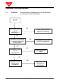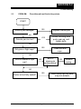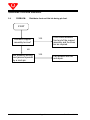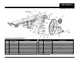
1
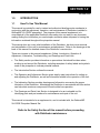
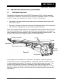
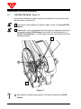
QubicaAMF
XLi EDGE Pinspotter
PIN DISTRIBUTOR MANUAL
These Original Instructions were written in English.
400-088-121 Rev. A
ALL RIGHTS RESERVED
All rights to this manual including the diagrams, figures, and technical specifications are
the property of QubicaAMF Bowling Products, Inc. Reproduction or transmission of any of
the material contained in this manual without the prior written permission of QubicaAMF
Bowling Products, Inc. is strictly prohibited. All of the product information in this manual
was carefully prepared based on the latest information available and was believed to be
correct at the time of printing. While every effort has been made to ensure accuracy, this
publication may inadvertently contain typographical errors, inaccuracies, or errors of
omission. QubicaAMF Bowling Products, Inc. cannot be held responsible for any claims
resulting from these errors.
DOCUMENT UPDATES
QubicaAMF Bowling Products, Inc. reserves the right to revise and/or update this manual
at any time without obligation to notify any person or entity of such revision. The document
number, revision level, and date below indicate the edition of this manual.
TRADEMARK NOTICES
QubicaAMF and the QubicaAMF logo are the registered trademarks of QubicaAMF
Bowling Worldwide, Inc.
QubicaAMF TECHNICAL SUPPORT
Technical Support: (International) 804.730.4000 - (Domestic) 1-866-460-7263
QubicaAMF Bowling Products, Inc.
8100 AMF Drive
Mechanicsville, Va. 23111
Copyright © 2012 QubicaAMF Bowling Products, Inc.
Document #400-088-121 Rev. A
Issue Date: 01/16/2012
QubicaAMF
XLi EDGE Pin Distributor Manual
400-088-121, Rev. A
SUMMARY OF CHANGES
Change No.
Rev. A
ECR No.
12-0053
List of Effective Pages
Page
All
Change No.
Revision A
Effective Date
1/16/2012
Table of Contents
SAFETY .....................................................................................................................................
1.0
INTRODUCTION ......................................................................................................................... 1-1
1.1
2.0
3.0
4.0
How To Use This Manual ............................................................................................. 1-1
DISTRIBUTOR OPERATION & ADJUSTMENT ........................................................................ 2-1
2.1
Distributor Operation ................................................................................................... 2-1
2.2
Distributor Belt Replacement ..................................................................................... 2-2
2.2.1 Preparing Rough Top Belts ........................................................................... 2-3
2.2.2
Vice Lacer Instructions .................................................................................. 2-4
2.2.3
Identifying a Good Splice ............................................................................... 2-5
2.3
Distributor Removal ..................................................................................................... 2-6
2.4
Distributor Replacement ............................................................................................. 2-6
2.5
Distributor Cam Operation .......................................................................................... 2-8
2.6
Distributor Adjustments .............................................................................................. 2-8
2.7
Distributor Roller Adjustment ..................................................................................... 2-9
2.8
Distributor Trip Lever .............................................................................................. 2-10
2.9
Trip Cable Adjustment .............................................................................................. 2-11
2.10
Distributor Balance Adjustment .............................................................................. 2-11
2.11
Distributor Height Adjustment................................................................................. 2-12
LUBRICATION INSTRUCTIONS ............................................................................................... 3-1
3.1
Lubrication .................................................................................................................... 3-1
3.2
Lubricant Symbols ....................................................................................................... 3-1
3.3
Distributor Drive ........................................................................................................... 3-2
3.4
Distributor ..................................................................................................................... 3-3
3.5
Distributor (continued) ................................................................................................ 3-4
PREVENTIVE MAINTENANCE................................................................................................... 4-1
4.1
25,000 Frame Maintenance .......................................................................................... 4-1
4.1.1
4.2
4.3
Servicing the Distributor Clutch Assembly................................................... 4-1
100,000 Frame Maintenance ........................................................................................ 4-3
4.2.1
Cleaning the Distributor with a Water-Based Cleaner ................................. 4-3
4.2.2
Servicing the Distributor Drive Shaft Assembly ........................................... 4-3
400,000 Frame Maintenance ........................................................................................ 4-4
4.3.1
5.0
1
Servicing the Distributor Assembly ............................................................... 4-4
TROUBLESHOOTING ................................................................................................................ 5-1
5.1
Distributor Does Not Feed Pins at Correct Bin Position .......................................... 5-1
5.2
Pins Continuously Feed Into One Bin Position ........................................................ 5-2
5.3
Pins Delivered Head First ............................................................................................ 5-3
5.4
Distributor Hits Bin During Feed ................................................................................ 5-4
Table of Contents
DRAWINGS AND PARTS LISTS ........................................................................................................... 6-1
Distributor Assembly ............................................................................................................... 6-2
Clutch and Drive Arm Assemblies ................................................................................ 6-3
Distributor Assembly 2 ............................................................................................................ 6-4
Trip Rod Assembly ......................................................................................................... 6-5
Front Carriage Assembly ................................................................................................ 6-6
Front Casting Assembly (Carriage) ............................................................................... 6-7
Rear Casting Assembly (Carriage) ................................................................................ 6-8
Main Casting and Carriage Support ........................................................................................ 6-9
Rear Belt Runner Assembly ........................................................................................... 6-10
Main Casting and Carriage Support (continued) ................................................................... 6-11
Main Casting Assembly .................................................................................................. 6-12
Front Support Assembly................................................................................................. 6-13
Drive Shaft Assemblies (Long & Short) ........................................................................ 6-14
SAFETY
Safety
SAFETY
General Safety Guidelines
QubicaAMF believes strongly in its commitment to safety. Proper service and repair
are important to the safety of the mechanic as well as the safe, reliable operation of
the pinspotters. Please read, understand, and follow all of the recommended safety
procedures presented in this manual.
The procedures recommended and described in this technical manual are effective
methods of performing service and repair. Some of these procedures require the
use of tools specially designed for this purpose.
•
Properly trained personnel should be present whenever maintenance is being
performed on a pinspotter.
•
No unauthorized personnel should be allowed in the pit area.
•
Keep in mind that the pinspotter performs a series of mechanical motions and
electrical actions during each cycle, and that bodily injury could result should
personnel enter the machine when power is on. When working on a pinspotter,
it is recommended that power also be turned off on adjacent machines.
•
Remember that safety must remain your first priority at all times.
•
Safety goggles, ear protection, and steel-toed shoes are recommended
whenever any work is being performed on a pinspotter.
•
Wearing loose clothing or jewelry is NOT RECOMMENDED when operating or
maintaining the machinery.
400-088-121
Page 1
Rev. Date 01/2012
QubicaAMF XLi EDGE Distributor
Safety Labels and Symbols
It is important to understand the safety labels and symbols used in this manual set. Three
of these labels are used to show the relative risk associated with a particular activity or
instruction. These labels are shown below in order of decreasing importance. Be aware
that taking shortcuts or failing to heed applicable safety information can result in serious
injury or damage and can render the pinspotter unsafe for you as well as for others who
follow in your place.
indicates a hazardous situation that presents a potentially crippling
or life-threatening situation.
indicates a potentially hazardous situation that could result in
serious injury or equipment damage.
indicates a potentially hazardous situation that could result in minor
to moderate injury if not avoided. It may also be used to alert
against potentially unsafe practices.
Other warning labels are conspicuously located on the pinspotter and are designed to
warn against possible hazards. These labels, some of which are shown below, are there
for your protection. Removing or disregarding these labels can result in serious injury.
400-088-121
Page 2
Rev. Date 01/2012
SAFETY
Safety
–
Refer to the Service Manual before performing
maintenance or repair.
–
Caution! Severe pinching hazard - belts.
It is also important to understand that the use of these symbols and labels is not allinclusive because it is impossible to warn of all the possible hazards and consequences
that could result from failure to follow these instructions. Trained and competent bowling
center mechanics are able to recognize and avoid potentially hazardous situations.
Guards and Safety Precautions
All safety guards must be in place before operating the machine. When maintenance
is required, the following steps must be followed:
1.
Disconnect the power plug before working on the pinspotter.
2.
Remove guards only as required to perform the maintenance.
3.
Once maintenance is complete, replace all guards.
400-088-121
Page 3
Rev. Date 01/2012
QubicaAMF XLi EDGE Distributor
This Page Intentionally Left Blank
400-088-121
Page 4
Rev. Date 01/2012
SECTION 1.0
Introduction
1.0
INTRODUCTION
1.1
How To Use This Manual
This manual is provided for use by trained and authorized bowling center mechanics in
conjunction with the adjustment, operation, and maintenance of Distributors installed in
QubicaAMF XLi EDGE pinspotters. The purpose of this manual supplement is to
consolidate all of the applicable Distributor information into one easy-to-use document
making finding the information you need simpler and faster when compared to having the
information scattered throughout the pinspotter manual.
This manual does not cover initial installation of the Distributor, but does cover removal
and reinstallation of the unit for maintenance and adjustment. Refer to the drawings at the
back of this manual for detailed views of the Distributor’s construction.
There are six parts to this manual supplement: Safety, Introduction, Operation &
Adjustment, Lubrication, Troubleshooting, and Drawings and Parts Lists.
•
The Safety section provides information on precautions that should be taken when
working in and around the Distributor, including examples of safety labels and symbols
used on the pinspotter to indicate potential hazards.
•
The Introduction Section outlines the manual.
•
The Operation and Adjustment Section gives step-by-step instructions for setting up
and adjusting the Distributor, as well as information related to the operation of the unit.
•
The lubrication Section provides drawings and information concerning the proper
lubrication of the Distributor. Maintaining the Distributor in accordance with this section
can help attain maximum component life and trouble-free operation.
•
The Drawings and Parts Lists Section is designed to be an invaluable tool for
identifying parts and part numbers for maintenance and repair of the unit.
This manual is intended to be a supplement to, and is included with, the QubicaAMF
XLi EDGE Pinspotter Manual Set.
Refer to the Safety Section of this manual before proceeding
with Distributor maintenance.
400-088-121
Page 1-1
Rev. Date 01/2012
QubicaAMF XLi EDGE Distributor
This Page Intentionally Left Blank
400-088-121
Page 1-2
Rev. Date 01/2012
SECTION 2.0
Operation & Adjustment
2.0
2.1
DISTRIBUTOR OPERATION & ADJUSTMENT
Distributor Operation
The distributor transfers pins from the EDGE Performance Lift (lift) to the bin assembly.
The distributor is driven by the back end motor through an adjustable clutch to its various
positions. A large nylon cam gear (see Figure 2-1) serves a dual purpose:
•
The outside of the gear contains a cam that moves the distributor left and right to the
various bin locations.
•
The inside of the gear has a cam that controls the telescoping action of the front portion
of the distributor. Springs keep the cam followers against the cams.
When a pin reaches the top of the pin lift, it is deposited on the pan which orients it, bottom
first, onto the distributor belt. As the pin reaches the end of the distributor, the weight of
the pin causes the trip lever assembly to pivot downward depositing the pin in the bin. The
pivot lever also causes the cam gear to index to the next bin position.
Trip Lever Assembly
Funnels
Belt
Clutch
Belt Guard
Belt Tightener Spring
Indexing
Cam/Gear
Figure 2-1
Cam Follower
Proper adjustment of all distributor components is essential for trouble-free operation.
Excessively worn parts must also be replaced. Additionally, related assemblies must be
correctly adjusted and installed. This includes the kickout springs and carrier rails. The
condition of the distributor drive shaft, universal joint, and drive housing as well as a
smooth operating pin lift are also important to trouble-free distributor operation. Also, the
flight cups, orientor pan (O-pan), and funnels should be cleaned regularly to prevent pins
from sticking.
400-088-121
Page 2-1
Rev. Date 01/2012
QubicaAMF XLi EDGE Distributor
2.2
Distributor Belt Replacement
1.
Remove the belt tightener spring (see Figure 2-1).
2.
Locate the belt lacing and remove the pin. The distributor belt can now be removed
from the distributor.
3.
To increase the belt tension, cut off a little from one end of the belt. Belt tightener
spring length will increase one-half of the amount cut off the belt. A belt that is a little
too long or short can cause pin feeding problems, and the ideal length can vary a little
from machine to machine. If replacing a worn belt that has otherwise performed well,
make the new belt the same length as the old one.
4.
If necessary, prepare a new belt in accordance with Section 2.2.1.
5.
Use the Clipper belt lacer part # 088-000-108 to install new clipper lacing on the belt in
accordance with Section 2.2.2.
6.
Thread the belt onto the distributor keeping one end on the belt runner about a foot
behind the trip arm making sure to thread the belt through the belt guard. If
necessary, use another distributor as a guide to belt layout. When threaded, bring the
two ends together, interlock the lacing, and install the belt pin.
7.
Reinstall the belt tightener spring.
8.
Turn the machine on and verify proper operation. If the belt tracks off to one side, turn
the machine off, disconnect the belt tightener spring from the distributor casting, and
move the end of the spring that is attached to the tracking bracket one notch toward
the side the belt was tracking. Reattach the other end of the spring.
9.
Run the machine and make any necessary adjustments.
The new grooved distributor belt does not require skiving when used with the QAMF lacing,
comes cut to length (116½” +1/4”,-0” [2959 mm +6 mm, -0 mm]), and is pre-chamfered. All
that is necessary is to add the lacing and install. It is always a good idea to verify the overall
length needed and to fine-tune the length by trimming as needed before applying the lacing.
The lacing will add approximately ¼ inch to the overall length.
The QubicaAMF XLi EDGE distributor uses the following belt components:
•
•
•
•
•
088-000-185, Distributor Belt, Laced
088-000-186, Stainless Steel Belt Lacing, 18 Hooks
088-000-187, Stainless Steel Belt Lacing, 19 Hooks
088-000-176, Belt Lacing Pin
088-000-108, Vise Lacer
400-088-121
Page 2-2
Rev. Date 01/2012
SECTION 2.0
Operation & Adjustment
2.2.1
Preparing Rough Top Belts
Skiving rough top and
other raised surface belting
is an important step in
achieving maximum
benefits and life from belt
splices. Clipper’s Rough
Top Belt Skiver (Fig. 2-2)
removes raised surfaces
within seconds, leaving a
smooth surface for
selecting and installing belt
fasteners. The Rough Top
Belt Skiver is a safe and
effective alternative to
other methods of removing
raised surfaces such as
grinding wheels, razor
blades or knives. Being a
hand held tool, this job can
be done virtually anywhere.
ROUGH TOP BELT SKIVER – QubicaAMF Part # 792-516-021
Figure 2-2
Instructions:
1. Place the belt on a solid
surface; hold securely with
your free hand.
Keep hand
out of the path of the skiver.
2. Hold Skiver at about a
30-degree angle to the belt
(Fig. 2-3). Slowly begin
cutting into the belt surface
just under the raised top.
4. Skive rough top back
one inch from each end to
allow clearance for lacer
jaws during lacing
operation.
To Sharpen: (Fig 2-5 A & B)
5. Place 1/4” fine stone or
emery board in cutting
channel. Draw away from
tool.
6. After tool is sharp, draw
stone across bottom to
remove burrs.
Fig. 2-5A & B
Fig. 2-4
Fig. 2-3
2.2.2
3. Maintain an even
pressure and move Skiver
across the belt (Fig. 2-4). If
held at proper angle, it will
cut through the belt easily.
CLIPPER BELT LACER INSTRUCTIONS
400-088-121
Page 2-3
Rev. Date 01/2012
QubicaAMF XLi EDGE Distributor
2.2.2
Vise Lacer Instructions
The Clipper belt lacer is provided to help the center mechanic manufacture replacement
distributor belts. The optimum belt length can vary slightly from distributor to distributor. If
possible, match the existing belt length. The belt lacing will add approximately 1/4 inch to
the overall, installed belt length. One end of the belt should have lacing containing an odd
number of individual hooks while the other end should have lacing with an even number of
hooks (see Figure 2-7b). To make a belt, proceed as follows:
1. Cut a section of belt
material to the
appropriate length
(approximately 116½ 116¾ inches). The
approximate finished
belt length is from 116¾
to 117 inches.
2. Place the open Clipper
belt lacer (Figure 2-6a)
between the jaws of a
vise. Remove the guide
pin from the hole in the
end of the lacer, if
installed.
3. Place a set of lacing
hooks in the lacer. Use
an 18-hook set on one
end of the belt and a 19hook set on the other.
Orient the lacing’s hook
retaining wire so that it
will be embedded in the
top of the belt when
crimped. Insert the guide
pin in the lacer.
4. Insert belt between hook
points. For optimal
splice, it is recommended
to have the bottom side
of belt facing the
pressure plate.
6. When complete, remove
the lacer’s guide pin,
and lift the belt out of the
lacer.
NOTE: If the belt is wider than
the vise jaws, perform the
following steps:
A. Align belt and lacer with
edge of vise jaw.
Figure 2-6b
5. Close vise as tightly as
possible, then release.
Figure 2-6d
B. Complete lacing step 5.
C. Slide tool so next section
of the lacer is in contact
with the vise jaws and
complete step 5 again.
Figure 2-6c
D. Finish with step 6.
Figure 2-6a
400-088-121
Page 2-4
Rev. Date 01/2012
SECTION 2.0
Operation & Adjustment
2.2.3
Identifying A Good Splice
Often not enough emphasis is placed on the proper selection and installation of belt
laces. Unfortunately, if improperly installed, the result can be detrimental — shortened
splice life, added costs, and increased down-time; just to mention a few. Listed below
are suggestions, which if followed, will increase your splice longevity.
What to look for:
1. Skive rough top back approximately one inch. Use
proper size lacing based on skived belt thickness and
pulley diameter. The correct lacing is provided with
the distributor belt assembly.
2. Hook is properly sized and clinched when: (Fig. 2-7a)
A. Hook legs are parallel. Loop should not have a
light bulb shape.
Figure 2-7a
B. Hook points slightly penetrate opposite side of belt
(.005 to .015 inches).
C. 1/3 - 1/2 of the wire diameter is embedded into the
belt.
D. The “Knuckles” of the hook should not be higher
than the legs when installed.
3. Leave 1/4 inch on each edge of belt unlaced. This
guards against end hooks being pulled out.
4. Use one more hook on leading edge than on trailing
edge (Fig. 2-7b).
Figure 2-7b
5. Chamfer the trailing edge. (QubicaAMF’s new
grooved belts are already chamfered.)
6. Laces should be uniformly embedded across the
entire width of the splice.
7. Edges of the belt should line up when the laced belt
ends are connected.
8. Run fingernail across loops of splice. Loops should
not move.
400-088-121
Page 2-5
Rev. Date 01/2012
QubicaAMF XLi EDGE Distributor
2.3
Distributor Removal
1.
Disconnect the drive shaft from the distributor at the universal joint, and remove the
drive shaft assembly.
2.
Remove the lateral drive spring first and then the safety link spring from the base of
the distributor (see Figure 2-8).
3.
Remove the orientor pan and support bracket from the pin lift.
4.
Lift the distributor assembly upward off the support post. Save the spacer between
the support post and the distributor (if present) for reuse during distributor
installation.
Lateral Drive Spring
Safety Link Spring
DISTRIBUTOR 4
Figure 2-8
2.4
Distributor Replacement
1.
To replace the distributor assembly, follow the removal procedure in reverse order.
Ensure that only one spacer is installed between the support post and the
distributor.
2.
Check the pinion and cam gear timing marks for correct alignment. The distributor
must be at the #1 bin position when checking or adjusting. There is a raised bump
on the large cam gear at the base of one of the valleys between the teeth, and a
notched tooth on the pinion gear that must be opposite one another for correct
timing. To realign, remove the clutch and pinion and reposition the cam gear so
that the timing marks align when the pinion is reinstalled, then reinstall the clutch.
400-088-121
Page 2-6
Rev. Date 01/2012
SECTION 2.0
Operation & Adjustment
Clutch Spring
Trip Stop
Rod Assembly
Nut
Return Spring
Figure 2-9
3.
Set the clutch spring tension (Figure 2-9). With the clutch nut finger tight on the
shaft, rotate the spring’s adjusting clip in the counterclockwise direction until you
just start to feel some spring tension. Continue rotating the clip an additional 3/4
turn, and then slide the clip onto the clutch nut. Power up the machine and feed
pins.
a. If the spring is not tensioned enough, the distributor will stall between the #6
and #10 positions. Add more tension to correct this condition, but not more
than a total of one turn.
b. If the distributor hesitates or fails to index, other than mentioned in the previous
step, tension must be removed by reducing the spring tension.
c. Adjust the spring tension one notch at a time, and use the minimum tension that
produces acceptable results.
4.
The distributor should not touch any part of the pin elevator (lift) or Durabin during
operation. If adjustment is necessary, add or remove spacer washers from the
distributor mounting bolts.
400-088-121
Page 2-7
Rev. Date 01/2012
QubicaAMF XLi EDGE Distributor
2.5
Distributor Cam Operation
The indexing cam has a timing mark along its outer edge at the base of a valley between
two teeth. This bump and a notched tooth on the pinion gear must be aligned for proper
timing. (See section 2.4 for instructions on how to realign the cam and pinion gears.) A
cam follower on the drive arm assembly traces a path along the cam on the outer face of
the large indexing cam when the indexing cam is rotating. This action causes the
distributor to pivot left and right as required to align the distributor with the bin pockets.
The inside cam of the indexing cam controls the telescoping of the distributor using cam
sections and cam followers on the carriage drive arm assembly in a manner similar to the
operation described in the previous paragraph. During operation, the distributor is forced
inward by the action of the inner cam followers, and telescopes outward because of a
combination of return spring tension and a moving belt’s tendency to straighten out
whenever the cam follower’s linkage allows it to do so. The combination of the two actions
described above results in a pin feed sequence of 1, 3, 2, 4, 7, 8, 5, 6, 10, 9.
2.6
Distributor Adjustments
1.
Index the trip stop rod (Figure 2-9) to position the distributor at the #1 bin position.
2.
Inspect the nylon cam gear and pinion gear to verify that the timing marks are aligned.
3.
The distributor should be in line with the #1 and #5 bin positions. To adjust, loosen
the jam nut on the rectangular support post end of the safety link rod (see Figure 210) and rotate the safety link rod to either increase or decrease the length of the rod
to obtain the correct alignment. Tighten the jam nut.
4.
Operate the machine and note the pin feed operation at the individual bin pockets.
The rod length may have to be readjusted slightly to obtain accurate pin feed.
Safety Link Rod
Jam Nut
DISTRIBUTOR 4
Figure 2-10
400-088-121
Page 2-8
Rev. Date 01/2012
SECTION 2.0
Operation & Adjustment
2.7
Distributor Eccentric Roller Adjustments
1.
Starting with the distributor at the #1 bin position and the back end drive motor
turned off, telescope the distributor inward so that it is at its minimum length.
2.
Position the lower front adjustable roller in its lowest position so that the distance
between the roller and the carriage tube is at its maximum. (See Figure 2-11.)
Upper Front
Adjustable Roller
Rear Adjustable Roller
Carriage Tube
Trip Rod
Tube
Lower Front
Adjustable Roller
Nylon Roller
Clearance 1/16-inch
Non Adjustable
Rear Roller
DISTRIBUTOR
DISTR
IBUTOR ROLLERS
ROLLERS
Figure 2-11
3.
Bring the rear adjustable roller down until there is a noticeable drag against the
carriage tube when you turn the roller. (Too much drag could prevent the distributor
from extending.)
4.
Adjust the upper front adjustable roller until the trip rod tube and carriage tubes are
parallel to each other.
5.
Position the lower front adjustable roller up until it just makes contact with the
carriage tube.
6.
Recheck the rear adjustable roller to ensure that it is not exerting too much
pressure against the carriage tube. Adjust if necessary.
7.
Adjust the length of the cable assembly (Figure 2-12) so that the clearance between
the nylon rollers and the trip rod tube is approximately 1/16 inch (Figure 2-11) and
is the same in all positions of the distributor.
8.
Operate the distributor under power and observe. As necessary, fine-tune the
rollers and trip cable.
400-088-121
Page 2-9
Rev. Date 01/2012
QubicaAMF XLi EDGE Distributor
Cable Assembly
Figure 2-12
2.8
Trip Rod Tube
DISTRIBUTOR
DISTRIBUTOR
33
Distributor Trip Lever
1.
Operate the distributor trip lever. Inspect for mechanical binds in the lever and
associated linkage. Check that the rollers turn freely.
2.
As a pin transfers from the distributor belt onto the trip lever, the weight of the pin
causes the lever to pivot downward as the pin is deposited in the bin. Afterwards,
the trip lever returns to the up position from the force of a spring located at the rear
of the carriage tube (see Figure 2-13). This tripping and resetting action actuates
the trip rod allowing the distributor to index to the next bin position. The spring
tension is factory set for 1/2 turn. Too little spring tension (worn or damaged spring)
would cause the trip lever to deflect too soon causing the distributor to index before
the pin has cleared the trip lever resulting in misfed pins.
Trip Lever
Spring
Figure 2-13
400-088-121
Page 2-10
Rev. Date 01/2012
SECTION 2.0
Operation & Adjustment
2.9
Trip Cable Adjustment
One end of the trip cable attaches to the trip lever on the end of the carriage, and the
other end connects to the trip rocker arm weldment (the D-shape metal piece). Two
nylon rollers on the inside of the trip rocker arm weldment straddle the trip rod, and
when adjusted properly, should not touch the trip rod. This arrangement allows the
distributor carriage to telescope in and out freely without actuating the trip rod. When a
pin causes the trip lever to pivot, the cable transmits this action to the rocker arm
weldment causing the nylon rollers to pivot actuating the trip rod, which in turn causes
the indexing cam to move the distributor to the next bin position.
The spacing between the rollers and the trip rod should be approximately equal, and if
the carriage adjustment is correct (see Section 2.7, Distributor Eccentric Roller
Adjustment) the rollers should not contact the trip rod when the carriage is moved in and
out along its range of travel.
To adjust the cable:
1.
Loosen the jam nut on the end of the trip cable that is being adjusted.
2.
Remove the cable connector from the ball stud.
3.
To increase the gap between the lower roller and the trip rod, lengthen the cable
(unscrew the connector). To decrease the gap, shorten the cable.
4.
Reattach the cable to the ball stud.
5.
Tighten the jam nut.
2.10
Distributor Balance Adjustment
Distributor balance is checked by removing the drive shaft between the distributor and
back end motor as well as the lateral and safety link springs, and positioning the
distributor in line with, and extended to, the headpin bin pocket. The Distributor should
remain at the head pin location, fully extended and should not fall to either the 7-pin or
10-pin side of the Durabin. If it does, the distributor mount must be adjusted until the
distributor stays at the head pin location.
To Adjust:
Note: Ensure that at least one side of the rear distributor mount is always in contact (or
as low as possible in the slot) with the rear distributor support bracket.
1.
Loosen the nut and bolt on the rear distributor mount on the side to which the
distributor falls.
400-088-121
Page 2-11
Rev. Date 01/2012
QubicaAMF XLi EDGE Distributor
2.
While holding the distributor centered over the head pin, tap the upright section of
the distributor mount until the distributor stays centered over the head pin pocket of
the bin by itself.
3.
Tighten the nut and bolt holding the rear distributor mount to the support bracket.
2.11
Distributor Height Adjustment
1.
With the distributor fully retracted, the distributor’s belt guard should be ¼ to ½ inch
above the ridge that runs along the back of the Durabin. To adjust distributor
height, add or remove washers from under the front distributor mount between the
mount and the front support bracket.
2.
If an adjustment is made, check the distributor balance as specified in the previous
section.
400-088-121
Page 2-12
Rev. Date 01/2012
SECTION 3.0
Lubrication
3.0
LUBRICATION INSTRUCTIONS
3.1
LUBRICATION
Lubrication is one of the most important items in the proper operation and maintenance
of the distributor. Care must be taken to ensure that lubricants are applied correctly.
Avoid excessive lubrication to minimize the possibility of transmitting lubricants to the
bowler. Before lubricating exposed parts or surfaces, it is important that the old
lubricant first be removed. It is also very important to clean the distributor as you
lubricate.
This section is intended to show the points of lubrication, specify the correct quantity
and type of lubricants to use, and indicate the frequency of lubrication for each part of
the distributor that requires lubrication. Refer to Section 4.0, Preventive Maintenance,
for specific instructions relating to distributor lubrication.
3.2
LUBRICANT SYMBOLS
OILING: Items indicated by a number within a square 1
oil as the lubricant.
GREASING: Items indicated by a number within a circle 1
multi-purpose grease (Bearing Guard #2) as the lubricant.
400-088-121
Page 3-1
require oiling. Use SAE #10
require greasing. Use a
Rev. Date 01/2012
QubicaAMF XLi EDGE Distributor
3.3
DISTRIBUTOR DRIVE - Figure 3-1
Lubricate the distributor as part of preventive maintenance in accordance with
the instructions in Section 4.0.
1 Trip support casting bearings (2 places): apply 2 drops of oil every 25,000
frames.
2 Disassemble, clean, and lubricate the pinion gear in conjunction with clutch
maintenance every 25,000 frames (see section 3.4 and subsection 4.1).
Do NOT overlubricate or oil could migrate into the clutch preventing it from
operating properly.
1
1
2
Figure 3-1
1 Stop blades (2 places): apply grease to the back surfaces every 25,000
frames.
400-088-121
Page 3-2
Rev. Date 01/2012
SECTION 3.0
Lubrication
3.4
DISTRIBUTOR - Figure 3-2
1
Trip lever rollers (8 places): apply 1 drop of oil every 50,000 frames.
2
Trip lever bushings (2 places): apply 1 drop of oil every 25,000 frames.
3
Distributor clutch assembly (1 place): disassemble, clean, lubricate the
thrust washer, and adjust every 25,000 frames (see subsection 4.1).
3
1
2
Figure 3-2
1
Clutch Assembly
1 Distributor support bearings (2 places): remove distributor and grease
bearings every 100,000 frames.
400-088-121
Page 3-3
Rev. Date 01/2012
QubicaAMF XLi EDGE Distributor
3.5
DISTRIBUTOR - Figure 3-3
1. Trip rod (front) (1 place): 1 drop of oil every 25,000 frames.
2. Trip rocker arm (2 places): apply 1 drop of oil to each side every 25,000 frames.
3. Roller tracking bracket (4 places): 1 drop of oil every 25,000 frames.
2
1
3
Figure 3-3
400-088-121
Page 3-4
Rev. Date 01/2012
SECTION 4.0
Preventive Maintenance
4.0
PREVENTIVE MAINTENANCE
This section provides specific preventive maintenance instructions for servicing
pinspotters on a frequency based on frame count. Repeat each maintenance item at
every multiple of the indicated frame count. For example, a maintenance activity
performed at 25,000 frames would be repeated at 50,000, 75,000, 100,000, 125,000,
etc. A 100,000 frame maintenance activity is repeated at 200,000, 300,000, etc.
Maintenance may need to be done more frequently based on the distributor’s age,
mechanical condition, and repair history.
4.1
4.1.1
25,000 Frame Maintenance
Servicing the Distributor Clutch Assembly
1. Index the Distributor to the #1 pin location.
2. Remove power from the pinspotter. Follow appropriate Lock out/Tag out
procedures.
3. On the odd pinspotter, remove the Hitch Pin. On the even pinspotter, remove the
Hitch Pin if it is still there (it is not needed – save as a spare).
4. On the odd pinspotter, remove the Distributor Drive Shaft Assembly. Inspect the
Drive Shaft for missing or excessively worn parts. Replace parts as needed, and
set aside.
5. Carefully remove the Clutch Tension Spring by carefully pulling the center piece off
the large nut, and then allowing the spring to unwind slowly. Remove the end of the
spring from the black Clutch Plate.
6. Turn the spring around and use the center as a wrench to loosen the large nut. Turn
the nut counter-clockwise to loosen while applying pressure to the Distributor Belt at
the pulley with your other hand.
7. Remove the nut and the special washer from the Distributor Shaft.
8. Grasp the gold Clutch Plate and remove the Clutch Assembly as a unit. The Pinion
Gear, Sleeve, and Thrust Washer may come off with the gold Clutch Plate
Assembly, but if they don’t, remove them. Be careful not to drop them.
9. Clean and dry all parts that were removed. Use a water-based cleaner such as
diluted ACC, window cleaner, or Simple Green™.
10. Remove the old grease from the Stop Blade on the Trip Rod assembly.
11. Examine all parts for excessive wear. Replace as required. Make sure the Pinion
Gear Sleeve is longer than the Pinion Gear.
12. Spread a light film of SAE #10 oil on the side of the Thrust Washer that will be in
contact with the Pinion Gear. Install the Thrust Washer on the Distributor Shaft.
400-088-121
Page 4-1
Rev. Date 01/2012
QubicaAMF XLi EDGE Distributor
13. Spread a light film of SAE # 10 oil on the Pinion Gear Sleeve. Install the sleeve on
the Distributor Shaft.
14. Install the Pinion Gear on the sleeve aligning the cut tooth with the raised bump on
the Indexing Cam.
15. Apply grease to the back side of the Stop Blades on the Trip Rod Assembly and to
the front side of the Stop Blade on the gold Clutch Plate Assembly.
16. Install the gold Clutch Plate Assembly engaging it onto the Pinion Gear (they are
keyed to each other). To make installing the Clutch Plate easier, hold the plate
assembly in your right hand making sure its stop blade is behind the stop blades on
the Trip Rod Assembly. While applying gentle pressure to the gold Clutch Plate
Assembly against the Pinion Gear, rotate the Index Cam counterclockwise with your
left hand until the gold Clutch Plate Assembly locks onto the Pinion Gear.
17. Install the special washer against gold Clutch Plate.
18. Install the Worm onto the Distributor Shaft against the special washer. The word
“out” is printed on the Worm and must be facing away from the gold Clutch Plate
Assembly when the Worm is installed.
19. Install the Friction Disc and black Clutch Plate, screwing the Clutch Plate
counterclockwise onto the Worm. Leave the Clutch Plate loose until after installing
the large nut. Turning the Clutch Plate too much will cause the Worm to pull away
from the special washer and will result in damaging the Clutch Plate when the large
nut is tightened.
20. Install the other special washer and the large nut. Tighten the nut by turning it
clockwise using the center part of the Clutch Tension Spring as your wrench. You
will have to hold the Distributor Belt Pulley while tightening the nut.
21. Install the straight piece of the Clutch Tension Spring into the 2 holes on the Clutch
Plate. The straight piece goes into one of the holes and must come out of the other
hole.
22. Rotate the Clutch Plate counterclockwise until the plate is tight making sure that the
Friction Disc is contained within the gold Clutch Plate Assembly edges.
23. Grasp the center part of the Clutch Tension Spring and rotate it counterclockwise
3/4 to 1 turn, and then place the spring’s center clip onto the large nut. You may
need to hold the Distributor Belt Pulley so that the shaft does not turn when
tensioning the spring.
24. On odd pinspotters, install the Distributor Drive Shaft Assembly. Attach it to the
Distributor using the Hitch Pin. A hitch pin is not used on even pinspotters.
25. Apply power to the pinspotter and cycle it. Observe for correct Distributor operation.
400-088-121
Page 4-2
Rev. Date 01/2012
SECTION 4.0
Preventive Maintenance
4.2
100,000 Frame Maintenance
4.2.1
Cleaning the Distributor Assembly with a Water-Based Cleaner
1.
Index the Distributor to the headpin position.
2.
Remove power from the pinspotter. Follow the appropriate Lock out/Tag out
procedures.
3.
Wipe all surfaces of the Distributor Assembly with a cloth dampened with a waterbased cleaner.
4.
Clean (scrape, if needed) all Distributor belt pulleys (rollers), removing any black
buildup.
5.
Check for worn, broken, or loose parts or hardware. Tighten or replace as needed.
6.
Lubricate the Distributor following the instructions and drawings in Section 3.
7.
Wipe the O-Pan and Funnels with a vinyl dressing.
8.
Apply power and cycle the pinspotter. Observe for correct distributor operation.
4.2.2
Servicing the Distributor Drive Shaft Assembly
1.
Run the Sweep to the 1st Guard position.
2.
Remove power from the pinspotter. Follow the appropriate Lock out/Tag out
procedures.
3.
Remove the Distributor Drive Shaft Assembly from the Distributor and Gearbox
Drive Housing.
4.
Wipe all the grease from the end of the Distributor Drive Shaft that was within the
Drive Housing.
5.
Check the balls for wear and flat spots. Replace as needed.
6.
Check that the correct washers and spacer are in place. Replace as needed.
7.
Check that the ball bearing retainer is not bent or broken. Replace as needed.
8.
Check that the dowel pin cannot be pushed out by finger pressure. Replace as
needed. If the new dowel pin can be pushed out, the shaft needs to be replaced.
9.
Check the universal joint for excessive play. Replace as needed.
10. Wipe all the grease from the Drive Housing.
11. Check that the Drive Housing is tight on the gearbox shaft. Tighten as needed.
12. Check for wear and grooving on the Drive Housing where the balls of the Distributor
Drive Shaft ride. Replace as needed.
13. Apply a liberal amount of grease to the inside of the Drive Housing and to the balls,
spacers, and washers of the Distributor Drive Shaft Assembly.
400-088-121
Page 4-3
Rev. Date 01/2012
QubicaAMF XLi EDGE Distributor
14. Install the Distributor Drive Shaft on the Gearbox and Distributor. Install the Hitch
Pin on the odd pinspotter.
15. On the odd pinspotter, with the Distributor at the headpin location, check that the
drive shaft does not bottom out in the Back End Motor Drive Housing. If it does, and
there is room for adjustment of the housing on the shaft, then adjust the housing;
otherwise, the Tie Plate and PBL Spring Bracket nuts and bolts need to be
loosened and the Motor and Gearbox Assembly moved away from the Distributor,
and the nuts and bolts retightened.
16. On the odd and even pinspotters, index the Distributor to the 7-pin and 10-pin
locations. Check that the Drive Shaft balls don't extend past halfway off the open
end of the Drive Housing while in the 7-pin and then the 10-pin position. Loosen the
set screw in the Drive Housing and reposition if necessary. If an adjustment was
made, recheck per step 15.
17. Run the Sweep to the Home position.
18. Apply power and cycle the pinspotter. Observe for correct Distributor operation.
4.3
400,000 Frame Maintenance
4.3.1
Servicing the Distributor Assembly
1.
For ease of disassembly, a fixture should be built to hold the Distributor while it is
being worked on.
2.
Run the Sweep to the 1st Guard position.
3.
Remove power from the pinspotter. Follow the appropriate Lock out/Tag out
procedures.
4.
Remove the O-Pan from the Edge Performance Lift.
5.
Remove the Distributor from the pinspotter.
6.
Clean all components and parts with a cloth dampened with a water-based cleaner.
7.
Use light weight oil on all bushings and sleeve items when assembling.
8.
Remove the Distributor Belt.
9.
Remove the Carriage Assembly by removing the Belt Runner, Eccentric Rollers,
and the Connecting Link.
10. Remove both pulleys from the Carriage Assembly by removing the Trip Arms, shaft,
and tubes (both ends).
11. Check for binding or noisy bearings in the pulleys. Replace as needed.
12. Check the pulleys for grooving, loss of crown, bearings fitting too loosely and
replace as needed. Clean off all dirt if reusing the pulleys.
400-088-121
Page 4-4
Rev. Date 01/2012
SECTION 4.0
Preventive Maintenance
13. Check for excessive wear on the shafts and bushings in the tubes. Replace as
needed.
14. Check for cracked, broken, or worn eccentric and concentric rollers. Replace as
needed.
15. Check for loose or missing hardware on the Belt Runner Support. Replace as
needed.
16. Check for bent Carriage Tubes and Pin Guides. Replace as needed.
17. Remove the Tracking Bracket, Tube Assembly, and pulley.
18. Check the Tracking Bracket and Roller Assembly Links for cracks or bends.
Replace as needed.
19. Check for binding or noisy bearings in the pulley. Replace as needed.
20. Check the pulleys for grooving, loss of crown, bearings fitting too loosely, and
replace as needed. Clean off all dirt if reusing pulleys.
21. Check spacers and Tube Assembly bushings for excessive wear. Replace as
needed.
22. Check the Distributor Cable for fraying and the ball joints for excessive wear.
Replace as needed.
23. Check the Belt Guard for wear or damage. Replace as needed.
24. Check the rollers on the Trip Rocker Arm Weldment for wear (flat spots) and that
they roll freely. Replace or lubricate as needed.
25. Reassemble the Carriage Assembly.
26. Remove the Distributor Clutch Assembly.
27. Remove the Drive Arm Assembly.
28. Remove the Index Cam. Check the bearings on the Index Cam shaft for noise or
binding. Replace as needed.
29. Check for noisy or binding bearings in the Drive Arm Assembly. Replace as
needed.
30. Check all three Cam Followers for excessive wear and that they roll freely. Replace
as needed.
31. Check the Index Cam for cracks or missing teeth. Replace as needed.
32. Check the arm for cracks around the Link Attachment countersunk hole, and that
the arm pivots freely. Replace the arm and/or bearings in the main casting as
needed.
33. Remove the Trip Rod Assembly.
34. Check for excessive wear or bends on Trip Rod Assembly. Replace as needed.
35. Check the Stop Blade for excessive wear. Replace as needed.
36. Check for a worn or missing bumper on the Trip Stop Support Bracket.
400-088-121
Page 4-5
Rev. Date 01/2012
QubicaAMF XLi EDGE Distributor
37. Check the straightness of the Drive Shaft. Replace as needed.
38. Check the bearings on the Drive Shaft for noise or binding. Replace as needed.
39. Reassemble the Distributor.
40. Service the Distributor Clutch.
41. Install the Distributor.
42. Install the O-Pan and supports.
43. Return power to pinspotter.
44. Run the Sweep to the Home position.
45. Cycle the pinspotter and observe for correct Distributor operation.
400-088-121
Page 4-6
Rev. Date 01/2012
SECTION 5.0
Troubleshooting
5.0
TROUBLESHOOTING
5.1
PROBLEM:
Distributor does not feed pins at correct bin position.
START
Distributor drive cam
indexed with pinion
gear?
NO
Check bump on indexing gear
with notched tooth on pinion
gear. Align if necessary. Make
sure Distributor is in the #1 bin
position when aligning.
YES
NO
Distributor centered
properly?
400-088-121
Page 5-1
Run distributor to #1 bin
position and center by
adjusting the safety link.
Rev. Date 01/2012
QubicaAMF XLi EDGE Distributor
5.2
PROBLEM:
Pins feed into bin continuously at one bin position or
too many pins in one bin location.
START
Distributor clutch
out of
adjustment?
YES
Check spring tension.
Adjust if necessary.
NO
YES
Distributor clutch dirty
or contaminated with
oil or grease?
Disassemble and clean
clutch components
NO
Distributor rollers
out of
adjustment?
YES
Adjust distributor
rollers.
NO
Distributor stop
blades need
lubrication.
400-088-121
YES
Apply light coat
of grease to
stop blades.
Page 5-2
Rev. Date 01/2012
SECTION 5.0
Troubleshooting
5.3
PROBLEM:
Pins delivered head first to bin pockets.
START
Orientor pan damaged?
YES
Replace orientor pan.
NO
Loosen mounting bolts,
push o-pan up, and
tighten bolts.
YES
Orientor pan too low?
NO
Dirty pins or flight cups?
YES
Clean pins and
cups.
NO
Pins not seated in flight
cup?
YES
Bent or
missing pin
seating spring?
YES
Replace
spring.
NO
NO
Carrier rail not fully seated?
400-088-121
YES
Page 5-3
Insert carrier rail until nubs
snap into detents.
Rev. Date 01/2012
QubicaAMF XLi EDGE Distributor
5.4
PROBLEM:
Distributor front end hits bin during pin feed.
START
Distributor support
assembly too low?
YES
Place shims between
front end of the support
assembly and the cross
bar as required.
NO
Bin assembly binding
and jammed upwards
by a stuck pin.
400-088-121
YES
Page 5-4
Find problem with bin
and repair.
Rev. Date 01/2012
SECTION 6.0
Drawings and Parts Lists
Drawings
and
Parts Lists
400-088-121
Page 6-1
Rev. Date 01/2012
SECTION 6.0
Drawings and Parts Lists
Distributor Assembly, 088-005-100
Item
Part Number
1
2
3
4
5
6
7
8
9
088-005114
090-006-266
070-006-048
070-006-839
070-006-065
948-975-172
844-073-002
722-501-088
088-005-117
Description
Distributor Index Cam
Distributor Clutch Assembly
Special Bolt
Distributor Drive Arm Assembly
Race Clamp
Flat Washer, .53 x 1.06 x .10
Nut, ½-13 Stover Lock
Spacer, .51 x .75 x .42
Carriage Drive Cam Arm Assembly
Item
Part Number
10
11
12
13
14
15
16
17
18
070-006-034
000-026-031
088-000-185
088-000-186
088-000-187
088-000-176
000-022-173
808-849-100
088-000-184
Description
Linear Spring
Belt Tensioner Spring
Distributor Belt, Laced
UX-1 Belt Lacing – 18 Hooks
UX-1 Belt Lacing – 19 Hooks
Distributor Belt Pin
Special Nut, Roller Drive Assembly
Screw, ¼-20 x 5/8, Hex Socket Flat Head
Hitch Pin
Bold items indicate that a detailed drawing for that assembly is shown on the following pages.
400-088-121
Page 6-2
Rev. Date 01/2012
QubicaAMF XLi EDGE Distributor
070-006-839
090-006-266
Clutch & Drive Arm Assemblies
088-005-117
400-088-121
Page 6-3
Item
Part Number
1
2
3
4
5
6
7
8
9
10
11
12
13
14
15
16
17
18
19
20
21
22
23
088-000-192
070-006-686
070-006-676
088-005-119
070-006-126
070-006-130
070-006-125
070-006-121
070-006-128
835-582-002
070-006-052
070-006-071
844-050-002
000-024-679
919-000-600
090-005-262
070-006-069
070-006-064
088-005-115
808-849-160
088-005-118
070-006-111
000-022-173
Description
Clutch Assembly
Pinion Gear Assembly
Distributor Drive Sleeve
Thrust Washer
Friction Disc
Clutch Plate
Adjusting Worm
Clutch Washer
Spring Assembly
Nut, Hex Jam, 5/8 x 18
Drive Arm
Cam Follower
Nut, ¼-28, Stover Lock
Ball Bearing, .625 x 1.375
Retaining Ring
Rod Link Assembly
Nut, Special
Bearing Spacer
Distributor Cam Tele-Arm
Screw, Hex Socket Flat Head, ¼-20 x 1
Spacer, Cam Spring Post
Spring Post Sleeve
Nut, Special, Roller Drive Assembly
Rev. Date 01/2012
SECTION 6.0
Drawings and Parts Lists
Distributor Assembly 2, 088-005-100
Item
Part Number
1
2
3
4
5
6
7
8
9
070-006-837
809-849-125
844-049-002
070-006-118
070-006-845
809-849-165
090-006-668
000-026-865
070-006-685
400-088-121
Description
Front Carriage Assembly
Screw, Hex, ¼-20 x ¾
Nut, ¼-20, Stover Lock
Bearing, Grooved, Eccentric
Trip Cable Assembly
Screw, Hex, ¼-20 x 1
Trip Rod Assembly
Washer, ¼ I.D. x 7/8 O.D.
Pivot
Page 6-4
Rev. Date 01/2012
QubicaAMF XLi EDGE Distributor
Trip Rod Assembly, 090-006-668
Item
Part Number
1
2
3
4
5
6
7
090-006-663
090-006-665
809-849-125
070-006-691
844-049-002
701-712-097
809-849-165
400-088-121
Description
Trip Stop Rod Assembly
Trip Support Casting
Screw, Hex, ¼-20 x ¾
Trip Arm Stop Blade
Nut, ¼-20, Stover Lock
Bearing, Spyralign, Bronze, .375
Screw, Hex, ¼-20 x 1
Page 6-5
Rev. Date 01/2012
SECTION 6.0
Drawings and Parts Lists
Front Carriage Assembly, 070-006-837
Item
Part Number
Description
1
2
3
4
5
6
7
8
9
10
070-006-832
070-006-013
810-239-160
070-006-009
070-006-004
913-437-140
070-006-833
806-249-060
070-006-137
840-039-002
Front Casting Assembly, Carriage
Pin Guide
Screw, Hex Socket Head, #10-24 x 1
Belt Runner Support Assembly
Tube, Carriage Assembly
Spring Pin, .187 x .875
Rear Carriage Casting Assembly
Set Screw, Square Head, Round Point, ¼-20 x 3/8
Belt Guard
Nut, #10-24, Flexloc, Thin
400-088-121
Page 6-6
Rev. Date 01/2012
QubicaAMF XLi EDGE Distributor
Front Casting Assembly, Carriage: 070-006-832
400-088-121
Page 6-7
Item
Part Number
1
2
3
4
5
6
7
8
9
10
11
12
070-006-055
070-006-021
070-006-011
070-006-142
907-000-100
070-006-014
070-006-116
843-149-002
070-006-016
070-006-015
090-004-111
840-040-002
Description
Carriage Casting, Front
Tube Assembly, Carriage, Front
Pulley Assembly
Bumper
Key
Trip Arm Pivot Shaft
Clamp Stud
Nut, ¼-20, Keps
Trip Arm Assembly, Left
Trip Arm Assembly, Right
Ball Stud, #10-32 x .56
Nut, #10-32, Flexloc
Rev. Date 01/2012
SECTION 6.0
Drawings and Parts Lists
Rear Casting Assembly, Carriage: 070-006-833
400-088-121
Page 6-8
Item
Part Number
1
1A
1B
1C
1D
1E
1F
2
3
4
5
6
7
8
9
10
11
12
070-006-836
070-006-672
070-006-011
070-006-683
070-006-116
843-149-002
070-006-142
070-006-659
070-006-661
070-001-857
919-005-000
070-006-835
070-006-029
090-004-110
840-040-002
070-006-019
070-006-035
919-006-800
Description
Rear Casting Assembly, Partial
Carriage Casting, Rear
Pulley Assembly
Tube Assembly, Rear Casting
Clamp Stud
Nut, ¼-20, Keps
Bumper
Trip Rocker Shaft
Trip Rocker Arm Weldment
Roller, Actuator Assembly
Retaining Ring
Special Nut & Set Screw Assembly
Connecting Link
Ball Stud, #10-32 x .44
Nut, #10-32, Flexloc
Spring Collar
Trip Arm Torsion Spring
Retaining Ring
Rev. Date 01/2012
QubicaAMF XLi EDGE Distributor
Main Casting and Carriage Support
Item
Part Number
1
2
3
4
5
6
7
8
9
10
11
088-001-511
088-001-512
070-006-846
808-549-200
948-753-102
843-149-002
070-006-084
070-006-142
844-049-002
088-001-548
809-849-205
400-088-121
Description
Distributor Funnel, 10-Pin Side
Distributor Funnel, 7-Pin Side
Rear Belt Runner Assembly
Screw, Button Head, ¼-20 x 1¼
Washer, Flat, ¼
Nut, Keps, ¼-20,
Trip Stop Support Bracket
Bumper
Nut, Stover Lock, ¼-20,
Trip Arm Spacer
Screw, Hex, ¼-20 x 1¼,
Page 6-9
Rev. Date 01/2012
SECTION 6.0
Drawings and Parts Lists
Rear Belt Runner Assembly, 070-006-846
Item
Part Number
1
2
3
4
5
6
7
8
070-006-103
070-006-104
070-006-042
088-001-578
070-006-139
809-849-885
844-049-002
000-026-865
400-088-121
Description
Support Guide, L.H.
Support Guide, R.H.
Belt Runner
Outer Spacer
Inner Spacer
Screw, Hex, ¼-20 x 5½
Nut, ¼-20, Stover Lock
Washer, ¼ x 7/8
Page 6-10
Rev. Date 01/2012
QubicaAMF XLi EDGE Distributor
Main Casting & Carriage Support 2
Item
Part Number
Description
1
2
3
4
5
6
7
8
9
10
11
12
13
400-088-121
070-007-138
070-006-841
070-006-061
070-006-049
070-006-666
070-006-120
070-006-838
913-464-280
810-239-240
840-039-002
948-745-082
809-857-080
948-761-112
Main Casting Assembly
Main Shaft Assembly
Cam Shaft
Arm Shaft
Belt Drive Pulley
Carriage Support Tube
Front Support Assembly
Roll Pin, Steel, 3/8 x 1¾
Screw, Socket Head, #10-24 x 1½
Nut, Flexloc, #10-24, Thin
Washer, Plain, #12 x 1/16 Thick
Screw, Hex, 5/16-18 x ½
Washer, Flat, 5/16
Page 6-11
Rev. Date 01/2012
SECTION 6.0
Drawings and Parts Lists
Main Casting Assembly, 070-007-138
Main Shaft Assembly, 070-006-841
Item
Part Number
1
2
3
4
5
6
7
8
9
10
11
12
13
14
15
070-006-053
070-006-076
070-006-075
070-006-074
070-006-073
070-006-064
000-024-679
919-004-200
919-000-600
919-005-300
070-006-082
000-026-081
070-006-077
913-437-140
919-005-600
400-088-121
Description
Distributor Base Casting
Bearing, Open End
Bearing, Closed End
Thrust Bearing
Thrust Washer
Bearing Spacer
Ball Bearing, .625 x 1.917
Retaining Ring, Large
Retaining Ring, Med.
Retaining Ring, Small
Spring Pin
Spring Post Sleeve
Distributor Drive Shaft
Spring Pin, .187 x .875
Retaining Ring
Page 6-12
Rev. Date 01/2012
QubicaAMF XLi EDGE Distributor
Front Support Assembly, 070-006-838
Item
Part Number
1
2
3
4
5
6
7
8
9
10
11
12
13
14
15
16
17
070-006-688
701-710-098
070-006-117
070-006-118
701-849-124
809-849-165
070-006-105
070-006-108
809-849-605
070-006-111
844-049-002
070-006-160
070-006-116
843-149-002
070-006-011
070-006-106
070-006-109
400-088-121
Description
Carriage Support Casting, includes item 2
Spyralign Bearing, .313 Bore
Bearing, Grooved, Concentric
Bear Grooved, Eccentric
Bearing, Threaded Bore
Screw, Hex, ¼-20 x 1
Tube Assembly
Spacer, Roller Assembly
Screw, Hex, ¼-20 x 3-3/4
Spring Post Sleeve
Nut, ¼-20, Stover Lock
Belt Tightener Assembly
Clamp Stud
Nut, ¼-20, Keps
Pulley Assembly
Tracking Bracket
Link
Page 6-13
Rev. Date 01/2012
SECTION 6.0
Drawings and Parts Lists
Drive Shaft Assembly, Short: 090-006-102
Drive Shaft Assembly, Long: 090-006-103
Item
Part Number
1A
1B
2
3
4
5
6
7
8
9
090-002-018
090-002-017
090-002-019
002-029-073
722-501-070
908-048-480
913-423-120
090-002-034
913-437-160
070-007-586
400-088-121
Description
Drive Shaft, 13.94”
Drive Shaft, 18.81”
Ball
Washer
Spacer
Dowel Pin, 1/4 x 3
Spring Pin, 1/8 x 1/4
Ball Bearing Retainer
Spring Pin, 3/16 x 1
U-Joint
Page 6-14
Rev. Date 01/2012