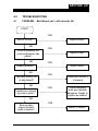
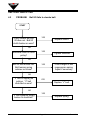
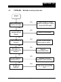
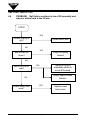
1
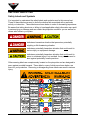
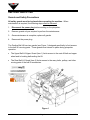
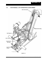
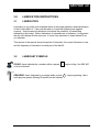
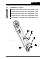
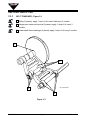
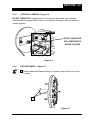
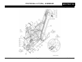
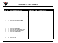
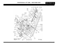
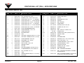
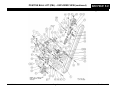
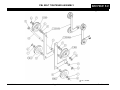
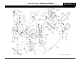
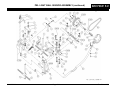
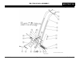
POSITIVE BALL LIFT (PBL)
AMF 90XLi Pinspotter Manual Supplement
PBL ASSEMBLED (REVISED)
400-088-011 Rev. A
ALL RIGHTS RESERVED
All rights to this manual including the diagrams, figures, and technical specifications are
the property of AMF Bowling Products, Inc. Reproduction or transmission of any of the
material contained in this manual without the prior written permission of AMF Bowling
Products, Inc. is strictly prohibited. All of the product information in this manual was
carefully prepared based on the latest information available and was believed to be
correct at the time of printing. While every effort has been made to ensure accuracy,
this publication may inadvertently contain typographical errors, inaccuracies, or errors of
omission. AMF Bowling Products, Inc. cannot be held responsible for any claims
resulting from these errors.
4
DOCUMENT UPDATES
AMF Bowling Products, Inc. reserves the right to revise and/or update this manual at
any time without obligation to notify any person or entity of such revision. The
document number, revision level, and date below indicate the edition of this manual.
5
TRADEMARK NOTICES
AMF and the AMF logo are the registered trademarks of AMF Bowling Worldwide, Inc.
6
AMF TECHNICAL SUPPORT
Technical Support: (International) 804.730.4000 - (Domestic) 1-800-342-5263
AMF Bowling Products, Inc.
8100 AMF Drive
Mechanicsville, Va. 23111
Copyright © 2001, 2004 AMF Bowling Products, Inc.
Document #400-088-011 Rev. A
Issued Date: 10/29/2004
AMF
Positive Ball Lift (PBL) Manual, Rev. A
400-088-011
SUMMARY OF CHANGES
Change No.
ECR No.
List of Effective Pages
Page
All
Change No.
Original
Effective Date
10/29/2004
Table of Contents
SAFETY ......................................................................................................................
1.0
INTRODUCTION .......................................................................................................... 1-1
1.1
2.0
3.0
4.0
1
How To Use This Manual ............................................................................... 1-1
POSITIVE BALL LIFT OPERATION & ADJUSTMENT .............................................. 2-1
2.1
Positive Ball Lift Description ......................................................................... 2-2
2.2
Positive Ball Lift Removal .............................................................................. 2-2
2.3
Positive Ball Lift Installation .......................................................................... 2-2
2.4
Positive Ball Lift Belt Adjustment ................................................................. 2-3
2.5
Sensor Assembly Operation .......................................................................... 2-4
2.6
Sensor Adjustment ......................................................................................... 2-4
2.7
Rudder and Sensor Adjustment .................................................................... 2-5
2.8
Trip Cam Adjustment ..................................................................................... 2-7
2.9
Reset Cam Adjustment .................................................................................. 2-7
2.10
Checking the Reset Cams .............................................................................. 2-8
2.11
Positive Ball Lift Assembly Adjustment ....................................................... 2-9
2.12
Lift Arm Adjustment .................................................................................... 2-10
2.13
Rubber Bumper Adjustment ....................................................................... 2-11
LUBRICATION INSTRUCTIONS .................................................................................. 3-1
3.1
Lubrication ...................................................................................................... 3-1
3.2
Lubricant Symbols ......................................................................................... 3-1
3.3
Lubrication Points .......................................................................................... 3-2
3.3.1
Positive Ball Lift .................................................................................. 3-2
3.3.2
Positive Ball Lift .................................................................................. 3-3
3.3.3
Belt Tensioner ..................................................................................... 3-4
3.3.4
Light Ball Sensor ................................................................................ 3-5
3.3.5
Ratchet Wheel ..................................................................................... 3-5
TROUBLESHOOTING ................................................................................................. 4-1
4.1
Ball idles at exit - will not enter lift ................................................................ 4-1
4.2
Ball lift fails to elevate ball ............................................................................. 4-2
4.3
Ball fails to roll up track rails ......................................................................... 4-3
4.4
Ball yo-yos on track rails ............................................................................... 4-4
4.5
Ball becomes airborne at top of track rail assembly ................................... 4-5
Table of Contents
5.0
4.6
Ball wobbles on track rail assembly ............................................................ 4-6
4.7
Ball lift belt leaves V-groove of sheaves ...................................................... 4-7
4.8
Rudder slaps ball back onto carpet ............................................................. 4-8
4.9
Sensor fails to clear pin jams ....................................................................... 4-9
DRAWINGS & PARTS LISTS ..................................................................................... 5-1
Positive Ball Lift - assembled ............................................................................. 5-2
Positive Ball Lift - exploded view ....................................................................... 5-4
Positive Ball Lift - exploded view (continued) ................................................... 5-6
PBL Belt Tensioner Assembly ............................................................................ 5-8
PBL Belt Tightener Assembly .......................................................................... 5-10
PBL Ratchet Drive Assembly ........................................................................... 5-12
PBL Light Ball Sensor Assembly .................................................................... 5-14
PBL Light Ball Sensor Assembly (continued) ................................................ 5-16
PBL Track Rail Assembly ................................................................................. 5-18
SAFETY
Safety
SAFETY
General Safety Guidelines
AMF believes strongly in its commitment to safety. Proper service and repair are
important to the safety of the mechanic as well as the safe, reliable operation of
the pinspotters. Please read, understand, and follow all of the recommended
safety procedures presented in this manual.
The procedures recommended and described in this technical manual are
effective methods of performing service and repair. Some of these procedures
require the use of tools specially designed for this purpose.
•
Properly trained personnel should be present whenever maintenance is being
performed on a pinspotter.
•
No unauthorized personnel should be allowed in the pit area.
•
Keep in mind that the pinspotter performs a series of mechanical motions and
electrical actions during each cycle, and that bodily injury could result should
personnel enter the machine when power is on. When working in a
pinspotter, it is recommended that power also be turned off on adjacent
machines.
•
The belts and pulleys of the Positive Ball Lift can present a severe pinching
hazard. Whenever possible, turn off both associated pinspotters before
performing maintenance, and exercise caution when working around
operating equipment.
•
Remember that safety must remain your first priority at all times.
•
Safety goggles, ear protection, and steel-toed shoes are recommended
whenever any work is being performed on a pinspotter.
•
Wearing loose clothing or jewelry is NOT RECOMMENDED when operating or
maintaining the machinery.
400-088-011
Page 1
Rev. Date 10/04
AMF 90XLi PINSPOTTER
Safety Labels and Symbols
It is important to understand the safety labels and symbols used in this manual set.
Three of these labels are used to show the relative risk associated with a particular
activity or instruction. These labels are shown below in order of decreasing importance.
Be aware that taking shortcuts or failing to heed applicable safety information can result
in serious injury or damage and can render the pinspotter unsafe for you as well as for
others who follow in your place.
indicates a hazardous situation that presents a potentially
crippling or life-threatening situation.
indicates a potentially hazardous situation that could result in
serious injury or equipment damage.
indicates a potentially hazardous situation that could result in
minor to moderate injury if not avoided. It may also be used to
alert against potentially unsafe practices.
Other warning labels are conspicuously located on the pinspotter and are designed to
warn against possible hazards. These labels, some of which are shown below, are
there for your protection. Removing or disregarding these labels can result in serious
injury.
400-088-011
Page 2
Rev. Date 10/04
SAFETY
Safety
– Refer to the Service Manual before performing
maintenance or repair.
– Caution! Severe pinching hazard - belts.
It is also important to understand that the use of these symbols and labels is not allinclusive because it is impossible to warn of all the possible hazards and consequences
that could result from failure to follow these instructions. Trained and competent
bowling center mechanics are able to recognize and avoid potentially hazardous
situations.
400-088-011
Page 3
Rev. Date 10/04
AMF 90XLi PINSPOTTER
Guards and Safety Precautions
All safety guards must be in place before operating the machine. When
maintenance is required, the following steps must be followed:
1.
Disconnect the power plug before working on the pinspotter.
2.
Remove guards only as required to perform the maintenance.
3.
Once maintenance is complete, replace all guards.
4.
Reconnect the power plug.
The Positive Ball Lift has two guards (see Figure 1) designed specifically to limit access
to the ball lift’s moving parts. These guards must remain in place during pinspotter
operation.
•
The Upper Ball Lift Upper Guard (item 1) limits access to the main lift belt and upper
wheel and to bowling balls exiting the lift.
•
The Rear Ball Lift Guard (item 2) limits access to the many belts, pulleys, and other
moving parts of the ball lift mechanism.
1
2
Figure 1
400-088-011
Page 4
Rev. Date 10/04
SECTION 1.0
Introduction
1.0
INTRODUCTION
1.1
How To Use This Manual
This manual is provided for use by trained and authorized bowling center mechanics in
conjunction with the adjustment, operation, and maintenance of Positive Ball Lift units
installed in AMF pinspotters. The purpose of this manual supplement is to consolidate
all of the applicable PBL information into one easy-to-use document making finding the
information you need simpler and faster when compared to having the information
scattered throughout the pinspotter manual.
This manual does not cover the initial installation of the Positive Ball Lift, but does cover
removal and reinstallation of the unit for maintenance and adjustment. Refer to the
drawings at the back of this manual for detailed views of the Positive Ball Lift’s
construction.
There are six parts to this manual supplement: Safety, Introduction, Operation &
Adjustments, Lubrication, Troubleshooting, and Drawings and Parts Lists.
•
The Safety section provides information on precautions that should be taken when
working in and around the Positive Ball Lift, including examples of safety labels and
symbols used on the pinspotter to indicate potential hazards.
•
The Introduction Section outlines the manual.
•
The Operation and Adjustment Section gives step-by-step instructions for setting up
and adjusting the PBL, as well as information related to the operation of the unit.
•
The lubrication Section provides drawings and information concerning the proper
lubrication of the PBL. Maintaining the PBL in accordance with this section can help
attain maximum component life and trouble-free operation.
•
The Drawings and Parts Lists Section is designed to be an invaluable tool for
identifying parts and part numbers for maintenance and repair of the unit.
This manual is intended to be a supplement to, and is included with, the AMF 90XLi
Pinspotter Manual Set.
Refer to the Safety Section of this manual before
proceeding with Ball Lift maintenance.
400-088-011
Page 1-1
Rev. Date 10/04
AMF 90XLi PINSPOTTER
This Page Intentionally Left Blank
400-088-011
Page 1-2
Rev. 10/04
SECTION 2.0
Operation & Adjustment
2.0
POSITIVE BALL LIFT OPERATION & ADJUSTMENT
Ball Lift Assembly
Track Rail Assembly
Belt Tightener
Belt Tensioner
Ratchet Drive
Assembly
Light Ball
Sensor
PBL ASSEMBLED (REVISED)
Figure 2-1
400-088-011
Page 2-1
Rev. Date 10/04
AMF 90XLi PINSPOTTER
2.1
Positive Ball Lift Description
The purpose of the ball lift is to raise the ball high enough to permit a gravity return to
the bowler. The 90XLi Pinspotter’s Positive Ball Lift is equipped with AMF’s Gripper Ball
Lift system ensuring reliable operation even with today’s heavily oiled lanes. The ball lift
consists of a number of separate assemblies that work together to achieve the desired
result. These assemblies are (refer to Figure 2-1):
•
Ball Lift Assembly
•
Track Rail Assembly
•
Light Ball Sensor
•
Belt Tensioner
•
Ratchet Drive Assembly
•
Belt Tightener
2.2
Positive Ball Lift Removal
1.
Turn off power to both pinspotters.
2.
Remove the upper and rear ball lift guards.
3.
Remove the two springs and extension rods, the two belt tightener springs, and the
ratchet drive belt tensioner spring from between the pinspotters.
4.
Remove the carpet drive belts, the ratchet drive belt, and the upper paddle drive
belt from the PBL pulleys.
5.
Remove the clamp studs from the upper and lower ball lift shaft mounting brackets,
and lift the ball lift assembly out of pinspotter.
2.3
Positive Ball Lift Installation
1.
Place the upper ball lift assembly shaft in the upper support brackets on the
kickback plates.
2.
Place all V-belts in position on the lift pulleys.
3.
Put the lower ball lift shaft in the lower support brackets.
4.
Install the clamp studs keeping the nuts loose.
5.
Adjust the upper and lower shafts to center the lift with the track rails in accordance
with Section 2.11
6.
Verify that the ball lift is aligned with the track rails. Adjustment is required when
the ball lift shaft support brackets on the kickback plates are not aligned directly
across from each other or are not at the same height.
400-088-011
Page 2-2
Rev. 10/04
SECTION 2.0
Operation & Adjustment
7.
If the ball lift is not aligned with the track rails:
a.
Rotate the ball lift support shafts so that the slots in the adjustable plates are in
line with the direction of offset between the support brackets on the kickback
plates (see Figure 2-2).
Offset
PBL SHAFT ASSEMBLY
Figure 2-2
b.
Tighten the nuts on the clamp studs.
c.
Loosen the nuts on the upper and lower adjustable shaft assemblies, and
adjust the ball lift support shafts within the slots of the adjustable plates until
the ball lift and track rails are in alignment.
d.
Tighten the nuts on the upper and lower adjustable support shaft plates.
8.
If an offset adjustment was made, or if a different ball lift is being installed, verify
correct bumper height adjustment in accordance with Section 2.13.
9.
Install all drive belts, springs, and spring extensions.
10. Reinstall the upper and rear guards.
11. Test the ball lift by running several balls through it to verify smooth operation, that
the belt does not slip, and that the unit remains properly aligned.
2.4
1.
Positive Ball Lift Belt Adjustment
If the lift belt rubs against the tube assembly
when a ball is being elevated, adjustment is
necessary.
Use a spanner wrench and
rotate the upper spring retainer until the
length of the spring between the lower
retainer and the upper washer is 4-1/8
inches (see Figure 2-3). This should result
in the correct belt tension.
4-1/8”
Figure 2-3
400-088-011
Page 2-3
Rev. Date 10/04
AMF 90XLi PINSPOTTER
2.5
Sensor Assembly Operation
The cam follower roller must be
low enough so that it will slide
under the rudder cams when
paddle movement is blocked,
but high enough so that the
rudder cams will lock behind it
in the power drive position (see
Figure 2.4). Washers are
included in the assembly for
fine tuning the height of the cam
follower roller.
Figure 2-4
2.6
1.
Sensor Adjustment
If the height of the cam follower must be
adjusted:
a. Remove the light ball sensor from the
machine.
b. Disconnect the support plate tension spring.
c. Add or remove washers, as needed,
between the cam follower and the support
plate.
d. Reconnect the support plate tension spring.
e. Reinstall the light ball sensor in the
pinspotter.
Mounting Bolts
2.
Support Arm
SENSOR - BACK VIEW
The ball lift sensor support arm should be
centered between the side plates. Measure
with a ruler. Loosen the mounting bolts and
adjust if necessary (see Figure 2-5).
Figure 2-5
400-088-011
Page 2-4
Rev. 10/04
SECTION 2.0
Operation & Adjustment
2.7
Rudder and Sensor Adjustment
1.
Remove the retaining nut from the crank pin and save (see Figure 2-6).
2.
Remove the rod assembly from the crank pin and swing it out of the way so that the
sensor assembly can be moved manually.
Reset Cams
Rod
Assembly
Rudder Drive Pulley
Adjusting Plate
Sensor
Assembly
Crank Pin
Pivot Crank Nut
SENSOR - ADJUSTMENTS
Figure 2-6
3.
Remove both reset cams.
4.
Loosen the pivot crank nut and turn the adjusting plate to the full clockwise position,
then tighten the pivot crank nut to prevent the adjusting plate from moving.
5.
Move the rudder arm back and forth, so that it touches the rubber bumper on each
side plate. The arm should move freely with no interference. If the paddle is not
centered in the door opening, it may be necessary to adjust the length of the rudder
arm for front-to-back alignment and/or shim the rudder arm support bracket for
vertical alignment as shown in Figure 2-7.
400-088-011
Page 2-5
Rev. Date 10/04
AMF 90XLi PINSPOTTER
Shim Here to Raise
Rudder Arm
Rudder Arm Length
Adjustment Bolt
SENSOR - BACK VIEW
Shim Here to
Lower Rudder Arm
Figure 2-7
6.
If not done previously, disconnect the spring from the belt tensioner and remove the
belt from the rudder drive pulley.
7.
Reattach the rod assembly to the crank pin and pivot the sensor assembly by
manually rotating the rudder drive pulley to observe the travel of the rudder arm.
8.
Adjust the length of the rod assembly so that the rudder arm swings equally to the
left and right of the center position. Tighten the rod’s jam nuts.
NOTE: Lengthening the rod provides more travel towards the odd machine while
shortening the rod provides more travel towards the even machine. The
rod assembly has right-hand threads on both ends, so the rod end must
be removed from the crank pin to make adjustments.
9.
Loosen the pivot crank nut on the crank plate and rotate the plate in a
counterclockwise manner to increase the overall stroke of the rudder arm. The
correct adjustment is achieved when the rudder arm touches each rubber bumper
on the left and right side plates with equal force without actuating the trip cam
follower when the drive pulley is rotated. There should be a little overtravel (1/8
inch) on each side. Tighten the pivot crank nut.
10. Rotate the rudder drive pulley to recheck travel. If the rudder hits one bumper and
not the other, repeat Steps 8 & 9.
400-088-011
Page 2-6
Rev. 10/04
SECTION 2.0
Operation & Adjustment
2.8
Trip Cam Adjustment
1.
Turn the drive pulley to place the rudder in the center of its travel (center of ball lift).
2.
Push the trip cam followers forward as far as they will go. There should be a
1/8-inch gap on each side between the trip cam and rollers (see Figure 2-8).
Rudder at
Center of Ball
Return
Trip Cam
1/8”
Trip Cam Bolts
1/8”
Trip Cam
Follower
SENSOR - BACK VIEW 2
Figure 2-8
3.
To adjust, loosen the trip cam bolts, reposition the cam, and retighten the bolts.
4.
Recheck the clearance after tightening.
2.9
Reset Cam Adjustment
1.
Rotate the drive pulley to place the rudder arm as far left as it will go, striking the
bumper. Hold this position.
2.
Install the left reset cam and move its angled surface to touch the trip cam follower.
Tighten the cam’s mounting bolt.
3.
Repeat Steps 1 and 2 for the right side reset cam.
400-088-011
Page 2-7
Rev. Date 10/04
AMF 90XLi PINSPOTTER
2.10
Checking the Reset Cams
1.
Manually rotate the rudder drive pulley. While the sensor is moving back and forth,
move one of the trip cam follower rollers towards the rear of the machine. Continue
rotating the drive pulley until the roller contacts the reset cam, returning the trip cam
follower roller to its normal (forward) position.
2.
Manually push the trip cam follower roller forward to check that it has fully returned
to its forward position.
3.
If the trip cam follower roller has fully returned to its forward position, the reset cam
is properly adjusted. If the roller has not fully returned to its forward position, adjust
the reset cam inward a small amount and repeat Steps 1 and 2.
4.
Check and, as necessary, adjust the other trip cam follower roller in the same
manner.
5.
Install the belt on the rudder drive pulley.
6.
Replace the spring on the belt tensioner.
7.
On the chassis, turn the Back End switch ON.
Keep your hands away from belts, pulleys, and other rotating
equipment! Failure to do so can result in severe personal
injury to the hands and arms.
8.
Apply power to the machine.
9.
Retest the operation of the trip cam follower rollers. Use a screwdriver or wooden
stick in the open end of the rudder arm to cause the rudder to actuate each roller. If
the roller does not return to its forward position properly during the subsequent
sweep of the assembly, turn power to the machine OFF and readjust the reset cam.
10. Retest under power until both reset cam settings are correct.
400-088-011
Page 2-8
Rev. 10/04
SECTION 2.0
Operation & Adjustment
2.11
Positive Ball Lift Assembly Adjustment
1. The Positive Ball lift assembly must be centered between the return rails (see
Figure 2-9). To adjust, loosen the nuts on the four clamp studs in the upper and
lower mounting brackets, adjust the lift from side to side as needed, and
retighten the nuts.
Return Rails
Figure 2-9
2. The Positive Ball Lift belt tension spring should be compressed to 4-1/8 ±1/8”
for proper tension on the lift belt (see Figure 2-10). Take this measurement
between the top edge of the spring and the upper edge of the lower spring
retainer. Adjust by tightening or loosening the upper retaining ring using a
spanner wrench.
4-1/8”
Figure 2-10
400-088-011
Page 2-9
Rev. Date 10/04
AMF 90XLi PINSPOTTER
2.12
Lift Arm Adjustment
1. Measure the height of the lift arm above the door weldment (see Figure 2-11). This
distance should be no more than 1/8 inch. Adjust this gap by adjusting the length of
the rod that connects between the lift arm and the ratchet drive assembly (see
Figure 2-12). The rod has right hand threads on both ends, so one end of the rod
must be disconnected in order to make the adjustment. Shortening the rod raises
the lift arm, lengthening the rod lowers the lift arm. Tighten the jam nuts after
completing the adjustment.
Figure 2-11
Ratchet Drive Assembly
Rod End
Adjustment Rod
LIFT
ARM
ADJUSTMNET
LIFT
ARM
ADJUSTMENT
Figure 2-12
400-088-011
Page 2-10
Rev. 10/04
SECTION 2.0
Operation & Adjustment
2.13
Rubber Bumper Adjustment
1.
Place a bowling ball on the lift arm assembly (see Figure 2-13).
2.
Measure the clearance between the ball and the ball lift belt. This clearance should
be between 3/8 and 1/2 inch. The increase in clearance from earlier units is
needed because of the thicker rail covers of the new Gripper ball return.
3/8” to 1/2”
clearance
PBL CLEARANCE
Figure 2-13
3.
Adjust this clearance by adjusting the height of the rubber bumpers (see Figure 2-14).
Following adjustment, tighten the jam nuts.
Rubber Bumper
Jam Nut
Figure 2-14
400-088-011
Page 2-11
Rev. Date 10/04
AMF 90XLi PINSPOTTER
This Page Intentionally Left Blank
400-088-011
Page 2-12
Rev. 10/04
SECTION 3.0
Lubrication
3.0
LUBRICATION INSTRUCTIONS
3.1
LUBRICATION
Lubrication is one of the most important items in the proper operation and maintenance
of the Positive Ball Lift. Care must be taken to insure that lubricants are applied
correctly. Avoid excessive lubrication to minimize the possibility of transmitting
lubricants to the bowler. Before lubrication of exposed parts or surfaces, it is important
that the old lubricant first be removed. It is also very important to clean the ball lift as
you lubricate.
This section of the manual shows the points of lubrication, the correct lubricants to use,
and the frequency of lubrication for each part of the ball lift.
3.2
LUBRICANT SYMBOLS
OILING: Items indicated by a number within a square 1
oil as the lubricant.
GREASING: Items indicated by a number within a circle 1
multi-purpose grease (Bearing Guard #2) as the lubricant.
400-088-011
Page 3-1
require oiling. Use SAE #10
require greasing. Use a
Rev. Date 10/04
AMF 90XLi PINSPOTTER
3.3
LUBRICATION POINTS
3.3.1
POSITIVE BALL LIFT (PBL) - Figure 3-1
1 Rudder arm pivot points (2 places): apply 2 drops of oil every 3 months.
2 Paddle drive pulley shaft (2 places): apply 2 drops of oil every 3 months.
3 Pin wheel belt tensioner (2 places): apply 2 drops of oil every 3 months.
4 PBL lift arm flange bearing (2 places): apply 2 drops of oil every 3 months.
5 Carpet belt tensioner assembly (6 places): apply 2 drops of oil every 2
months.
1
3
5
1
Figure 4-1
2
PBL ASSEMBLED (REVISED)
1
4
Apply grease (with Grease Gun) every 6 months.
400-088-011
Page 3-2
Rev. 10/04
SECTION 3.0
Lubrication
3.3.2
POSITIVE BALL LIFT - Figure 3-2
1 Idler pulley (2 places): apply 2 drops of oil to each side every 3 months.
2 Lower yoke pivot points (4 places): apply 2 drops of oil every 3 months.
3 Upper yoke pivot points (4 places): apply 2 drops of oil every 3 months.
4 Upper yoke upper shaft (2 places): apply 2 drops of oil every 3 months.
5 Lower yoke upper shaft (2 places): apply 2 drops of oil every 3 months.
4
3
2
Figure 3-2
1
5
PBL
400-088-011
Page 3-3
Rev. Date 10/04
AMF 90XLi PINSPOTTER
3.3.3
BELT TENSIONER - Figure 3-3
1 Pulley (2 places): apply 1 drop of oil to each side every 3 months.
2 Hanger arm center pivot points (6 places): apply 1 drop of oil every 3
months.
3 Lower shaft sleeve bearings (4 places): apply 1 drop of oil every 3 months.
1
2
2
BELT TENSIONER
3
Figure 3-3
400-088-011
Page 3-4
Rev. 10/04
SECTION 3.0
Lubrication
3.3.4
LIGHT BALL SENSOR - Figure 3-4
DO NOT LUBRICATE component parts of the trip cam and rudder cam assembly,
outlined within the square below. Friction is required in this area to allow the sensor to
operate properly.
DO NOT LUBRICATE
ANY COMPONENTS
WITHIN THIS BOX
SENSOR - FRONT VIEW
Figure 3-4
3.3.5
RATCHET WHEEL - Figure 3-5
1 Ratchet wheel shaft flange bearings (2 places): apply 2 drops of oil every
3 months.
1
RATCHET WHEEL
400-088-011
Page 3-5
Figure 3-5
Rev. Date 10/04
AMF 90XLi PINSPOTTER
This Page Intentionally Left Blank
400-088-011
Page 3-6
Rev. 10/04
SECTION 4.0
Troubleshooting
4.0
TROUBLESHOOTING
4.1
PROBLEM:
Ball idles at exit – will not enter lift.
START
YES
Ball lift too low?
NO
Lift arm assembly not
centered between side
plates?
NO
Adjust bumper.
YES
Adjust lift arm.
YES
Rudder jammed?
NO
Light Ball Sensor out
of adjustment?
NO
Adjust rudder.
YES
YES
Interference caused
by bounce plate?
Adjust per Section 2
of manual.
Check mounting
bolts and vibration
dampener. Repair or
replace as needed.
NO
Bounce plate
support bracket
loose or broken?
400-088-011
YES
Repair or replace.
Page 4-1
Rev. Date 10/04
AMF 90XLi PINSPOTTER
4.2
PROBLEM:
Ball lift fails to elevate ball.
START
Pulley rotates but ball
lift does not. Ball lift
clutch broken or worn?
YES
Replace clutch.
NO
Setscrew loose on drive
pulley?
YES
Tighten setscrew.
NO
Ball lift belt tension low.
Belt tension spring
retainer nut loose?
YES
Check length of belt
compression spring.
Adjust if necessary.
NO
“V” belt is slipping on
pulleys. “V” belt
stretched or worn?
YES
Replace “V” belt.
NO
“V” belt tightener spring
broken or stretched?
400-088-011
YES
Replace spring.
Page 4-2
Rev. 10/04
SECTION 4.0
Troubleshooting
4.3
PROBLEM:
Ball fails to roll up track rails.
START
Ball lift assembly
position too high?
YES
Adjust height of rubber
stops as required to obtain
proper ball lift height.
NO
Lift arm does not
engage ratchet
clutch?
YES
Reset lift arm height.
NO
Ball bounces on
lift arm?
YES
Reset lift arm height.
Reset sensor travel.
NO
Ball spins on
lower track cover
section?
YES
Replace
polyurethane tube.
NO
YES
Lift arm sticks in
raised position?
Replace rod ends.
Replace crank assembly.
NO
YES
Oil and dirt
buildup?
400-088-011
Clean track rail and PBL
belt.
Page 4-3
Rev. Date 10/04
AMF 90XLi PINSPOTTER
4.4
PROBLEM: Ball fails to continue to top of lift assembly and
stops or slides back to the lift arm.
START
YES
Lift belt is dirty or
oily?
Clean ball lift belt.
NO
YES
Ball lift belt too
loose?
Adjust lift spring
tension.
NO
Ball lift too far to
rear?
Adjust lift at both
adjustable shafts to
move lift forward.
YES
Adjust upper tension
bracket.
NO
Lower track cover
worn?
400-088-011
YES
Page 4-4
Replace lower
track cover.
Rev. 10/04
SECTION 4.0
Troubleshooting
4.5
PROBLEM:
assembly.
Ball becomes airborne at top of track rail
START
Insufficient shock
travel?
YES
Change shock
mount position or
shock assembly.
NO
Lift belt to track rail
clearance is less
than 4.5 inches?
YES
Reset ball lift
height.
NO
Sticking shock
absorber?
YES
Replace shock
assembly.
NO
YES
Ball lift not
centered?
Center lift.
NO
Track rail and
down sweep not
centered between
machines?
400-088-011
YES
Page 4-5
Center unit at top
of ball lift.
Rev. Date 10/04
AMF 90XLi PINSPOTTER
4.6
PROBLEM:
Ball wobbles on track rail assembly.
START
Ball lift assembly
not centered
between track
rails?
400-088-011
YES
Page 4-6
Center ball lift
assembly at both
top and bottom of
track rail assembly.
Rev. 10/04
SECTION 4.0
Troubleshooting
4.7
PROBLEM:
Ball lift belt leaves V-groove of sheaves.
START
Ball lift assembly not
centered between
track rails?
YES
Center ball lift
assembly at both top
and bottom of track
rail assembly.
NO
Insufficient belt
tension?
YES
Adjust length of ball
lift spring.
NO
Ball lift belt worn?
400-088-011
YES
Page 4-7
Replace Belt.
Rev. Date 10/04
AMF 90XLi PINSPOTTER
4.8
PROBLEM:
Rudder slaps ball back onto carpet.
START
YES
Rudder cams fail to
reset to proper height?
Reset rudder
cams.
NO
YES
Rudder cams fail to
clear top of 1-inch
diameter follower?
Remove washers from
under 1-inch diameter
cam follower.
NO
YES
Ball lift assembly too
low?
Adjust height of rubber
stops as required to
obtain proper ball lift
height.
NO
Trip cam followers fail
to hold position when
actuated?
YES
NO
Increase compression of
spring by placing a
retainer ring between the
D-washer & retainer ring
at the lower end of the
weldment.
YES
Sensor oily or dirty and
needs adjusting?
400-088-011
Disassemble, clean and
replace (do not
lubricate). Readjust.
Page 4-8
Rev. 10/04
SECTION 4.0
Troubleshooting
4.9
PROBLEM:
Sensor fails to clear pin jams.
START
Rudder cams fail to
engage 1-inch
diameter follower?
YES
Reset trip cam.
NO
Sensor spring is too
weak?
YES
Replace sensor
spring.
NO
Excessive rudder camto-top-of-cam follower
clearance?
YES
Add washers under
1-inch diameter cam
follower.
NO
Sensor assembly is
oily?
400-088-011
YES
Page 4-9
Remove sensor assembly,
disassemble, clean, and
replace. (Do not lubricate.)
Rev. Date 10/04
AMF 90XLi PINSPOTTER
This Page Intentionally Left Blank
400-088-011
Page 4-10
Rev. 10/04
SECTION 5.0
DRAWINGS
&
PARTS LISTS
400-088-011
Page 5-1
Rev. 10/04
POSITIVE BALL LIFT (PBL) - ASSEMBLED
SECTION 5.0
Drawings & Parts Lists
POSITIVE BALL LIFT
ASSEMBLED (REVISED)
400-088-011
Page 5-2
Rev. Date 10/04
POSITIVE BALL LIFT (PBL) - ASSEMBLED
AMF 90XLi PINSPOTTER
ITEM QTY PART #
DESCRIPTION
ITEM QTY PART #
DESCRIPTION
1
3
000-024-673
SPRING
27
1
070-011-035
STRAP
2
2
090-004-520
V- BELT, CARPET DRIVE
28
1
070-011-039
RATCHET ASSEMBLY
3
6
831-565-002
NUT, HEX, 3/8 - 16
29
1
070-011-064
V- BELT, RATCHET DRIVE
4
6
000-024-610
CLAMP STUD
30
1
090-002-016
SPRING EXTENSION
5
1
070-011-052
BALL LIFT ASSEMBLY (see next illustration)
31
1
070-011-810
BELT TIGHTENER
6
1
000-021-813
WIPER SUPPORT
32
2
000-026-031
SPRING
33
1
070-011-034
EXTENSION ROD
7
1
070-004-669
BALL WIPER CLOTH
8
2
000-021-814
WIPER CLOTH RING
9
1
000-029-629
DOWN SWEEP WELDMENT
10
1
070-004-670
DUST TRAP
11
4
070-004-654
TRACK SUPPORT BRACKET
12
8
809-865-285
SCREW, HEX, 3/8 - 16 X 1-3/4
13
74
948-767-132
WASHER, 13/32 X 13/16 X 1/16
14
20
844-065-002
NUT, STOVER LOCK, 3/8 - 16
15
1
088-001-235
TRACK RAIL ASSEMBLY
16
4
070-008-212
SPACER
17
1
070-008-207
RAIL WELDMENT
18
1
070-011-148
V- BELT, PADDLE DRIVE, UPPER
19
1
090-002-015
BELT TENSIONER ASSEMBLY
20
1
070-011-178
CRANK ASSEMBLY
21
1
070-011-147
V- BELT, PADDLE DRIVE, LOWER
22
1
070-011-120
LIGHT BALL SENSOR ASSEMBLY
23
12
809-857-165
SCREW, HEX, 5/16 - 18 X 1
24
8
948-761-112
WASHER, 11/32 X 11/16 X 1/16
25
12
844-057-002
NUT, STOVER LOCK, 5/16 - 18
26
14
000-029-910
SHIM
400-088-011
Page 5-3
Rev. Date 10/04
POSITIVE BALL LIFT (PBL) – EXPLODED VIEW
SECTION 5.0
Drawings & Parts Lists
400-088-011
Page 5-4
Rev. Date 10/04
POSITIVE BALL LIFT (PBL) – EXPLODED VIEW
AMF 90XLi PINSPOTTER
ITEM QTY PART #
DESCRIPTION
ITEM QTY PART #
1
4
840-057-002
NUT, STOVER LOCK, 5/16
2
4
948-761-112
WASHER, FLAT, 11/32 X 11/16 X 1/16
21
*3
2
070-006-320
SHAFT ASSY. ADJ. 9 ½ “ - 11 “ SPACING
22
2
070-006-329
SHAFT ASSY ADJ. 11“ - “12-5/8” SPACING
23
2
070-006-333
SHAFT ASSY. ADJ. 12-5/8“ - 14” SPACING
2
070-005-325
SHAFT ASSY. FXD. 9 ½ “ - 11” SPACING
2
070-006-328
SHAFT ASSY. FXD. 11” - “12-5/8” SPACING
*4
20
1
DESCRIPTION
070-001-995
UPPER YOKE w/NUT
2
000-024-661
PULLEY
4
806-265-160
SETSCREW, 3/8 - 16 X 1
4
070-006-748
SPACER
24
4
610-905-704
BALL BEARING
25
1
610-900-711
UPPER SHAFT
26
4
951-164-002
WASHER, SPLIT LOCK, 3/8
2
070-006-330
SHAFT ASSY. FXD. 12-5/8“ - 14” SPACING
27
2
809-865-165
SCREW, HEX, 3/8 -16 X 1
5
1
070-011-289
SHOCK ABSORBER BRACKET
28
1
000-029-613
RAIL
6
2
900-112-203
SLEEVE BEARING, .753 X 1-1/4
29
1
088-001-233
BELT, NO-SLIP, V-GUIDE, FLAT
7
1
070-011-002
LOWER SUPPORT
30
1
8
2
919-005-800
RETAINING RING
30A
1
000-021-408
IDLER PULLEY ASSY (includes 30 & 43)
9
2
see 9A & 9A1
LINK
31
1
070-008-218
SPACER, LONG
see 30A
IDLER PULLEY
9A
1
000-024-720
LINK ASSY, UPPER (includes 6, 9, 10, & 51)
32
1
000-029-660
SHAFT
9A1
1
000-024-651
LINK ASSY, LOWER (includes: 9, 10 & 37)
33
2
919-005-600
RETAINING RING
10
4
900-110-121
SLEEVE BEARING, .628 X 3/4
34
2
948-983-212
WASHER, FLAT, 1-5/16 X 21/32 X .093
11
4
807-265-060
SETSCREW, 3/8 - 16 X 3/8
35
1
839-549-002
NUT, FLEX LOCK, ¼ - 20
12
1
000-024-606
UPPER SUPPORT
36
2
900-212-161
FLANGED BEARING, .753 X 1.003 X 1
13
16
937-000-000
RIVET, STEEL, 1/4 X 11/32
37
2
900-112-161
SLEEVE BEARING, .753 X 1
14
1
710-501-007
GREASE FITTING
38
1
070-011-040
RATCHET ROLLER
15
1
000-024-647
ROLLER
39
1
809-865-445
SCREW, HEX, 3/8 - 16 X 2¾
15A
1
000-024-650
ROLLER ASSEMBLY (includes 15 & 16)
40
1
919-005-200
RETAINING RING
16
1
900-206-081
FLANGED BEARING, .378 X .688 X 1/2
17
4
856-070-002
NUT, FLANGED, 7/16 - 20
18
1
000-024-607
TUBE
18A
1
070-011-004
TUBE & SUPPORT ASSY (incl. 7, 12, 13, & 18)
19
1
000-024-648
PIVOT PIN
41
1
070-008-215
BELT TIGHTENER WELDMENT
41A
1
070-011-041
BELT TIGHTENER WELDMENT ASSEMBLY
(includes 36 & 41)
41A1
1
070-011-042
BELT TIGHTENER ASSEMBLY (includes 30A,
31, 35, 38, 40, 41A, 42, 44, 49, & 50)
* Items 3 & 4 vary in length according to the space between the right and left pinspotters.
400-088-011
Page 5-5
Rev. Date 10/04
POSITIVE BALL LIFT (PBL) – EXPLODED VIEW (continued)
SECTION 5.0
Drawings & Parts Lists
400-088-011
Page 5-6
Rev. Date 10/04
POSITIVE BALL LIFT (PBL) – EXPLODED VIEW (continued)
AMF 90XLi PINSPOTTER
ITEM QTY PART #
DESCRIPTION
ITEM QTY PART #
DESCRIPTION
42
1
070-008-217
SHORT SPACER
66
2
090-003-401
CLUTCH RACE, LONG
43
1
900-208-161
FLANGED BEARING, .503 x .875 x 1
67
1
070-011-796
LOWER SHAFT
44
1
146-005-277
WASHER, COUNTERSUNK, 9/32 x 7/8 x 1/8
N/A
700-107-170
LOCTITE #601 (applied to item 63)
45
1
000-028-737
SHAFT
N/A
700-107-146
ADHESIVE, LOCTITE TL242 (apply to item 11)
46
1
000-024-603
SPRING
47
1
000-024-608
UPPER RETAINER
48
1
000-024-605
LOWER RETAINER
49
1
808-849-565
SCREW, FLAT HEAD, ¼ - 20 X 3-1/2
50
1
070-007-192
WASHER
51
1
000-024-716
SPRING HOLDER
52
2
000-027-996
RUBBER CUSHION
53
1
831-566-002
NUT, HEX, 3/8 - 24
54
2
000-027-998
RETAINER
55
2
000-028-057
RETAINER
56
2
070-008-212
SPACER
57
1
070-008-211
SHEAVE
58
1
000-024-811
PULLEY ASSEMBLY, R.H.
59
1
839-665-002
NUT, FLEX LOCK, 3/8 - 16
60
1
000-024-659
LOWER YOKE
61
1
000-029-661
SHOCK ABSORBER
61A
1
070-011-323
SHOCK ABSORBER ASSEMBLY (includes
5, 32, 33, 34, 52, 53, 54, 55, 56, & 61)
62
6
000-027-642
WASHER
63
2
070-007-291
CLUTCH BEARING
64
1
000-024-812
PULLEY ASSEMBLY, L.H.
65
1
070-008-210
SHEAVE
400-088-011
Page 5-7
Rev. Date 10/04
PBL BELT TENSIONER ASSEMBLY
SECTION 5.0
Drawings & Parts Lists
400-088-011
Page 5-8
Rev. Date 10/04
PBL BELT TENSIONER ASSEMBLY
AMF 90XLi PINSPOTTER
ITEM QTY PART #
DESCRIPTION
1
1
000-029-605
PIVOT SHAFT
2
6
900-110-081
SLEEVE BEARING, .628 X .878 X .5
see 3A
ITEM QTY PART #
3
2
3A
2
000-029-659
HANGER ARM ASSY (includes items 2 & 3)
4
4
919-005-600
RETAINING RING
5
1
000-029-606
PIVOT SHAFT, SHORT
HANGER ARM
6
1
070-011-147
V-BELT, PADDLE DRIVE, LOWER
7
1
919-005-500
RETAINING RING
8
2
900-208-120
BEARING
9
1
070-011-131
PULLEY WELDMENT
10
1
000-027-264
SPACER
11
1
090-002-016
SPRING EXTENSION
12
1
090-002-014
SHAFT
13
1
919-005-900
RETAINING RING
14
1
000-026-031
SPRING
400-088-011
DESCRIPTION
Page 5-9
Rev. Date 10/04
PBL BELT TIGHTENER ASSEMBLY
SECTION 5.0
Drawings & Parts Lists
400-088-011
Page 5-10
Rev. Date 10/04
PBL BELT TIGHTENER ASSEMBLY
AMF 90XLi PINSPOTTER
ITEM QTY PART #
DESCRIPTION
ITEM QTY PART #
1
1
see 1A & 1A1
ARM ASSY WELDMENT, L.H. MACHINE
1A
1
070-011-530
ARM ASSY, L.H. MACHINE (includes 1 & 3)
1A1
1
070-011-524
BELT TIGHTENER, L.H. MACHINE (includes
1, 3, 4, 5, 6, 7, 8, & 10)
2
1
see 2A & 2A1
ARM ASSY WELDMENT, R.H. MACHINE
2A
2A1
1
1
070-011-527
070-011-523
ARM ASSY, R.H. MACHINE (includes 2 & 3)
BELT TIGHTENER, R.H. MACHINE (includes
2, 3, 4, 5, 6, 7, 8, & 10)
3
4
900-112-121
SLEEVE BEARING, .753 X .75
4
2
701-316-041
THRUST BEARING, .51 X 1 X 1/16
5
4
900-208-161
FLANGED BEARING, .503 X .875
6
2
6A
2
000-021-408
IDLER PULLEY ASSY (includes 5 & 6)
7
4
948-975-172
WASHER, FLAT, 1-1/16 X 17/32 X 3/32
see 6A
IDLER PULLEY
8
4
963-600-002
X-WASHER, 1/4
9
2
919-005-800
RETAINING RING
10
2
070-011-526
IDLER SHEAVE
10A
2
070-011-525
IDLER SHEAVE ASSY (includes 5 & 10)
11
1
000-029-603
SHAFT
400-088-011
DESCRIPTION
Page 5-11
Rev. Date 10/04
PBL RATCHET DRIVE ASSEMBLY
SECTION 5.0
Drawings & Parts Lists
400-088-011
Page 5-12
Rev. Date 10/04
PBL RATCHET DRIVE ASSEMBLY
AMF 90XLi PINSPOTTER
ITEM QTY PART #
DESCRIPTION
ITEM QTY PART #
DESCRIPTION
1
1
919-005-600
RETAINING RING
25
1
070-011-029
NUT
2
1
070-011-028
WASHER
26
1
070-011-064
V-BELT, RATCHET DRIVE
3
1
070-011-027
SHAFT
27
0-26*
948-767-132
WASHER, FLAT, 13/32 X 13/16 X 1/16
4
1
907-000-200
KEY
28
2
070-008-212
SPACER
5
2
900-212-161
FLANGED BEARING, .753 X 1.003 X 1
29
2
948-761-112
WASHER, FLAT, 11/32 X 11/16 X 1/16
6
1
070-011-009
BEARING HOUSING WELDMENT
30
2
844-057-002
NUT, STOVER LOCK, 5/16 - 18
6A
1
070-011-036
BEARING & HOUSING ASSY (includes 5 & 6)
7
16
839-549-002
NUT, FLEX LOCK, ¼ - 20
8
1
070-011-033
PULLEY
9
32
000-026-865
WASHER
10
16
070-011-030
ROLLER
11
16
070-011-031
ROLLER SPACER
12
16
809-849-205
SCREW, HEX, ¼ - 20 X 1¼
13
2
919-000-600
RETAINING RING
14
2
000-024-679
BALL BEARING, .625 X 1.375
15
1
070-011-013
CRANK WELDMENT
15A
1
070-011-037
CRANK ASSY (includes 13, 14, 15, & 16)
16
1
070-006-142
BUMPER
17
3
919-005-200
RETAINING RING
18
3
070-011-040
RATCHET ROLLER
19
1
070-011-217
RATCHET ARM WELDMENT
20
1
838-866-002
NUT, HEX LOCK, 3/8 - 24, THIN
21
1
947-356-617
WASHER, 5/16
22
1
809-965-125
SCREW, HEX, 3/8 - 16 X ¾
23
1
948-964-142
WASHER, FLAT, .375 X .875 X .094
24
1
070-011-032
SPRING
* The number of washers used depends on the spacing between the left and right machines’ kickplates. See installation drawing 610-007-043.
400-088-011
Page 5-13
Rev. Date 10/04
PBL LIGHT BALL SENSOR ASSEMBLY
SECTION 5.0
Drawings & Parts Lists
400-088-011
Page 5-14
Rev. Date 10/04
PBL LIGHT BALL SENSOR ASSEMBLY
AMF 90XLi PINSPOTTER
ITEM QTY PART #
DESCRIPTION
ITEM QTY PART #
DESCRIPTION
1
4
809-857-165
SCREW, HEX, 5/16 - 18 X 1
23
1
070-011-146
PADDLE
2
2
000-022-869
WASHER
24
2
000-021-423
COLLAR WITH SETSCREW
3
1
070-011-418
TRIP CAM
25
2
000-021-427
FLANGED BEARING, .629 X .878 X 1/8
4
1
070-006-728
CAM FOLLOWER
26
1
000-027-264
SPACER
27
1
27A
1
5
4
949-100-002
WASHER, FLAT, 59/64 X 13/32 X 1/16
6
1
070-011-068
LINK WELDMENT
see 27A
7
1
809-865-205
SCREW, HEX, 3/8 - 16 X 1¼
28
2
913-448-120
SPRING PIN, ¼ X ¾
8
2
070-011-107
TRIP ARM (RESET CAM)
29
1
070-011-098
SLEEVE
070-011-406
RUDDER CAM, R.H.
RUDDER CAM ASSY, R.H. (incl. 27, 28 & 49)
9
1
802-865-996
SCREW, HEX, 3/8 - 16 X 9½
30
3
919-005-200
RETAINING RING
10
3
000-029-611
WASHER, UNIBALL BEARING
31
2
070-011-626
TRIP ARM ASSEMBLY
11
1
840-065-002
NUT, FLEX LOCK, 3/8 -16, THIN
32
2
070-011-273
TAB
12
1
090-005-258
ROD ASSEMBLY
33
6
900-208-091
FLANGED BEARING, .503 X .690 X 9/16
13
1
838-866-002
NUT, HEX LOCK, 3/8 - 24
34
2
722-985-512
COMPRESSION SPRING
14
2
070-011-096
ROLLER
35
2
900-205-081
FLANGED BEARING, .315 X .44 X 1/2
14A
2
070-011-105
ROLLER ASSEMBLY (includes 14 & 35)
36
1
809-857-880
SCREW, HEX, 5/16 - 18 X 5-1/2
15
2
070-011-077
TRIP FINGER
37
2
090-007-276
BRACKET
16
2
722-971-522
COMPRESSION SPRING
38
1
070-011-040
RATCHET ROLLER
17
4
844-057-002
NUT, STOVER LOCK, 5/16 - 18
39
1
844-070-002
NUT, STOVER LOCK, 7/16 - 20
18
3
948-761-112
WASHER, 11/16 X11/32 X 1/16
40
3
070-011-108
WASHER
19
1
070-011-097
CRANK PULLEY
41
3
919-005-500
RETAINING RING
19A
1
070-011-178
RUDDER DRIVE CRANK ASSY (includes
13, 17, 18, 19, 20 & 63)
42
1
000-026-031
SPRING
43
2
809-849-125
SCREW, HEX, ¼ - 20 x ¾
20
1
070-011-092
CRANK SHAFT WELDMENT
44
1
070-011-299
SENSOR BRACE
21
1
000-029-697
ADJUSTMENT TUBE
45
2
844-049-002
NUT, STOVER LOCK, ¼ - 20
21A
1
000-029-696
ADJUSTMENT TUBE ASSY (includes 21 & 25)
22
1
070-011-148
V-BELT, PADDLE DRIVE, UPPER
400-088-011
Page 5-15
46
1
070-011-067
RUDDER ARM SUPPORT
46A
1
070-011-066
RUDDER ARM SUPPORT ASSY (incl. 46 & 59)
Rev. Date 10/04
PBL LIGHT BALL SENSOR ASSEMBLY (continued)
SECTION 5.0
Drawings & Parts Lists
400-088-011
Page 5-16
Rev. Date 10/04
PBL LIGHT BALL SENSOR ASSEMBLY (continued)
AMF 90XLi PINSPOTTER
ITEM QTY PART #
DESCRIPTION
ITEM QTY PART #
47
1
070-011-100
CAM SENSOR WELDMENT
47A
1
070-011-110
CAM SENSOR ASSY (includes 33 & 47)
48
1
070-011-099
CAM
49
4
900-208-161
FLANGED BEARING, .503 X .875
50
1
50A
1
070-011-407
see 50A
RUDDER CAM ASSY, L.H. (incl. 28, 49 & 50)
51
1
809-865-405
SCREW, HEX, 3/8 - 16 X 2½
52
1
070-011-121
PLUG
53
2
948-767-132
WASHER, FLAT, 13/16 X 13/32 X 1/16
54
1
844-065-002
NUT, FLEX LOCK, 3/8 - 16
55
1
070-011-122
RUDDER ARM
56
1
907-000-900
KEY
RUDDER CAM, L.H.
57
1
831-573-002
NUT, HEX, 1/2 - 13
58
1
000-024-616
CLAMP STUD
59
4
900-212-201
FLANGED BEARING, .753 X 1 X 1.25
60
1
000-024-615
SHAFT
61
1
070-011-079
RUDDER DRIVE WELDMENT
61A
1
070-011-080
RUDDER DRIVE ASSY (incl. 33, 59 & 61)
62
2
070-011-151
SPACER
63
1
070-011-225
CRANK ADJUSTMENT PLATE WELDMENT
64
1
809-865-165
SCREW, HEX, 3/8 - 16 X 1
400-088-011
DESCRIPTION
Page 5-17
Rev. Date 10/04
PBL TRACK RAIL ASSEMBLY
SECTION 5.0
Drawings & Parts Lists
(ITEM
12
)
14A1
PBL TRACK RAIL ASSEMBLY (REVISED)
400-088-011
Page 5-18
Rev. Date 10/04
PBL TRACK RAIL ASSEMBLY
AMF 90XLi PINSPOTTER
ITEM QTY PART #
DESCRIPTION
1
2
809-865-165
SCREW, HEX, 3/8 - 16 X 1
2
2
951-164-002
WASHER, SPLIT LOCK, 3/8
3
1
000-021-813
WIPER SUPPORT
4
2
088-001-232
RAIL COVER, BLACK
5
2
000-024-666
TRACK RAIL WELDMENT
6
2
088-001-231
RAIL COVER, CLEAR
ITEM QTY PART #
7
2
088-001-230
THIMBLE
8
2
810-365-401
SCREW, SOCKET HEAD CAP, 3/8 - 16 X 2-1/2
9
1
070-011-063
SHAFT
10
2
844-065-002
NUT, STOVER LOCK, 3/8 - 16
11
2
844-057-002
NUT, STOVER LOCK, 5/16 - 18
12
0-22***
948-767-132
WASHER, FLAT, 13/32 X 13/16 X 1/16
13
2
900-210-161
FLANGED BEARING, .628 x 1
14
1
070-011-411
LIFT ARM WELDMENT
14A
1
070-011-412
LIFT ARM ASSEMBLY (includes 13 & 14)
14A1
1
070-011-413
LIFT ASSEMBLY (incl. 9, 10, 14A, 15, 20 & 22)
15
4
090-002-024
CRADLE LINER
16
1
838-866-002
NUT, HEX, 3/8 - 24
17
1
090-005-259
ROD ASSEMBLY
18
1
070-011-218
LEVER ARM WELDMENT
19
2
808-857-280
SCREW, FLAT HEAD, 5/16 - 18 x 1-3/4
20
1
809-865-992
SCREW, HEX, 3/8 - 16 X 9
21
1
958-584-002
WASHER, LOCK, 3/8
22
1
070-008-191
BALL LIFT BRACKET
23
1
000-024-668
TRACK SUPPORT BRACKET WELDMENT
DESCRIPTION
***From 0 to 22 washers may be needed for spacing. See installation drawing 610-007-043.
400-088-011
Page 5-19
Rev. Date 10/04