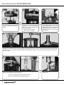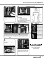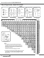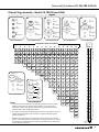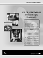
1
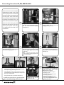
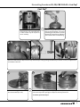
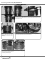
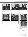
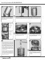
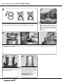
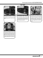
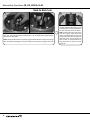
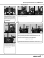
GRUNDFOS CR SERVICE MANUAL CR, CRI, CRN 10•15•20 Dismantling & Reassembly CONTENTS Dismantling Procedures.......................................................Page 2 When Should A Part Be Replaced ?............................................... Page 8 Reassembly Procedures....................................................... Page 9 Setting The Coupling Height......................................................... Page 15 Order of Stage Assembly: CR, CRI, CRN 10.................................Page 16 Order of Stage Assembly: CR, CRI, CRN Low NPSH 10............. Page 17 Order of Stage Assembly: CRNE 10 SF.........................................Page 18 Order of Stage Assembly: CR, CRI, CRN 15/20...........................Page 19 Order of Stage Assembly: CR, CRN Low NPSH 15/20.............. Page 20 Order of Stage Assembly: CRN15/20 SF..................................... Page 21 TORQUES Position Number 7a Coupling Guard Screw..................1.5 ft.-lbs./2 Nm 9 Coupling Hex Screw 5 mm M6 Screw........................10 ft.-lbs./13 Nm 6 mm M8 Screw....................... 23 ft.-lbs./31 Nm 8 mm M10 Screw....................46 ft.-lbs./62 Nm 26b Strap Bolt 13 mm M8 x 25 mm...................11 ft.-lbs./15 Nm 28 Motor Bolt 9/16" UNC 3/8" Bolt.................10 ft.-lbs./13 Nm 3/4" UNC 1/2" Bolt................... 23 ft.-lbs./31 Nm 36 Staybolt Nut CR, CRI........................................59 ft.-lbs./80 Nm CRN........................................... 74 ft.-lbs./100 Nm 67 Shaft Lock Nut...........................16.3 ft.-lbs./22 Nm 1 05 (a,b) Shaft Seal 41 mm Nut.................................26 ft.-lbs./35 Nm 113 2.5 mm Set Screw.....................2 ft.-lbs./2.5 Nm Dismantling Procedures CR, CRI, CRN 10•15•20 These instructions cover the complete 2 1 dismantling and repair of the pump after the pump has been isolated from the system. Before removing the pump from the system, make sure all valves are closed. Relieve any built up pressure by opening the vent plug screw. The power source should be turned off and locked out before starting any work. Using a slotted Screwdriver or TORX® tip T20, remove Coupling Guard Screws (Pos. 7a). Then, remove the Coupling Guards (Pos. 7). Remove the 5, 6 or 8 mm Hex Head Coupling Bolts (Pos. 9) from the Coupling Halves (Pos. 10a). 3 4 5 Remove Coupling Halves. Insert a slotted Screwdriver in Coupling gap and twist to free Coupling Half. To free, remove remaining Coupling Half. Strike Coupling Half with a rubber mallet on upper edge. Remove shaft pin (Pos. 10). Remove the 9/16" Head UNC 3/8" or 3/4" Head UNC 1/2" Motor Bolts (Pos. 28) and lift the motor off the Motor Stool (Pos. 2). Removal of field wiring to the motor wires may be required. Color coding or numbering the wires will aid in reinstallation. NOTE: If you have multiple pumps, do not interchange coupling components... they are a matched set. 6 8 Remove the cartridge Shaft Seal (Pos. 105) by: ·Loosening the three 2.5 mm Shaft Seal Securing Allen Screws (Pos. 113) approximately 1/2 to 1 turn. 7 ·Using 00SV2107 or a 41 mm deep socket, fully unscrew the Shaft Seal from the Motor Stool (Pos. 2) or Pump Head (Pos. 77) on I and N models. ·Sliding the Shaft Seal up and off the Shaft (Pos. 51). For Shaft Seal replacement only, go to Reassembly, step 24. For full dismantling, continue to step 7. 2 Remove the four 24 mm Staybolt Nuts (Pos. 36) and Washers (Pos. 66a). Remove the Motor Stool (Pos. 2) and Pump Head (Pos. 77) on I and N models. (Light upward blows with a rubber mallet may be required.) • If the pump is a standard unit, skip to Dismantling, step 23. • For Cool -Top® type/equipped pumps, see Dismantling, steps 9 to 13. • Pumps built with a Back-to-Back Seal, see Dismantling, steps 14 to 17. • Pumps built with Tandem/Quench Seal, see Dismantling, steps 18 to 22. Dismantling Procedures CR, CRI, CRN 10•15•20 – Cool-Top® Cool-Top® 9 10 Remove the Cool-Top® assembly/Pump Head Cover (Pos. 77a). Light blows with a rubber mallet may be required to loosen assembly. Before removing the Disk Plate (Pos. 79a) from the Pump Head (Pos. 77), inspect the Bushing (Pos. 79b). If worn, use a Flat Blade Punch or Special Punch, 00SV2127, and a mallet to drive out the Bushing. 11 Remove the Disk Plate (Pos. 79a) from the Pump Head Cover (Pos. 77a) by pushing outward with your thumb. If stuck, use a Nylon Punch and a Mallet to drive out. 12 13 Remove the O-ring (Pos. 37c & 109a) from the Disk Plate (Pos. 79a). Remove Sleeve O-ring (Pos. 37) from the pump Head Cover (Pos. 77a). Then remove the PTFE Stack Compression Springs (Pos. 60a) from the Pump Head Cover. To continue, proceed to step 23. 3 Dismantling Procedures CR, CRI, CRN 10•15•20 Back-to-Back Seal 14 (View from a cutaway pump) Loosen and remove the plug to allow access to Shaft Seal securing screw. Insert a 2.5 mm allen wrench to loosen (approximately 1/2 to 1 turn) the three Set Screws (Pos. 113) of the Inboard Seal (Pos. 105b). 15 16 Remove the Pump Head Cover (Pos. 77a). Light blows with a rubber mallet may be required to loosen assembly. Flip the Pump Head Cover over to remove Shaft Seal (Pos. 105b). Using 00SV2107 or 41 mm Deep Socket, loosen and unscrew the Shaft Seal. 17 Remove the Sleeve O-Ring (Pos. 37) and the PTFE Stack Compression Springs (Pos. 60) from the Pump Head Cover (Pos. 77a). To continue, proceed to step 23. 4 Dismantling Procedures CR, CRI, CRN 10•15•20 Tandem Seal 18 19 Loosen (approximately 1/2 to 1 turn) the three 2.5 mm Set Screws (Pos. 113) of the Inboard Seal (Pos. 105b). Use specialty tool, 00SV2107, a 41 mm Deep Socket, or an Open Ring Spanner to loosen. 20 21 Remove the Pump Head Cover (Pos. 77a). Light blows with a rubber mallet may be required to loosen assembly. Finish removal of Shaft Seal (Pos. 105b) from Pump Head Cover (Pos. 77a). Flip the Pump Head Cover over and go to step 22. 22 Remove the Sleeve O-Ring (Pos. 37) and the PTFE Stack Compression Springs (Pos. 60) from the Pump Head Cover (Pos. 77a). To continue, proceed to step 23. 5 Dismantling Procedures CR, CRI, CRN 10•15•20 23 24 Grab the shaft and lift impeller stack out of the pump. If it is stuck, a light blow with a rubber mallet may be needed to jolt the stack free. Place the Holder for Shaft, 00SV0040, in a vise. With the shaft pin inserted into the shaft, place the impeller stack into the shaft holder. Tighten vise. Using a 13 mm wrench, remove the Chamber Stack Strap Bolt (Pos. 26b), Washer (Pos. 26c), and Strap (Pos. 26a). 25 Remove the 26 27 Using a 13 mm wrench, remove the Shaft Lock Nut (Pos. 67), Lock Washer (Pos. 66) and Splined Spacer (Pos. 64c). Lift the Impeller (Pos. 49a) off the shaft. If it comes off freely, proceed to step 29. If it is stuck and cannot be removed by hand, proceed to step 28. Suction Inlet Connector (Pos. 44). NOTE: This may come apart in two pieces (Pos. 44a & 44b). 28 29 Move the shaft into a hole of the shaft holder through which it can pass freely. Screw the Punch for Dismantling Shaft (material #00SV0234) onto the threaded section of shaft. Using a hammer, drive punch down past the hub of the first impeller. Noting chart instructions in step 30, remove each impeller (Pos. 49a) and Chamber with bearing (Pos. 4a) and Chamber (Pos. 4). Repeat these steps until you get down to the last impeller. At that time, gently knock the punch down through the hub area, make sure to catch the shaft as it falls free. Go to step 31. 6 Remove the Chamber with bearing (Pos. 4a) or Chamber (Pos. 4). If it is stuck to the rest of the stack, pry it loose by inserting a screwdriver between the chambers. Dismantling Procedures CR, CRI, CRN 10•15•20 30 31 32 The dismantling procedures from this point will depend on the type of pump and number of stages it contains. Beginning on page 16, refer to the charts in the Reassembly Procedures to determine what you can expect with the pump you are working on. Remove all the Bearing Rings (Pos. 47a) and Spacers (Pos. 64 a, c, d) you encounter while repeating steps 27-29. Continue until you remove the last impeller. To remove Seal Ring (Pos. 45), insert a slotted screwdriver in relief slot of Seal Ring Retainer (Pos. 65) and twist or use Puller 00SV0239. Remove the shaft and examine for damage. At that point, continue... 33 34 Remove the four Stack Compression Springs (Pos. 60) from the Motor Stool (Pos. 2) or Pump Head (Pos. 22). Remove, Sleeve O-rings (Pos. 37) in the Motor Stool (Pos. 2) or Pump Head (Pos. 77) and the Pump Housing (Pos. 6). If the unit leaked around the Sleeve (Pos. 55), removal of the Sleeve may be required. Grip Staybolts (Pos. 26) diagonally. Using your thumbs, press against the Sleeve to release it from the Pump Housing (Pos. 6). Lift off sleeve. (Rocking or light upward blows with a rubber mallet may be required.) 35 Wear Rings (Pos. 49c) can be removed on CR/CRI/CRN 15 and 20 models. Impellers (Pos. 49a) use Puller 00SV2091 and Support 00SV0043 to work Wear Ring off of impeller. THE PUMP IS NOW COMPLETELY DISASSEMBLED. 7 Dismantling Procedures CR, CRI, CRN 10•15•20 When Should A Part Be Replaced ? Part Position(s) Minimum Operating Condition Motor Stool 2 Excessive pitting of these castings could cause leaks. Rusted castings should have all seating areas cleaned to ensure proper seating of O-rings. Suction/Discharge6 Chamber Chambers } 4a, 4 Same as for impellers. The maximum inside diameter for the bearing in position 4a SIC is 23.55 (Bronze & Graflon is 22.02 mm). If a groove can be seen or felt, the chamber should be replaced. Neck Ring 45 Should be free of visible wear on the inside edges Inside diameter for CR10 = 44.01 to 45.04 Inside diameter for CR15 & 20 = 59.84 to 60.02 Bearing ring 47a Minimum outside diameter SIC is 23.4 mm (TC is 21.874 mm). If a groove can be seen or felt, the bearing should be replaced. Impellers 49 Should be free from physical markings except for the guide vane welds. The eyelet or contact surface for the Neck Ring should not show any signs of wear. If worn, replace impeller on CR, CRI, CRN10 or Wear Ring only on CR, CRI, CRN 15 and 20. (1) Cavitation the implosion of vapor "bubbles" within the impeller stack. Make sure the Net Positive Suction Head Available for the pump meets the minimum Net Positive Suction Head Required for the pump when running at the required flow. (2) Improper coupling height. If the coupling is not set to the proper height (see steps 29 to 31 of the Reassembly procedures) the impellers are not suspended as they should be, causing them to rub against the chambers, causing wear. Shaft 51 Smooth area at the top of shaft should be free of fitting grooves. Spline should not be worn. Sleeve 55 Should not be pitted or cracked. Stack Compression Spring 60 & 60a Should not be reused...replace. Spacers & Clamp 64, 64a, 64c, 66, 66b, 69 Should show no signs of gouging or wear at bottom or top. Lock Nut 67 Should not be reused....replace. Lock Washers 66 Should not be reused....replace. O-rings 37a, 38, 68, 100, 102, 109a&b Should be soft and pliable with no visible scars. Since they are easily damaged and fairly inexpensive, it is recommended they be replaced whenever the pump is disassembled. Shaft Seal 105 & 105b Seals cannot be disassembled; should be replaced when repairing /rebuilding the pump. Bushing in Disk 79b Plate 79a If bushing is scored, replace Bushing. If the inner bore of Disk is damaged, replace Disk. Refer to the Parts List and Kits section for a list of material numbers and spare pare kits. 8 Reassembly Procedures CR, CRI, CRN 10•15•20 1 Place Sleeve O-ring (Pos. 37) into recessed area of the Motor Stool (Pos. 2) for CR models, or into the Pump Head (Pos. 77) for CRI, CRN models. Install Sleeve O-ring (Pos. 37b) into Pump Head Cover (Pos. 77a) for CRI, CRN, Cool-Top®, Back-to-Back Seal, Tandem Seal models. Install O-ring into Suction/Discharge Pump Housing (Pos. 6). Note specialty O-ring (Pos. 37b) will always be installed in the lower "Hot" section of the pump of Cool-Top® models. Also install Stack Compression Springs (Pos. 60) for CR, CRI, CRN into Motor Stool or Pump Head Cover. NOTE: Cool-Top® models require two sets of four Stack Compression Springs. The PTFE will always be placed in the lower "Hot" section of pump to press against the stack assembly (Pos. 80). 2 3 Replace any Seal Ring (Pos. 45) in the Chambers (Pos. 4, 4a, and 5a). Inner edge must face downward (see diagram). Snap Seal Ring Retainer (Pos. 65) into place. The retainer should not spin on the chamber, and the seal ring should move freely from side to side. Before reusing the original Shaft (Pos. 51), use a light grit emery cloth to smooth away old set screw marks, as these can cut the O-rings in the seal assembly. 4 7 CR, CRI, CRN 15 & 20 ONLY 5 With Shaft Pin (Pos. 10) inserted into the Shaft (Pos. 51), place shaft into Shaft Holder (material #00SV0040). Press new Wear Ring (Pos. 49c) onto Impeller (Pos. 49a). CR, CRI, CRN, use new Impellers if eyelet of Impeller is worn. 6 The reassembly procedures from this point will depend on the type of pump and the number of stages it contains. Refer to diagrams on pages 16-21 to determine the proper sequence of impellers (Pos. 49 or 49a), Chambers (Pos. 4, 4a), Spacers (Pos. 64 a, c, d) and Bearing Ring (Pos. 47a) needed for the pump you are working with. Place the Clamp Spacer (Pos. 64c) onto the shaft. Reassemble these stages in the order shown, beginning with the highest number stage and continue to the first stage. Then, continue.... 9 Reassembly Procedures CR, CRI, CRN 10•15•20 8 9 The Lock Washers (Pos. 66) come as a set. If they become separated, it is important the washers are repositioned correctly as noted in the diagram. The tabs should interlock while the serrated edges both point outward. Place the washers onto the shaft. Lubricate the threaded end of the shaft with an FDA-approved lubricant. Thread the Lock Nut (Pos. 67) onto the shaft and torque to 16.3 ft.-lbs./22 Nm. Use 13 mm Socket, 00SV0091, Ratchet, 00SV0295, Torque Wrench, 00SV0269. 10 Place Suction Inlet Connector (Pos. 44a & b) onto Stack. Insert Straps (Pos. 26a) into slot in Top Chamber (Pos. 3). Place Washers (Pos. 26c) and Strap Bolt (Pos. 26b) on/into the Straps using a 13 mm Socket, 00SV0091, and Torque Wrench, 00SV0292, with Ratchet, 00SV0295, to Torque Bolt to 11 ft.-lbs./15 Nm. 11 12 Spray soapy water on the Sleeve O-rings (Pos. 37). Then lower and press Sleeve (Pos. 55) firmly into place. Lower new Stack Kit (Pos. 80) into the Pump Housing. Make sure it seats fully into the machined recess. (Chamber Straps must be located as pictured, 90° from suction/discharge ports). Standard CR, CRI, CRN models skip to step 22 Cool-Top® models skip to step 13 Back-to-Back Seal models skip to step 17 Tandem Seal models skip to step 19. 10 Reassembly Procedures CR, CRI, CRN 10•15•20 Cool-Top® 13 14 15 If Bushing (Pos. 79b) was removed from Disk Plate (Pos. 79a), use a Punch, 00SV2127, to install Bushing and Retaining Washer (Pos. 79c) into Disc Plate. Place O-rings (Pos. 109a & 37c) onto the Disk Plate (Pos. 79a). Do not roll the O-rings; they should be stretched over and released into place to prevent cutting the material during installation into the housing. Spray soapy solution onto O-rings and housing. Press the plate firmly in place. Before proceeding to step 16, flip the Pump Head over; make sure the PTFE Stack "Compression Springs" (Pos. 60a) and the Sleeve O-ring (Pos. 37b) have been installed from step 1. If they have not been installed, follow the instructions in step 1 (page 9), then proceed to step 16. 16 Position the plugs to the desired location; lower the completed Cool- Top® Pump Head Assembly (Pos. 77a) over the Shaft and seat on the Sleeve (Pos. 55). If it does not freely seat onto the Sleeve, STOP. Remove the Pump Head and turn over. Remove sleeve O-ring and stretch. Replace and reinstall the Pump Head onto Shaft and Sleeve. Skip to step 22. 11 Reassembly Procedures CR, CRI, CRN 10•15•20 Back-to-Back Seal 17 Insert Inboard Seal (Pos. 105b) into the bottom side of the prepped Pump Head Cover (Pos. 77a). Using the specialty tool, 00SV2107, or a 41 mm Deep Socket, tighten/torque seal the 26 ft.-lbs./35Nm. NOTE: If Pump Head Cover has not yet been prepped with PTFE Stack Compression Springs (Pos. 60) and Sleeve O'Ring (Pos. 37) as previously instructed in step 1, page 9, do so now. 12 18 Use care while sliding/lowering completed Back-to-Back Pump Head Cover into place. Firmly seat over sleeve. If it does not freely seat onto sleeve... STOP! Remove the Pump Head Cover, turn over, remove sleeve O-ring and stretch. Reinstall/replace O-ring into Pump Head Cover, then reinstall onto Shaft and sleeve. Do not tighten the three 2.5 mm set screws at this time. This will be done in step 30. Proceed to step 22. Reassembly Procedures CR, CRI, CRN 10•15•20 Tandem Seal 19 20 Position the plugs to the desired location. Lower the completed Pump Head Assembly (Pos. 77a) over the shaft and seat on the Sleeve (Pos. 55). If it does not freely seat onto the sleeve...STOP. Slide the Inboard Seal (Pos. 105b) down the shaft and thread into the pump head. Use specialty tool, 00SV2107, a 41 mm Deep Socket, or an Open Ring Spanner to torque the Inboard Seal to 26 ft.-lbs./35 Nm. Remove the pump head and turn over. Remove sleeve O-ring and stretch. Replace and reinstall the pump head onto shaft and sleeve. 21 OR Alternative to Step 21 An alternative to step 21 is when the special tool 00SV2078 and two 27.5 mm Spacers (96491537) are used with two Staybolt Nuts and Washers. Place tool over Staybolts and seat against Pump Head Assembly (Pos. 77a). Slide 27 mm Spacers down Staybolts. Place Washers and Nuts onto Staybolts and tighten diagonally to: CR, CRI: 59 ft.-lbs. or 80 Nm CRN: 74 ft.-lbs. or 100 Nm Push Shaft down, then tighten the three 2.5 mm Set Screws to 2 ft.-lbs./2.5 Nm. Remove Staybolt Nuts/Washers, 27 mm Spacers, and tool 00SV2078. Proceed to step 22. Push down on the coller area of the Seal, then lift Shaft to create a clearance of 123 mm from the top of the Shaft (Pos. 51) to the top of the Shaft Seal. Tighten the three 2.5 mm set screws to 2 ft.-lbs./2.5 Nm. Proceed to step 22. 13 Reassembly Procedures CR, CRI, CRN 10•15•20 22 23 24 Spray soapy water on the Sleeve O-rings (Pos. 37) in the Motor Stool or CRI, CRN Pump Head. Then lower and fully press in place. Place the Washers (Pos. 66a) over the Staybolts (Pos. 26). Then, lubricate with a light oil. Place the 24 mm Staybolt Nuts (Pos. 36) onto Staybolts and tighten diagonally to: CR, CRI: 59 ft.-lbs. or 80 Nm CRN: 74 ft.-lbs. or 100 Nm Spray soapy water onto the Seal O-ring Seating Surface of the Pump Head and the Shaft (Pos. 51). (If reusing original Shaft, be sure to use Emery tool provided with Seal Kit to remove any burrs on the Shaft. Then, spray with soapy water.) 25 Pushing down on Shaft Seal collar (do not push down on Hex Nut), lower the new Shaft Seal (Pos. 105) over the Shaft. Use specialty tool, 00SV2107, a 41 mm Deep Socket, or an Open Ring Spanner to tighten to 26 ft.-lbs. or 35 Nm. Push the Shaft all the way down (for Tandem Seal models you must continue to apply downward force), then tighten the three 2.5 mm Shaft Seal Securing Allen Screws torque to 2 ft.-lbs. or 2.5 Nm. 26 27 Lower motor onto Motor Stool and/or Spacer (Pos. 1), then install and tighten Motor Bolts (Pos. 28) diagonally to the proper torque. 14 17 ft.-lbs. or 23 Nm for UNC 3/8" bolts (9/16" Head), and 30 ft.-lbs. or 40 Nm for UNC 1/2” bolts (3/4" Head) Place the Shaft Pin (Pos. 10) into the Shaft (Pos. 51). Reassembly Procedures CR, CRI, CRN 10•15•20 28 29 Install Coupling Halves (Pos. 10a). Spray a light machinery oil onto the Coupling Bolts (Pos. 9). Install loosely into the Couplings. Standard Units and Cool Top® Using a screwdriver, lift the Shaft upward. Insert Shaft Seal Spacer tool between Shaft Seal Collar and Hex Nut. Remove the screwdriver and tighten and torque the Coupling Bolts. 5 mm - M6 to 10 ft.-lbs. or 13 Nm 6 mm - M8 to 23 ft.-lbs. or 31 Nm 8 mm - M10 to 46 ft.-lbs. or 62 Nm Ensure the gap between the two Coupling Halves are even (see Diagram -->). 30 Back-to-Back Seal Using a screwdriver, lift the Shaft upward. Insert two of the Spacer tools between Shaft Seal Collar and Hex Nut. Insert a 2.5 mm allen wrench through one of the lower vent port holes and torque the lower inboard seal securing screws to 2.0 ft.-lbs./2.5 Nm. Remove allen wrench and replace plugs (Pos. 23a) into the Pump Head Cover (Pos. 77a). Remove only one Spacer. Then, tighten and torque the Coupling bolts to values in step 29. 32 31 Tandem Seal Spring tension from the seals may have already lifted the Shaft upward. If not, lift the Shaft upward. At this time insert the Shaft Seal Spacer tool. Remove the screwdriver. Ensure the Shaft has moved d o w n wa rd a n d shaft Seal Collar is resting on the tool. Tighten and torque the Coupling bolts to values in step 29. 33 Remove Spacer Tool, then spin the shaft by hand; proceed only if the shaft spins freely. THE PUMP IS NOW COMPLETELY ASSEMBLED. If the shaft does not spin freely: Stop and start over, inspecting the components for any cause of binding. Install the Coupling Guards (Pos. 7) and the Screws (Pos. 7a). Using a Torque Screwdriver, with a slotted or a TORX® tip T20, torque to 1.5 ft.-lbs. or 2 Nm. Open the isolation valves in the system to fully vent and fill the pump. Restore power supply. Place Shaft Seal Spacer tool(s) on to Coupling Guard(s). 15 Reassembly Procedures CR, CRI, CRN 10•15•20 Order of Stage Assembly – Models CR, CRI, CRN 10 Legend A B C 67 Lock Nut E *See Note 1 D 49 Impeller 49 Impeller 49 Impeller 4 Chamber - CPL 3 Top Chamber with Guide Vanes 64d Spacing Pipe 47a Bearing Ring 66 Star Washer 4a Chamber with Bearing 64c Clamp Part Combination A 61 Stop Spacer 61 Stop Spacer Part Combination C Part Combination B 69a Spacing Pipe 69 Spacing Pipe 64 Spacing Pipe 64a Spacing Pipe 3a Top Chamber without Guide Vanes. Slotted for Straps Part Combination E Part Combination D Number of impellers 3 4 5 6 7 8 9 10 12 14 16 17 18 20 22 X A B E X A B D X A B C D X A B C C D X A B C C C D X A B C C C C D X A B C C C C C D X A B C C C C C C D X A B C C C B C C C D X A B C C C C B C C C D X A B C C C C C C B C C C D X A B C C C C C C C C B C C C D X A B C C C C B C C C C C B C C C D X A B C C C C C B C C C C C C B C C C E X A B C C C C C B C C C C C C B C C C D X A B C C C C C C C B C C C C C C B C C C D X A B C C C C C C C C B C C C C C C C B C C C D X 26b Strap Bolt 26c Strap Washer 44b Lower Inlet Part 26a Strap 44a Upper Inlet part with Retainer & Seal Ring End Combination X NOTES: 1. If an impeller is to be permanently removed (pump destaged), the thickness of the impeller back plate/hub area must be compensated for. Use a longer spacer or combination of spacers that equal the thickness of back plate/hub area material. *Substitute E for D when destaging by 1 impeller. 2. Since proper reassembly of the impeller stages must be done "upside down," this chart has been arranged that way for your convenience. Impeller eyelet (opening) faces upward away from vise. 16 Stages 1 2 3 4 Bottom chamber 2 5 6 7 8 9 10 11 12 13 14 15 16 17 18 19 20 21 22 Begin reassembly on this end 1 Reassembly Procedures CR, CRI, CRN 10•15•20 Order of Stage Assembly – Models CR, CRN 10 (Low NPSH) Legend A B- 67 Nut B 49i Impeller Low NPSH 66 Lock Washer 64c Clamp 64d Spacing Pipe 47a Bearing Ring 4b Chamber 64b Spacing Pipe D C 49 Impeller 4a Chamber with Bearing 64e Spacing Pipe Part Combination B Part Combination B- 49 Impeller 4 Chamber 3 Top Chamber withGuide Vane 64 Spacing Pipe 64a Spacing Pipe Part Combination A 49 Impeller Part Combination C 69 Spacing Pipe 6 Stop Spacer Part Combination D Nameplate number of impellers 5 6 7 8 9 10 12 14 16 X A BB D X A BB C D X A BB C C D X A BB C C C D X A BB C C C C D X A BB C B C C C D X A BB C C B C C C D X A BB C C C C B C C C D X A BB C C C C C C B C C C D X A BB C C C C C C C C B C C C D 17 X A BB C C C C E * See Note 1 B 3a C Top Chamber without Guide C X 44b Vane. Slotted Inlet Part Lower for Straps C 26b Screw 69a Spacing Bush 26c C Washer 61 26a C Stop Spacer Strap 26c 26c44d Washer B Washer Spacer Ring Part Combination E C 61 44cSpacer Stop Inlet Part C Upper C End Combination X NOTES: 1. If an impeller is to be permanently removed (pump destaged), the thickness of the E X A BB E impeller back plate/hub area must be compensated for. Use a longer spacer or combination of spacers that equal the thickness of back plate/hub area material. *Substitute E for D when destaging by 1 impeller. 2. Since proper reassembly of the impeller stages must be done "upside down," this chart has been arranged that way for your convenience. Impeller eyelet (opening) faces upward away from vise. 3. Because the low NPSH chamber and impeller are twice the thickness of a standard chamber, it has the performance of two impellers. Physically, there is one less chamber in a stack than the number of stages listed on the pump label (example: CR10-22 only has 21 chambers and impellers). 18 20 22 X A BB C C C C B C C C C C B C C C D X A BB C C C C C B C C C C C C B C C C D X A BB C C C C C C C B C C C C C C B C C C D Stages 1 2 Bottom chamber 4 3 4 5 6 7 8 9 10 11 12 13 14 15 16 17 18 19 20 21 Begin reassembly on this end 3 22 17 Reassembly Procedures CR, CRI, CRN 10•15•20 Order of Stage Assembly – Models CRN 10 SF (Flipped Stack) Legend A B- 46a O-Ring 46 Discharge Part 46b O-Ring 26a Strap 26c Washer 26b Screw Part Combination A B 67 Nut 49 Impeller 66 Lock Washer D C 49 Impeller 64d Spacing Pipe 64c Clamp 47a Bearing Ring 47a Bearing Ring 64a Spacing Pipe 4a Chamber with Bearing 4c Lower Chamber with Bearing 64 Spacing Pipe 64a Spacing Pipe Part Combination B Part Combination B- 4 Chamber Part Combination C 1. If an impeller is to be permanently removed (pump destaged), the thickness of the impeller back plate/hub area must be compensated for. Use a longer spacer or combination of spacers that equal the thickness of back plate/hub area material. 2. Since proper reassembly of the impeller stages must be done "upside down," this chart has been arranged that way for your convenience. Impeller eyelet (opening) faces downward toward vise. 18 A BC C C C C C C C B C C C C C C C B C C C D Stages 1 2 3 4 5 6 7 8 9 10 11 12 13 14 15 16 17 18 19 20 21 22 Bottom chamber A BC C C C C C B C C C C C B C C C D Begin reassembly on this end NOTES: 21 44a Inlet Part Upper 44b Inlet Part 69 Spacing Pipe 61 Stop Spacer Number of impellers 17 49 Impeller Part Combination D Reassembly Procedures CR, CRI, CRN 10•15•20 Order of Stage Assembly – Models CR, CRI, CRN 15 & 20 Legend A- A B B- 67 Nut 67 Lock Nut 66 Lock Washer 66 Star Washer 64c Clamp 64c Clamp 64d Spacing Pipe Part Combination A 49 Impeller 64d Spacing Pipe 64d Spacing Pipe 47a Bearing Ring 47a Bearing Ring 4a Chamber with Bearing 4a Chamber with Bearing 64a Spacing Pipe 64f Spacing Pipe Part Combination B Part Combination A- C 49 Impeller 49 Impeller 4 Chamber - CPL 64 Spacing Pipe Part Combination C Part Combination B- Number of impellers 3 4 X ABE 5 6 7 8 XX X X X X X X X X X X X X X X X A-A- A A-A-A A A-A-A A A-A-A A A-A B B- B B B B B B B B B B B B B B B DE C D C C C C C C C C C C C C C D CDCC CCC CC CC CC D CDCC B CC BC CC D C DC C B CC BC E *See Note 1 D C DC C B C C 49 D C DC C B 3a Impeller Top Chamber without Guide D C DC Vanes. Slotted 3 for Straps Top Chamber D C with Guide 69a Vanes Spacing Pipe D D 69 Spacing Pipe 61 Stop Spacer 61 Stop Spacer Part Combination D X 26b Strap Bolt 26c Strap Washer Part Combination E 44b Lower Inlet Part 26a Strap 44a Upper Inlet part with Retainer & Seal Ring 9 10 12 XX A-A BB CC CC CC BC CC CC CB BC CC CC DC C B C NOTES: 1. If an impeller is to be permanently removed (pump C destaged), the thickness of the impeller back plate/ hub area must be compensated for. Use a longerD spacer or combination of spacers that equal the XX XX A A- A A BB BB CC CC CC CC CC CC CB CC BC CB CC BC CC CC DB C C C DC C B D C C D 14 17 X A B C C C C B C C C C B C C D X A B C C C C C C B C C C C C B C C D Stages Bottom chamber 2 1 2 3 4 5 6 7 8 9 10 Begin reassembly on this end 1 11 12 13 14 15 16 17 thickness of back plate/hub area material. *Substitute E for D when destaging by 1 impeller. 2. Since proper reassembly of the impeller stages must be done "upside down," this chart has been arranged that way for your convenience. Impeller eyelet (opening) faces upward away from vise. End Combination X 19 Reassembly Procedures CR, CRI, CRN 10•15•20 Order of Stage Assembly – Models CR, CRI, CRN 15 & 20 (low NPSH) Legend A A- 67 Nut A+ 67 Nut 66 Lock Washer 66 Lock Washer 64c Clamp 64c Clamp 64e Spacing Pipe 64e Spacing Pipe 64b Spacing Pipe 47a Bearing Ring, HM 64e Spacing Pipe 64e Spacing Pipe 64e Spacing Pipe Part Combination A Part Combination A+ Part Combination A- B 49i Impeller Low NPSH 64b Spacing Pipe 64b Spacing Pipe 47a Bearing Ring, HM 47a Bearing Ring, HM B- 67 Nut 66 Lock Washer 64c Clamp 64e Spacing Pipe 49 Impeller 64d Spacing Pipe 47a Bearing Ring, SiC 47a Bearing Ring, SiC 4a Chamber with Bearing 4a Chamber with Bearing 64a Spacing Pipe 64a Spacing Pipe Part Combination B Part Combination B- Number of impellers 3 4 5 6 7 8 9 10 12 14 X ABE XX XX X X X X X X X X X X X X X XX XX XX X A-A-A+A- A-A+A+A-A-A+A+A-A A+A A A- A A-A-A- A-A AB-B-B-B- B-B- B-B-B-B-B- B-B-B-B- B-B- B-B- B-B- B-B- BDE C D C C C C C C C C C C C C C C C C C C C C D C D C C C C C C C C C C C CC CC CC C D C D C C B C C B C C C CC CC CC C D C DC C B C C B C CB CC BC C E *See Note 1 D D C DC C B C C BC CB CC B 49 D C DC C B C C BC CC C 3a Impeller Top Chamber without D C DC C C C C CB C Guide Vanes. 3 Slotted for Straps Top Chamber D C DB C C B C C with Guide 69a Vanes Spacing Pipe D C DC C C C 69 C B CC B 61 Spacing Pipe Stop Spacer 61 D C DC C Stop Spacer C C C Part Combination E Part Combination D D B D NOTES: X 1. If an impeller is to be permanently removed (pump destaged),C the 26b thickness of the impeller back plate/hub area must be compensated Strap Bolt C for. Use a longer spacer or combination of spacers that equal the 26c 44b Strap Washer thickness of back plate/hub area material. Lower D Inlet Part 26a Strap 44a Upper Inlet part with Retainer & Seal Ring End Combination X 20 *Substitute E for D when destaging by 1 impeller. 2. Since proper reassembly of the impeller stages must be done "upside down," this chart has been arranged that way for your convenience. Impeller eyelet (opening) faces upward away from vise. 3. HM = Hard Metal - Tungsten Carbide 4. SiC = Sintered Silicon Carbide 17 X A BC C C C C C B C C C C C B C C D Stages Bottom chamber 2 1 2 3 4 5 6 7 8 9 10 Begin reassembly on this end 1 11 12 13 14 15 16 17 Reassembly Procedures CR, CRI, CRN 10•15•20 Order of Stage Assembly – Models CRN 15 & 20 SF (Flipped Stack) B- 46a O-Ring 46 Discharge Part 46b O-Ring 26a Strap 26c Washer 26b Screw Part Combination A B 67 Nut 66 Lock Washer 49 Impeller 64d Spacing Pipe 64c Clamp 47a Bearing Ring 47a Bearing Ring 64a Spacing Pipe 4 Chamber 4a Chamber with Bearing 4c Lower Chamber with Bearing 64 Spacing Pipe 64a Spacing Pipe 49 Impeller 44a Inlet Part Upper 44b Inlet Part 69 Spacing Pipe 61 Stop Spacer Part Combination B Part Combination B- D C 49 Impeller Part Combination C Part Combination D Number of impellers A A BA B- BC C C C C C C C C C C B B C C C C B C C C D D C D 11 17 A A BBC C C C C C C B C C CD C C B C C D A BC C C C C C B C C C C C B C C D Stages 1 2 3 4 5 Bottom chamber 9 6 7 8 9 10 11 12 13 14 15 16 Begin reassembly on this end A Legend 17 NOTES: 1. If an impeller is to be permanently removed (pump destaged), the thickness of the impeller back plate/hub area must be compensated for. Use a longer spacer or combination of spacers that equal the thickness of back plate/hub area material. 2. Since proper reassembly of the impeller stages must be done "upside down," this chart has been arranged that way for your convenience. Impeller eyelet (opening) faces downward toward vise. 21 SM-DRC-136 0113 The name Grundfos, the Grundfos logo, and be think innovate are registered trademarks owned by Grundfos Holding A/S, Denmark. All rights reserved worldwide. © Copyright Grundfos Holding A/S GRUNDFOS Pumps Corporation 17100 W. 118th Terrace Olathe, Kansas 66062 Phone: 913.227.3400 Fax: 913.227.3500 www.grundfos.us GRUNDFOS Canada, Inc. 2941 Brighton Road Oakville, Ontario L6H 6C9 Canada Phone: 905.829.9533 Fax: 905.829.9512 Bombas GRUNDFOS de Mexico S.A. de C.V. Boulevard TLC No. 15 Parque Industrial Stiva Aeropuerto Apodaca, N.L. Mexico 66600 Phone: 52.81.8144.4000 Fax: 52.81.8144.4010