1
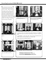
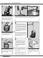
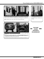
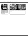
GRUNDFOS CR SERVICE MANUAL CR, CRI, CRN 1S•1•3•5 Dismantling & Reassembly CONTENTS Dismantling Procedures........................................... Page 2 When Should A Part Be Replaced ?............................... Page 8 Reassembly Procedures........................................... Page 9 CR Series Setting The Coupling Height...........................................Page 16 Order of Stage Assembly: CR(I/N) 1S•1•3...................... Page 17 Order of Stage Assembly: CR(N) 3 Low NPSH..............Page 18 Order of Stage Assembly: CRNE 1•3 High Speed........Page 19 Order of Stage Assembly: CR(I/N) 5..............................Page 20 Order of Stage Assembly: CR(N) 5 Low NPSH..............Page 21 TORQUES Position Number 7a Coupling Guard Screw............. 2 ft.-lbs./2.5 Nm 9 Coupling Hex Screw M6 Screw................................10 ft.-lbs./13 Nm M8 Screw...............................20 ft.-lbs./27 Nm M10 Screw............................ 46 ft.-lbs./62 Nm 28 Motor Bolt UNC 3/8" Bolt........................10 ft.-lbs./13 Nm UNC 1/2" Bolt.........................23 ft.-lbs./31 Nm 36 Staybolt Nut CR/CRI....................................29 ft.-lbs./40 Nm CRN.......................................37 ft.-lbs./50.2 Nm 67 105 113 146 147 149 Shaft Lock Nut........................13.3 ft.-lbs./18 Nm Shaft Seal 36 mm Nut............................26 ft.-lbs./35 Nm 2.5 mm Set Screw................. 2 ft.-lbs./2.5 Nm Hex Screw for Pos. 147/148... 6 ft.-lbs./8.13 Nm Stationary Seal Retainer........26 ft.-lbs./35 Nm Connecting Pipe.......................26 ft.-lbs./35 Nm Dismantling Procedures CR, CRI, CRN 1s•1•3•5 These instructions cover the repair of 1 2 Using a screwdriver, remove Coupling Guard Screws (Pos. 7a). Then, remove the Coupling Guards (Pos. 7). Remove the Hex Head Coupling Bolts (Pos. 9) from the Coupling Halves (Pos. 10a). Remove Coupling Halves and the Shaft Pin (Pos. 10). stack after the pump has been isolated from the system. Before removing the pump from the system, make sure all valves are closed. Relieve any built up pressure by opening the vent plug screw. The power source should be turned off and locked out before starting any work. Removal of field wiring to the motor wires may be required. Color coding or numbering the wires will aid in reinstallation. 3 4 Remove the cartridge Shaft Seal (Pos. 105) by: ·Loosening the three 2.5 mm Shaft Seal Securing Allen Screws (Pos. 113). Do not fully remove screws as this may cause the seal assembly to come apart in component form. Remove the Motor Bolts (Pos. 28) and lift the motor off the Motor Stool (Pos. 2). ·Using 00SV2007 or a 36 mm deep socket. Fully unscrew the Shaft Seal from the Motor Stool (Pos. 2) or Pump Head (Pos. 77) on I and N models. ·Slide the Shaft Seal up and off the Shaft (Pos. 51). 5 Remove the four 19 mm Staybolt Nuts (Pos. 36) and Washers (Pos. 66a). 2 6 Remove the Motor Stool (Pos. 2) and Pump Head (Pos. 77) on I and N models. (Light upward blows with a rubber mallet may be required.) • If the pump is a standard unit, skip to step 18. • For Cool Top™ type/equipped pumps, see steps 7 to 9. • Pumps built with a Back-to-Back Seal, see steps 10 to 13. • Pumps built with Tandem/Quench Seal, see steps 14 to 17. Dismantling Procedures CR, CRI, CRN 1s•1•3•5 – Cool Top™ Cool Top™ 7 8 Remove the Cool Top assembly/Pump Head Cover (Pos. 77a). Light blows with a rubber mallet may be required to loosen assembly. If the Disk Plate (Pos. 79) remained in the Pump Head (Pos. 77), use a punch and rubber mallet to drive the plate out. If the Disk Plate remained in the Pump Head Cover (Pos. 77a), use a rubber mallet to free the plate and lift it off. 9 Use a 36 mm wrench or deep socket to loosen. Unscrew the Connecting Pipe (Pos. 149); lift off and check the O-rings (Pos. 109a & b). If damaged, remove. To continue, proceed to step 18. 3 Dismantling Procedures CR, CRI, CRN 1s•1•3•5 – Back-to-Back Seal Back-to-Back Seal 10 NOTE: When performing the next step be aware there is spring tension against the Seal Driver. Loosen, but do not fully remove the two Set Screws (Pos. 113) of the Inboard Seal Driver (Pos. 112a). Slide the driver up and off the shaft. Remove the remaining components: Larger Seal Driver (Pos. 112), Spring (Pos. 108), Small Seal Driver (Pos. 111), O-ring (Pos. 107), Rotating Seal Face (Pos. 104). 11 Remove the Pump Head Cover (Pos. 77a). Light blows with a rubber mallet may be required to loosen assembly. 12 Loosen and remove the three 2.5 mm Hex Screws (Pos. 146). Remove the Stationary Seal Retaining Washer (Pos. 148). Remove the Stationary Seal (Pos. 103) and O-ring (Pos. 102). 13 Use specialty tool, 00SV2007, or a 36 mm deep socket to loosen. Unscrew the Stationary Seal Retainer (Pos. 147). Lift off and check the O-ring (Pos. 109a). If damaged, remove. To continue, proceed to step 18. 4 Dismantling Procedures CR, CRI, CRN 1s•1•3•5 – Tandem/Quench Seal Tandem/Quench Seal 14 15 Loosen the three 2.5 mm Set Screws (Pos. 113) of the Inboard Seal (Pos. 105b). Use specialty tool, 00SV2007, or a 36 mm deep socket to loosen. Unscrew the Inboard Seal. 16 Slide the Inboard Seal (Pos. 105b) up and off the shaft. 17 Remove the Pump Head Cover (Pos. 77a). Light blows with a rubber mallet may be required to loosen assembly. To continue, proceed to step 18. 5 Dismantling Procedures CR, CRI, CRN 1s•1•3•5 18 Grab the shaft and lift impeller stack out of the pump. If it is stuck, a light blow with a rubber mallet may be needed to jolt the stack free. The bottom chamber (Pos. 5a) may remain in the suction/discharge chamber. 20 19 Place the Holder for Shaft (00SV0040) in a vise. With the shaft pin inserted into the shaft, place the impeller stack into the shaft holder. Tighten vise. Using a 13 mm wrench, remove the Lock Nut (Pos. 67), Washer (Pos. 66), and Spacer (Pos. 64a). 21 Move the shaft into a hole of the shaft holder through which it can pass freely. Screw the Punch for Dismantling Shaft (material #00SV0234) onto the threaded section of shaft. Using a hammer, drive punch down past the hub of the first impeller. Noting chart instructions in step 23, remove each impeller (Pos. 49a) and Chamber with bearing (Pos. 4a) and Chamber (Pos. 4). Lift the Impeller (Pos. 49a) off the shaft. If it comes off freely, proceed to step 22. If it is stuck and cannot be removed by hand, proceed to step 21. 22 Repeat these steps until you get down to the last impeller. At that time, gently knock the punch down through the hub area, make sure to catch the shaft as it falls free. Go to step 24. 23 24 The dismantling procedures from this point will depend on the type of pump and number of stages it contains. Beginning on page 17, refer to the charts in the Reassembly Procedures to determine what you can expect with the pump you are working on. Remove the Chamber with bearing (Pos. 4a) or Chamber (Pos. 4). If it is stuck to the rest of the stack, pry it loose by inserting a screwdriver between the chambers. 6 Remove all the Bearing Rings (Pos. 47a) and Spacers (Pos. 64 a, c, d) you encounter while repeating steps 20-22. Continue until you remove the last impeller. Remove the shaft and examine for damage. At that point, continue... Using the Puller for Neck Ring (material #00SV0239) to work the Seal Ring Retainer (Pos. 65), loosen and remove. Remove Seal Ring (Pos. 45). Dismantling Procedures CR, CRI, CRN 1s•1•3•5 25 If the pump shows leakage around the sleeve (Pos. 55), removal of the sleeve may be required. Grip the Staybolts (Pos. 26) diagonally. Using your thumbs, press against the sleeve to release it from the Suction/Discharge pump housing (Pos. 6). Lift off sleeve. NOTE: Light blows with a rubber mallet may be required to free sleeve. 26 If the Bottom Chamber (Pos. 5a) has not already been removed, use a screwdriver to pry it out of the pump housing. 27 Using a screwdriver, remove Corrugated Spring (Pos. 60): For standard CR: remove the Outer Sleeve O-ring (Pos. 37) from the Motor Stool (Pos. 2). THE PUMP IS NOW COMPLETELY DISASSEMBLED! For CRI, CRN, Cool Top, Back-to-Back Seal, or Tandem Seal equipped pumps: remove the O-rings from the Pump Head (Pos. 77) and Pump Head Cover (Pos. 77a). Note: The Corrugated Spring is located in the pump head cover. On all models, remove the Sleeve O-ring from the Suction/Discharge Chamber (Pos. 6). 7 Reassembly Procedures CR, CRI, CRN 1s•1•3•5 When Should A Part Be Replaced ? Part Position(s) Motor Stool 2 Suction/Discharge6 Chamber } Minimum Operating Condition Excessive pitting of these castings could cause leaks. Rusted castings should have all seating areas cleaned to ensure proper seating of O-rings. Chambers 4a, 4 Same as for impellers. The maximum inside diameter for the bearing in position 4a is 17.52 mm. If a groove can be seen or felt, the chamber should be replaced. Neck Ring 45 Should be free of visible wear on the inside edges Inside diameter for CR 1s, 1, & 3 = 30.6 ± .05 mm Inside diameter for CR5 = .25 ± .01 mm Bearing ring 47a Minimum outside diameter is 17.349 mm. If a groove can be seen or felt, the bearing should be replaced. Impellers 49 Should be free from physical markings except for the guide vane welds. The eyelet or contact surface for the Neck Ring should not show any signs of wear. (1) Cavitation the implosion of vapor "bubbles" within the impeller stack. Make sure the Net Positive Suction Head Available for the pump meets the minimum Net Positive Suction Head Required for the pump when running at the required flow. (2) Improper coupling height. If the coupling is not set to the proper height (see step 33 of the Reassembly procedures) the impellers are not suspended as they should be, causing them to rub against the chambers, causing wear. Shaft 51 Smooth area at the top of shaft should be free of fitting grooves. Spline should not be worn. Sleeve 55 Should not be pitted or cracked. Corrugated Spring 60 Should not have any cracks in material. Spacers & Clamp 64, 64a, 64c, 66, 66b, 69 Should show no signs of gouging or wear at bottom or top. Lock Nut 67 Should not be reused....replace. Lock Washers 66 Should not be reused....replace. O-rings 37, 38, 68, 100, 102, 109a&b Should be soft and pliable with no visible scars. Since they are easily damaged and fairly inexpensive, it is recommended they be replaced whenever the pump is disassembled. Shaft Seal 105 Seals mfg. after January, 2003 cannot be disassembled; should be replaced when repairing /rebuilding the pump. Connecting Pipe 149 If bushing is scored....replace. Refer to the Parts List and Kits section for a list of material numbers and spare pare kits. 8 Reassembly Procedures CR, CRI, CRN 1s•1•3•5 1 2 To Install Corrugated Spring (Pos. 60): For standard CR: install into the Motor Stool (Pos. 2). For CRI, CRN: install into Pump Head (Pos. 77) For Cool Top, Back-to-Back Seal, & Tandem Seal: install into the Pump Head Cover (Pos. 77a) Edges of spring must point downward as shown for all models. Place Sleeve O-ring (Pos. 37) into recessed area of the Motor Stool (Pos. 2) for CR models, or into the Pump Head (Pos. 77) for CRI, CRN models. Install Sleeve O-ring (Pos. 37b) into Pump Head Cover (Pos. 77a) for CRI, CRN, Cool Top, Back-to-Back Seal, Tandem Seal models. Install O-ring into Suction/Discharge Pump Housing (Pos. 6). Note specialty O-ring (Pos. 37b) will always be installed in the lower "Hot" section of the pump of Cool Top models. 3 4 Before reusing the original Shaft (Pos. 51), use a light grit emery cloth to smooth away old set screw marks, as these can cut the Replace any Seal Ring (Pos. 45) in the Chambers (Pos. 4, 4a, and 5a). Inner edge must face downward (see diagram). Snap Seal Ring Retainer (Pos. 65) into place. The retainer should not spin on the chamber, and the seal ring should move freely from side to side. 5 6 O-rings in the seal assembly. 7 The reassembly procedures from this point will depend on the type of pump and the number of stages it contains. Refer to diagrams on pages 17-21 to determine the proper sequence of impellers (Pos. 49 or 49a), Chambers (Pos. 4, 4a), Spacers (Pos. 64 a, c, d) and Bearing Ring (Pos. 47a) needed for the pump you are working with. With Shaft Pin (Pos. 10) inserted into the Shaft (Pos. 51), place shaft into Shaft Holder (material #00SV0040). Reassemble these stages in the order shown, beginning with the highest number stage and continue to the first stage. Place the Clamp Spacer (Pos. 64c) onto the shaft. Then, continue.... 9 Reassembly Procedures CR, CRI, CRN 1s•1•3•5 8 9 The Lock Washers (Pos. 66) come as a set. If they become separated, it is important the washers are repositioned correctly as noted in the diagram. The tabs should interlock while the serrated edges both point outward. Place the washers onto the shaft. Lubricate the threaded end of the shaft with an FDA-approved lubricant. Thread the Lock Nut (Pos. 67) onto the shaft and torque to 13.3 ft.-lbs./18 Nm. 10 Spray soapy water on the Sleeve O-rings (Pos. 37 or 37b). Lower and press the Sleeve (Pos. 55) firmly into place. If the sleeve does not slide easily over the O-ring...STOP. Remove the sleeve and sleeve O-ring. Stretch the O-ring, place the O-ring back into the groove of the housing and proceed with sleeve installation. 12 If the Top Guide Vane (Pos. 50a) has not already been placed onto the stack, add this now. Standard CR (I/N) models skip to step 25 Cool Top models skip to step 13 Back-to-Back Seal models skip to step 16 Tandem Seal models skip to step 23. 10 11 After the Bottom Chamber (Pos. 5a) has been placed onto the stack, remove the stack assembly from the shaft holder and turn it over. Lower the stack into the Suction/Discharge pump housing. Reassembly Procedures CR, CRI, CRN 1s•1•3•5 – Cool Top™ Cool Top™ 13 Place O-rings (Pos. 109a & b) onto the Connecting Pipe (Pos. 149). Do not roll the O-rings; they should be stretched over and released into place to prevent cutting the material during installation into the housing. Spray soapy solution onto O-rings and housing. Screw the connection pipe into the prepped Cool Top Assembly/Pump Head Cover (Pos. 77a). Using a 36 mm wrench or deep socket, torque to 26 ft.-lbs./35 Nm. 14 Spray soapy solution into the center hole of the Disk Plate (Pos. 79), and press the plate firmly in place. Before proceeding to step 15, flip the Pump Head over; make sure the Corrugated Spring (Pos. 60) and the Sleeve O-ring (Pos. 37b) have been installed from steps 1 and 2. If they have not been installed, follow the instructions in those steps, then proceed to step 15. 15 Position the plugs to the desired location; lower the completed Cool Top Pump Head Assembly (Pos. 77a) over the shaft and seat on the Sleeve (Pos. 55). If it does not freely seat onto the sleeve...STOP. Remove the pump head and turn over. Remove sleeve O-ring and stretch. Replace and reinstall the pump head onto shaft and sleeve. Skip to step 25. 11 Reassembly Procedures CR, CRI, CRN 1s•1•3•5 – Back-to-Back Seal Back-to-Back Seal 16 17 (112b) Seal Driver (113) with screws Place O-rings (Pos. 109a) onto the threaded Stationary Seal Retainer (Pos. 147). Do not roll the O-ring; instead, stretch it over and release into place. This will prevent cutting the material during installation into the housing. Spray soapy solution onto O-ring and housing. Screw the stationary seal retainer into the prepped Pump Head Cover (Pos. 77a). Using the specialty tool, 00SV2007, or a 36 mm deep socket, torque to 26 ft.-lbs./35 Nm. Before proceeding to step 17, flip the Pump Head over. Make sure the Corrugated Spring (Pos. 60) and the Sleeve O-ring (Pos. 37b) have been installed from steps 1 and 2. If they have not been installed, follow those instructions and proceed to step 17. 18 (112) Large Seal Driver (108) Seal Spring (111) Small Seal Driver (107) O-ring Place O-ring (Pos. 102) onto the Stationary Seal (Pos. 103). Spray soapy solution onto the O-ring and press onto the threaded seal retainer. Place the Retaining Ring (Pos. 148) over the seal. Install the three 2.5 mm Hex Screws (Pos. 146). Torque screws to 6 ft.-lbs./8.13 Nm. (104) Rotating Seal Ring (148) Stationary Ring Retainer (103) Stationary Seal Ring (102) O-ring 12 Reassembly Procedures CR, CRI, CRN 1s•1•3•5 – Back-to-Back Seal Back-to-Back Seal 19 Position the plugs to the desired location. Lower the completed Pump Head Assembly (Pos. 77a) over the shaft and seat on the Sleeve (Pos. 55). If it does not freely seat onto the sleeve...STOP. Remove the pump head and turn over. Remove sleeve O-ring and stretch. Replace and reinstall the pump head onto shaft and sleeve. 21 NOTE: When performing the next step, be aware there is spring tension against the Seal Driver. Lower the Seal Driver (Pos. 112a). Engage the slot of Pos. 112a with the tabs of Pos. 112. Tighten the two Set Screws (Pos. 113) to 2 ft.-lbs./2.5 Nm. A measurement of 92 mm or 3.6 inches from the top of the shaft to the upper edge of driver 112a must be maintained. See step 22. 20 Install the Inboard Rotating Shaft Seal (Pos. 104), O-ring (Pos. 107), Small Seal Driver (Pos. 111). Make sure the tabs of the driver clear the tabs of the rotating seal. Next, install the Seal Spring (Pos. 108), followed by the Large Seal Driver (Pos. 112). 22 Proper shaft seal positioning from top of shaft and seal tab engagement. Proceed to step 25. 13 Reassembly Procedures CR, CRI, CRN 1s•1•3•5 – Tandem Seal Tandem Seal 23 Position the plugs to the desired location. Lower the completed Pump Head Assembly (Pos. 77a) over the shaft and seat on the Sleeve (Pos. 55). If it does not freely seat onto the sleeve...STOP. Remove the pump head and turn over. Remove sleeve O-ring and stretch. Replace and reinstall the pump head onto shaft and sleeve. 14 24 Slide the Inboard Seal (Pos. 105b) down the shaft and thread into the pump head. Use specialty tool, 00SV2007, or a 36 mm deep socket to torque the Inboard Seal to 26 ft.lbs./35 Nm. Do not tighten the three 2.5 mm set screws at this time; this will be done after step 35. Reassembly Procedures CR, CRI, CRN 1s•1•3•5 25 Spray soapy solution onto the Sleeve O-rings (Pos. 37) in the Motor Stool (Pos. 2) for standard CR, or Pump Head (Pos. 77) for CRI, CRN. Lower and fully press into seat onto the Sleeve (Pos. 55). If they do not easily fit in place... STOP. Remove the pump head and turn over. Remove sleeve O-ring and stretch. Replace and reinstall the pump head onto shaft and sleeve. 26 Place the Washers (Pos. 66a) over the Staybolts (Pos. 26). Lubricate with a light oil. Place the 19 mm Staybolt Nuts (Pos. 36) onto staybolts and torque diagonally to: CR/CRI: 29.5 ft.-lbs./40 Nm CRN: 37 ft.-lbs./50.2 Nm 28 Install Motor Bolts (Pos. 28) and diagonally tighten to the proper torque. UNC 3/8" bolt - 10 ft.-lbs./13.55 Nm UNC 1/2" bolt - 23 ft.-lbs./31 Nm Spray soapy water onto the seal O-ring seating surface of the Motor Stool/ Pump Head and Shaft (Pos. 51). 29 Lower the new Shaft Seal (Pos. 105) over the shaft. Use specialty tool, 00SV2007, or a 36 mm deep socket to torque Seal to 26 ft.-lbs./35 Nm. Do not tighten the three 2.5 mm set screws at this time. This will be done after step 34. 30 27 31 Place Shaft Pin (Pos. 10) into the Shaft (Pos. 51). Lower the motor onto the motor stool. 32 Install Coupling Halves (Pos. 10a). Apply a light machinery oil onto the Coupling Bolts (Pos. 9). Install bolts loosely into coupling halves. 15 Reassembly Procedures CR, CRI, CRN 1s•1•3•5 33 Standard and Tandem Equipped Seal Models 33 Back-to-Back Equipped Seal Models 34 Using a screwdriver, lift the shaft to its full travel upward; lower half the distance and torque coupling bolts. M6 to 10 ft.-lbs./13 Nm M8 to 23 ft.-lbs./31 Nm M10 to 46 ft.-lbs./62 Nm Spring tension from the Inboard Seal forces the shaft upward. Lower the shaft to its full travel downward, then allow it to return half the distance upward and torque coupling bolts. M6 to 10 ft.-lbs./13 Nm M8 to 20 ft.-lbs./27 Nm M10 to 46 ft.-lbs./62 Nm 35 36 Spin the shaft by hand; proceed only if the shaft spins freely. If the shaft does not spin freely, stop and start over. Inspect the components for any cause of binding. Tighten the three 2.5 mm shaft seal, securing screws (Pos. 113) to the shaft. Finish torque of 2 ft.-lbs./2.5 Nm. Ensure the gap between the two coupling halves is even. Tandem Seal Equipped Pump Only Use specialty Torque Screwdriver (00SV0438), extension fitting from Bits Kit (00SV2010), and 2.5 m bit (00SV2012) to torque to Inboard Shaft Seal Securing Screws (Pos. 113). Insert tool in through the plug holes of the Pump Head (Pos. 77a). Torque to 2 ft.-lbs./2.5 Nm. After setting seal, install plugs. 37 Install the Coupling Guards (Pos. 7) and tighten the Screws (Pos. 7a). Torque to 2 ft.-lbs./2.5 Nm. 16 THE PUMP IS NOW COMPLETELY ASSEMBLED. Reassembly Procedures CR, CRI, CRN 1s•1•3•5 Order of Stage Assembly – Models CR(I/N) 1s•1•3 A B 67 Lock Nut 47a Bearing Ring Legend C 4a Chamber with Bearing 66 Star Washer 64c Clamp 64a Spacing Pipe 49 Impeller 49 Impeller Part Combination B Part Combination A 64 Spacing Pipe D 69 Spacing Pipe 4 Chamber - CPL 4 Chamber - CPL 49 Impeller Part Combination C Part Combination D Number of chambers 6 7 8 9 10 11 12 13 15 17 19 21 23 25 27 29 30 31 33 36 NOTES: 1. If an impeller is to be permanently removed (pump destaged), the thickness of the impeller back plate/hub area must be compensated for. Use a longer spacer or combination of spacers that equal the thickness of back plate/hub area material. 2. Since proper reassembly of the impeller stages must be done "upside down," this chart has been arranged that way for your convenience. Impeller eyelet (opening) faces upward away from vise. Stages 1 2 3 4 5 6 7 8 9 10 11 12 13 14 15 16 17 18 19 20 21 22 23 24 25 26 27 28 29 30 31 32 33 34 35 36 Bottom chamber 5 Begin reassembly on this end 3/2 3 4 17 Reassembly Procedures CR, CRI, CRN 1s•1•3•5 Order of Stage Assembly – Models CR/CRN3 (Low NPSH) A B 67 Lock Nut 66 Star Washer Legend C D 47a Bearing Ring 64 Spacing Pipe 64a Spacing Pipe 64c Clamp 4a Chamber with Bearing 4 Chamber - CPL 49i Impeller 49 Impeller 49 Impeller Part Combination A Part Combination B Part Combination C 5a Bottom Chamber - CPL 69 Spacing Pipe 4 Chamber - CPL Part Combination D Number of chambers 5 6 7 8 9 10 11 12 13 15 17 19 21 23 25 27 29 30 31 33 36 NOTES: 1. If an impeller is to be permanently removed (pump destaged), the thickness of the impeller back plate/hub area must be compensated for. Use a longer spacer or combination of spacers that equal the thickness of back plate/hub area material. 2. Since proper reassembly of the impeller stages must be done "upside down," this chart has been arranged that way for your convenience. Impeller eyelet (opening) faces upward away from vise. 18 Stages 1 2 3 4 5 6 7 8 9 10 11 12 13 14 15 16 17 18 19 20 21 22 23 24 25 26 27 28 29 30 31 32 33 34 35 36 Bottom chamber 4 Begin reassembly on this end 3/2 3 Reassembly Procedures CR, CRI, CRN 1s•1•3•5 Order of Stage Assembly – Models CRNE 1•3 (High Speed) A Legend B– B 67 Lock Nut 66 Star Washer 64c Clamp 64b Spacing Pipe 49 Impeller 49 Impeller C 64a Spacing Pipe 49 Impeller 142 Upper Guide Ring 64a Spacing Pipe 4 Chamber - CPL 137 Lower Guide Ring 47a Bearing Ring 143 Corrugated Spring 139 O-ring 4a Chamber with Bearing 138 O-ring Retainer 64 Spacing Pipe 4a Chamber with Bearing 47a Bearing Ring Part Combination A Part Combination B Part Combination B– Part Combination C D 5a Reinforced Chamber - CPL 64a Spacing Pipe 64 Spacing Pipe Part Combination D NOTES: 1. If an impeller is to be permanently removed (pump destaged), the thickness of the impeller back plate/hub area must be compensated for. Use a longer spacer or combination of spacers that equal the thickness of back plate/hub area material. 2. Since proper reassembly of the impeller stages must be done "upside down," this chart has been arranged that way for your convenience. Impeller eyelet (opening) faces downward toward vise. 1 2 3 4 5 6 7 8 9 10 11 12 13 14 15 16 17 18 19 20 21 22 23 Begin reassembly on this end 49 Impeller Bottom chamber Stages 19 Reassembly Procedures CR, CRI, CRN 1s•1•3•5 Order of Stage Assembly – Models CR(I/N) 5 A A– 67 Lock Nut 67 Lock Nut Legend B 47a Bearing Ring 66 Star Washer 66 Star Washer 4a Chamber with Bearing 64c Clamp 64c Clamp 64a Spacing Pipe 64d Spacing Pipe 49 Impeller 49 Impeller 49 Impeller Part Combination A– Part Combination A Part Combination B B– 47a Bearing Ring 4a Chamber with Bearing 64a Spacing Pipe 49 Impeller 69 Spacing Pipe Part Combination B– Number of chambers 4 5 6 C 8 7 9 10 11 12 13 14 15 16 18 20 22 24 26 29 32 36 D 4 Chamber - CPL 64 Spacing Pipe 49 Impeller Part Combination C 4 Chamber - CPL 64 Spacing Pipe 49 Impeller 69 Spacing Pipe Part Combination D NOTES: 1. If an impeller is to be permanently removed (pump destaged), the thickness of the impeller back plate/hub area must be compensated for. Use a longer spacer or combination of spacers that equal the thickness of back plate/hub area material. 2. Since proper reassembly of the impeller stages must be done "upside down," this chart has been arranged that way for your convenience. Impeller eyelet (opening) faces upward away from vise. 20 Stages 1 2 3 4 5 6 7 8 9 10 11 12 13 14 15 16 17 18 19 20 21 22 23 24 25 26 27 28 29 30 31 32 33 34 35 36 Bottom chamber 3 Begin reassembly on this end 2 Reassembly Procedures CR, CRI, CRN 1s•1•3•5 Order of Stage Assembly – Models CR/CRN 5 (Low NPSH) A– 66 Star Washer > 64c Clamp 64e Spacing pipe > 49i Impeller 64f Spacing pipe 64f Spacing pipe Part Combination A– Part Combination A 4 5 6 7 C 64e Spacing pipe 64d Spacing pipe 49i Impeller 3 67 Lock Nut 66 Star Washer 64c Clamp 8 47a Bearing ring 64 Spacing Pipe 49 Impeller Part Combination C 47a Bearing ring 4a Chamber with bearing 4a Chamber with bearing 64a Spacing pipe 64a Spacing pipe 49 Impeller 49 Impeller Part Combination B 69 Spacing pipe Part Combination B– Number of chambers 9 10 11 12 13 14 15 16 18 20 22 24 26 29 32 36 D 4 Chamber CPL B– 4 Chamber CPL 64 Spacing Pipe 49 Impeller 69 Spacing Pipe Part Combination D NOTES: 1. If an impeller is to be permanently removed (pump destaged), the thickness of the impeller back plate/hub area must be compensated for. Use a longer spacer or combination of spacers that equal the thickness of back plate/ hub area material. 2. Since proper reassembly of the impeller stages must be done "upside down," this chart has been arranged that way for your convenience. Impeller eyelet (opening) faces upward away from vise. 3. Because the low NPSH chamber and impeller are twice the thickness of a standard chamber, it has the performance of two impellers. Physically, there is one less chamber in a stack than the number of stages listed on the pump label (example: CR5-22 only has 21 chambers and impellers). Stages 1 2 3 4 5 6 7 8 9 10 11 12 13 14 15 16 17 18 19 20 21 22 23 24 25 26 27 28 29 30 31 32 33 34 35 Bottom chamber 67 Lock Nut Begin reassembly on this end A Legend B 21 SM-DRC-135 1011 The name Grundfos, the Grundfos logo, and be think innovate are registered trademarks owned by Grundfos Holding A/S, Denmark. All rights reserved worldwide. © Copyright Grundfos Holding A/S GRUNDFOS Pumps Corporation 17100 W. 118th Terrace Olathe, Kansas 66062 Phone: 913.227.3400 Fax: 913.227.3500 www.grundfos.us GRUNDFOS Canada, Inc. 2941 Brighton Road Oakville, Ontario L6H 6C9 Canada Phone: 905.829.9533 Fax: 905.829.9512 Bombas GRUNDFOS de Mexico S.A. de C.V. Boulevard TLC No. 15 Parque Industrial Stiva Aeropuerto Apodaca, N.L. Mexico 66600 Phone: 52.81.8144.4000 Fax: 52.81.8144.4010