1
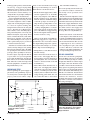
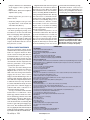
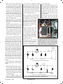
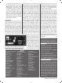
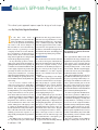
Adcom’s GFP-565 Preamplifier, Part 1 This author’s purist approach improves upon the design of a classic preamp. By Gary Galo, Regular Contributor n the Feb. 1990 issue of Stereophile, I reviewed Adcom’s then new GFP-565 preamplifier, one of the products issued during the tenure of C. Victor Campos as Adcom’s Director of Product Development (clearly a “golden-age” for the company; in 1995 he became Adcom’s Vice President for Product Development).1 Under Victor’s direction, Walt Jung was brought into the design team for this IC op-amp-based preamp. In my extremely positive review, I made some rather bold statements regarding modifications to the preamp. In a nutshell, I noted that the GFP-565 was a thoroughly engineered product that probably wouldn’t benefit from the usual parts substitutions. I actually warned potential tweakers of the possibility of making the preamp worse, unless modifiers knew exactly what they were doing. It is no secret to readers of aX as well as its predecessors, Audio Electronics, Audio Amateur, and Speaker Builder that I began tweaking my 565 preamp within a year of the publication of my review. Indeed, over the years I have made numerous references to my “extensively modified” Adcom GFP-565 in these pages. Many readers of these magazines have asked for details on these modifications. Some have even asked, “What gives? I thought you said it couldn’t be modified!” Have I contradicted myself? Not really. I still believe that, at the time I wrote the review, substituting your favorite capacitor or op amp would probably have degraded the preamp. The GFP-565 was an excellent product, especially for the price, when it was I 6 audioXpress 11/03 introduced. But, my goal has been to raise the level of performance to something well beyond that of a “best under$1000 commercial preamp.” The GFP565 first appeared in the fall of 1989 14 years have now passed since its introduction, and much has happened in the interim. An article describing possible upgrades is probably long overdue. MODIFICATIONS The modifications I’ll describe amount to far more than parts substitutions. They involve wholesale replacement of most of the original circuitry, to the point where the modified preamp is really an entirely new design in the Adcom GFA-565 case. The original Adcom case and PC board are quite versatile. With some ingenuity you can change most of the circuitry, yet still retain the attractive and functional case design. The new preamp is a “purist” design, eliminating the tone controls, high filter, loudness contour, processor loop, and headphone amplifier. If you find these functions necessary, this may not be the right preamp for you. I have divided the project into three parts. Parts 1 and 2 will involve complete replacement of the power supply, adapting Walt Jung’s “Improved Positive/Negative Regulator” specifically for this project.2 This regulator is a substantially improved version of the one described in the 1995 series “Regulators for High-Performance Audio,” Parts 1 through 4.3 Part 3 of the 565 mod will cover the new line stage, and Part 4 will describe a new phono preamplifier with DC-servo control. I spent some time wrestling with the www.audioXpress.com PHOTO 1: Delay-circuit mod components D916 and R922 are soldered to the bottom of the Adcom PC board. order of presentation. Much of the new circuitry in the line stage and phono preamplifier was developed after my initial replacement of the original Adcom power supply. I had no idea how the new circuitry would perform or if it would even be stable with the original supply. For this reason alone, the power-supply modifications must come first. The power-supply mods are also the most difficult and tedious part of the entire project, perhaps sufficiently so to discourage some builders. I believe it is better to put the hardest part out of the way first, rather than lead readers through three parts of the project only to have them find that the final installment is more than they had bargained for. In order to begin these modifications, you’ll need to purchase a GFP-565 service manual, which is mandatory; I don’t recommend attempting to modify this preamp without consulting it. You’ll need to refer to the original schematic and PC board layout many times during the course of these mods. You can purchase the GFP-565 service manual from Adcom’s parts department (see Sources for their e-mail address). If you have difficulty obtaining a service manual, e-mail me at [email protected]. Of course, you’ll also need a GFP-565 preamp to modify. The 565 was an ex- tremely popular product, and used units do turn up. I suggest trying Ebay (www.ebay.com) for starters, as well as Adcom dealers (you’ll find a list of Adcom dealers on their website). I recently saw two 565 preamps on Ebay for “Buy it Now” prices of less than $300. A thorough familiarity with the Jung regulator design is necessary for the successful completion of Part 1. Walt’s “Improved Positive/Negative Regulator” article is required reading. The background described in the four-part series, “Regulators for High-Performance Audio,” is also extremely important, particularly Parts 3 and 4 by Jan Didden and myself, respectively. Back issues of Audio Electronics and Audio Amateur are available on the aX website, www.audioXpress.com. If you intend to pursue this project, you’ll need to order the back issues now. Adcom does not endorse these modifications, and any changes to the preamp will void your warranty. Since the GFP565 preamp was discontinued several years ago, this is probably not an issue, but don’t expect any help from Adcom or your dealer once you’ve begun this project. The modifications described in these articles are for advanced builders with sufficient technical background and test equipment to troubleshoot and fix problems if they occur. PRELIMINARY STEPS Before beginning the power-supply replacement, some preliminary steps are necessary. Here and throughout this project, you’ll need to remove compo- nents on the Adcom PC board. I suggest a good desoldering tool, such as Radio Shack’s cost-effective 64-2060. • Check the main supply rails to make sure the regulators are at –17.5V DC. Some early samples of the GFP-565 had the regulators set at –19V, higher than the absolute maximum ratings of the IC op amps used in the preamp. In these preamps R908 is 15k. The rail voltages can be lowered to –17.5V by changing R908 to 12.7k, the value used in most production samples of the GFP-565. I suggest doing this even though the main regulators won’t be used for too long. Early on in my work on the GFP-565, Walt Jung suggested a couple of improvements to the circuit that controls the output muting relays. I also opted to increase the turn-on delay to 20 seconds. Refer to Fig. 1 for the following steps: • Change R920 to 332k. This increases the turn-on delay. • Add a 1M resistor from the base of Q908 to the -15V supply. This is to drain leakage from the Darlington pair Q908/Q909. You can solder this resistor to the bottom side of the PC board (Photo 1). • Add a 1N4002 diode from the base of Q907 to the -15V supply. The cathode of the diode connects to Q907 and the anode to -15V. This protects the emitter/base junction of Q907 from reverse voltage during power-down. You can also solder this diode to the bottom +15V "A" +10V R921 332 D906 1N4148 "B" -14V Q909 Q908 2SC945 • Remove J51 and J52 on the main PC board. Replace these with two short lengths of 16AWG insulated solid bus wire soldered to the bottom side of the board. Bend the bus wire to form a right-angled “U.” You could leave the old jumpers in place, but it will be more difficult to solder the new jumpers to the PC board with the old ones protruding through the board. NEW RCA CONNECTORS Adcom used cost-effective gold-plated, PC-mount RCA connectors on the GFP565. The modified preamp is refined enough that differences between input and output connectors should be readily audible. Adcom followed normal industry practice by putting left-channel jacks on the top row and right-channel jacks on the bottom. Unfortunately, it is difficult to fit insulated, chassis-mount jacks in the bottom holes the PC board obstructs the insulators, and the mounting nuts and/or ground washers may make accidental contact with the PC board ground plane. Q907 2SC945 -15V D905 + **R922 1Meg FIGURE 1: The modified delay circuit for the muting relays, showing the addition of R922 and D916. 8 audioXpress 11/03 Turn on the preamp and check the voltage at the base of Q907: it should be -15V. Verify correct operation of the muting relays. Adcom lowered the impedance of the power-supply buses by paralleling them with brass rails on the component side of the PC board. But, they left two weak links in the supply distribution chain: jumpers J51 and J52, which are 22AWG wire. This is where the supply rails branch off the main buses to power the line stage. Here’s an easy fix (Photo 2): *R920 332k RD9.1E Q909 2SC945 side of the PC board (Photo 1). C921 100uF R919 49.9 **D916 1N4002 R914 10k -15V * = New Value ** = New Part From D902/ C913/R913 A-2289-1 www.audioXpress.com PHOTO 2: New 16AWG jumpers for the main power-supply buses. These jumpers replace a weak link in Adcom’s powersupply distribution. Fortunately, my purist approach to this project allows the removal of some unnecessary connectors, specifically the processor loop inputs and outputs, along with the normal and lab outputs. This will allow space for replacement of the critical RCA connectors: the CD and phono inputs, plus the bypass outputs. There are many excellent chassismount RCA jacks available with gold plating and Teflon insulation. I’ve listed a few in the Parts List. One of the bestkept secrets in high-end audio construction is the jacks sold by MCM Electronics for only $1.69 each. These are outside-mount, so the nut goes on the inside, which is a bit inconvenient. It’s also a little tricky to grip the outside of the connector with pliers to prevent turning while you tighten the nut. But, if installed properly, their performance will belie the cost, and the insulating washers fit the ³⁄₈†Adcom holes. I suggest applying Caig Pro-Gold GP5S-6 contact conditioner to the ground washer and nut before installation to ensure a good long-term connection (do this with any connector that has a separate ground washer). I use the Connex 53451 house-brand connectors sold by the Parts Connexion in my own preamps. These are insidemount, outside-nut, so they are easy to install. The insulating washers require a ¹⁄₂†hole, so you must enlarge the Adcom holes. The Vampire M2F is similar to the Connex, and also requires a ¹⁄₂†hole. I suggest a Greenlee ¹⁄₂†type 730 round knockout chassis punch (Mouser #5863801) for this purpose. Let’s start by replacing the output jacks. • Remove the rear panel, which allows access to the rear panel jacks. You’ll need to remove all of the jack assembly mounting screws in order to loosen the rear panel. • Remove the processor loop input and output jack assembly. Unsolder the four signal and two ground leads from the PC board and remove the block. • Remove the output jack assembly, which consists of six RCA connectors in one block. Unsolder the six signal and three ground leads and remove the block. • Remove the phono and CD input jack assembly. Unsolder the four signal and two ground leads from the PC board and remove the block. The rear corner of the PC board is now hanging loose, so retain one pair of jacks from the output assembly to provide proper support (Photo 3). • With a band saw or coping saw, separate the left-most pair of connectors (looking at the back of the jack assembly) from the rest, carefully cutting around the mounting screw hole so it is retained. This is the “norm” out jack pair. If you do this right, you’ll still have plenty of plastic around the mounting screw hole, while providing adequate clearance for the new RCA jack insulators. You might want to do a “dry fit” before soldering everything in place. Re-solder the jack-assembly connections to the bottom of the PC board. Then, reinstall the rear panel, including all of the mounting screws for the remaining chassis-mount jacks. The “norm” out jack assembly has no electrical function in the new preamp its only purpose is to provide proper support for the corner of the PC board. • Mount the new RCA output connectors in the holes previously occupied by the left lab and bypass connectors, enlarging the holes if necessary. The ground washer tabs should face the PC board. The connector in the lab hole will be the right channel, so put PHOTO 3: New RCA output connectors. The pair on the right are an optional set of aux outputs that may be useful for biamping. The “norm” output jack block, cut away from the original three-pair assembly, has no electrical function, but it supports the corner of the PC board. 10 audioXpress 11/03 a red-banded connector here if yours are color-coded. • Solder bare hook-up wire from the ground washers to the ground holes in the PC board. I suggest using stripped D.H. Labs OFH-20 hookup wire, or a stripped conductor from their BL-1 interconnect cable. • Solder insulated hook-up wire from the center pins of the new jacks to the left and right bypass out holes in the PC board. Again, I suggest D.H. OFH-20 Labs hookup wire, or the center conductors from their BL-1 interconnect cable. The old lab out holes in the PC board are no longer used. In Part 3, covering the new line-stage circuitry, I’ll offer the option of adding a pair of auxiliary output jacks, electrically identical to the main outputs, for passive biamping such as I described in Speaker Builder 2/92.4 Active biamping may also benefit from the auxiliary outputs. If you are building your own active crossover, you can probably eliminate the input buffer and drive the high- and low-pass sections directly from the preamplifier’s main and aux outputs. If you need the aux outputs: • Mount another pair of RCA connectors in the holes previously occupied by the left processor out and in jacks. These will be the right and left outputs, respectively. • Solder bare hookup wire from the ground washers to the ground holes on the PC board. • Solder insulated hookup wire from the center pins of the new jacks to the left and right processor out holes on the PC board. These jacks will not be functional until Part 3 is completed. Photo 3 shows the new output connectors installed in the 565 preamp chassis and wired to the PC board. PHOTO 4: New CD input jacks are shown on the left, along with new phono jacks on the right. The twisted-pair leads to the left phono input jack are soldered to the bottom of the PC board. www.audioXpress.com I painted over the unneeded labeling on the rear panel with black semi-gloss modeling enamel, and made computerEXTERNAL POWER SUPPLY BOX F1 1.5A • Remove the original grounding screw. Adcom put a dab of solder on 12 audioXpress 11/03 SIGNAL-PATH PURIFICATION Although I don’t describe the new linestage circuitry until Part 3, there are some preliminary steps that you should take at this point to simplify the signal path and remove active devices that will no longer be used. First, disconnect the Loudness Contour circuit (Photo 6). T1 VPS36-2200 18+18V AC L1 22mH 6 12 5 11 2 8 1 7 20VAC P1 Neutrik NAC3FCA 120V AC IN C1 0.47uF/250VAC 20VAC C2 0.47uF/250VAC Ext Supply Chassis GND ADCOM 565 CHASSIS and PC BOARD D907-D910* HFA08TB60 20VAC AC1 J1** Neutrik NAC3MPA +26VDC To + Reg L001** 56mH - E1 C906* 4700uF C908* 1uF C905* 4700uF C907* 1uF + PC GND **R905 8.25k AC2 20VAC To - Reg -26VDC PC Board GND L1 D001 LTL2201A C901-C904* 0.47uF/100V R901-R904** 47.5 1/2W D902 1N4003 R913 3.32k To R914 + Photo 4 shows the new phono and CD input jacks mounted on the 565 preamp chassis and wired to the PC board. I also suggest replacing the original ground post with hardware that’s electrically more secure and a bit easier to get your fingers around, such as a 6-32 machine screw with a knurled-head thumb nut. These are normally hardware-store items, but I’ve also included Digi-Key part numbers in the Parts List. Minimum order quantities are 100 unless you need to stock up, you may choose to obtain them locally. printed labels for the new input and output jacks using Avery 8160 labels cut to size (avoid Avery’s new “SmudgeFree” labels they have poor print quality on ink-jet printers). I also covered the labels with Scotch Magic Tape. Photo 5 shows the rear panel with the new connectors and ground post. I suggest then applying Caig ProGold GP5S-6 contact conditioner to the newly installed jacks. I find that it is less messy to apply the ProGold to the RCA plugs on your interconnect cables, shake off the excess, and then insert the plugs into the jacks once or twice. D.H. Labs’ new Silver Sonic Ultimate RCA Connector is an excellent mate to the RCA jacks I’ve recommended. + • Install the new CD input jacks in the holes previously occupied by the left CD and left phono jacks. Enlarge the holes with a punch, if needed. • Solder bare hookup wire between the ground washers, and solder a single piece of insulated hookup wire from the bare wire to the CD ground hole on the PC board. • Solder insulated hookup wires between the center pins of the new CD jacks to the CD input holes on the PC board. • Punch two new holes for the new phono input jacks. If you are using the MCM jacks, Greenlee doesn’t make a ³⁄₈†punch. I suggest Sescom’s PUNCH1. You can locate these holes in the same plane as the new CD input jacks, between the ground post and the edge of the chassis. • Mount the new connectors in the newly prepared mounting holes. • Use a short length of twisted-pair hookup wire to connect the right phono input jack to the PC board through the top side of the board. Twist together D.H. Labs OFC-20 hookup wire, conductors from their BL-1 interconnect, or use their T-20X unshielded twisted-pair hookup wire. Use another short length of twistedpair hookup wire to connect the left phono input jack to bottom side of the PC board. Note that each new phono input jack has its own ground wire; both ground wires connect to the same PC board ground hole. the end of the screw so it wouldn’t accidentally come out. Hold your soldering iron against the end of the screw while removing the screw with a screwdriver. • A 6-32 machine screw should fit the existing hole without enlargement. If necessary, enlarge the hole slightly; the protrusion on the inside of the chassis will remain. • Scrape the paint off the end of the protrusion to ensure a good connection, and mount a 6-32 ·⁵⁄₈†machine screw from the inside of the chassis using a hex nut and lock washers. Use two lock washers one for the screw head inside the chassis and another for the nut on the outside of the chassis. You can then tighten the nut with a nut driver without the screw turning (there’s no room to get a screwdriver inside the chassis to hold it). Put the knurled nut on the machine screw. + Now install the new CD and phono input jacks (Photo 4). C913 22uF/50V E2 * = New Value ** = New Part (* and ** refer to parts in the preamp chassis only. All parts in the external supply are assumed to be new.) FIGURE 2: Top schematic is the external power supply. Bottom schematic shows internal changes to the GFP-565 preamplifier that will be described in Part 2, including the new rectifier bridge, R/C snubbers, a DC common-mode choke, and new rawDC filter capacitors. A-2289-2 www.audioXpress.com • Cut a ¹⁄₄†gap in the PC trace closest to the front edge of the PC board, directly in front of and perpendicular to J49, next to the volume control VR204. Everyone has his or her own method for cutting PC traces. I use a combination of single-edge razor blades and X-Acto knives (be careful!). You can also use a Dremel tool with a small grinder attachment, but I suggest holding a vacuum cleaner nozzle close to the area you’re grinding so that the fine debris is removed without making a mess. Either way, be sure that the PC board is completely clean when you are finished. • Remove jumper J49 near the volume PHOTO 5: The rear panel with new input and output connectors and a new ground post. PHOTO 6: The loudness-contour circuit is disconnected by cutting one trace and removing jumper J49. control VR204. Next, remove the tone-control circuits and headphone amplifier from the signal path: • Remove jumpers J124 and J27. These are the signal connections to the tone-control circuits, high filter, and the headphone amplifier. • Remove IC205 and IC206. These are the tone-control op amps. • Remove jumpers J7 and J9. These connect the main-supply rails to the tone-control circuits. On some samples of the GFP-565 I observed a very small local supply oscillation at IC205/206 due to the lack of any local supply bypassing. Removing these PHOTO 7: Two jumpers are soldered to the PC board to bypass the processor loop switch contacts. HiFi Digital Amplification, that simply works, and sounds... GREAT! ZAPpulse 2.0 Audio Power Amplifier using New advanced Technology to produce 400 Watt RMS (4 Ohms) on a Credit Card size Footprint ! Efficiency ~ 96% = environment friendly TEFLON/SilverWire SIMPLE! +60V 10.000uF 63V 10.000uF 63V Power GND -60V EMC Optimized 4 layerPCB -Out +Out Available as a ready to play audio appliance, or modules for DIY projects. Almost no heat sinking is called for, a thin steel sheet metal floor of the enclosure will do! Build as mono blocks, stereo, 5 ch, 7 ch in one enclosure. 200 W/8 400W/4 650W/2 RMS cont. pwr. 5 - 150.000 Hz +/- 3dB THD 0.02%@10W Damping Factor 130 Max. Current 62 Amp. -Out 1 2 3 Special Edition Black Gate VK 19 Watts Total Loss 500 Watts RMS Sound! Predator SE 250 Watts RMS in 8 Ohms Stereo Power Amplifier DIY Modules SE Version w/Black Gate VK as shown: +Out Predator SE 2 x 250 Watts RMS USA: DIYCABLE 153 Mountain Home Road Port Angeles WA98362 Washington tel 360-452-9373 www.diycable.com Great Britain: Audio Atmosphere 29 Drake Avenue Penkridge Stafford ST19 5UA tel 0 1785 711232 www.audioatmosphere.com Australia: Soundlabs Group pty. POBox 307 Surry Hills NSW 2010 tel 02 9660 1228 www.soundlabsgroup.com Scandinavia: L C Audio Technology Christiansgade 1 DK7500 Holstebro tel +45 97410863 www.lcaudio.com audioXpress November 2003 13 jumpers eliminates the distribution of the supply to these op-amp footprints. • Remove IC301. This is the headphone amplifier dual op amp. Finally, bypass the processor loop switch contacts: • Solder two jumpers to the processor loop switch S205, on the bottom side of the PC board (Photo 7). Always leave the processor loop switch “out” when operating the preamp, so unused PC traces for the send and return lines aren’t hanging off the signal path. This completes the preliminary steps. Check the preamp to make sure it is operating correctly via the bypass outputs. Remember that the turn-on delay is now 20 seconds. EXTERNAL POWER TRANSFORMER The new power-supply scheme houses an AC line filter and a new power transformer in a separate metal box. There are two reasons for doing this. First, the 80VA transformer I use is too large to fit inside the Adcom chassis. Second, the hum field radiated by the unshielded transformer would compromise the low-noise performance of the preamp, especially the phono section. I have not used exotic wiring for the power-supply construction in this preamplifier. You are free to do so, if you wish. I have also developed an alternate supply that houses dual rectifier bridges and raw DC filtering in the external box. The alternate supply is a bit more difficult to implement, but if there is sufficient interest, I may describe it in a future installment. Nearly all of the parts used in the external supply described in this article could also be reused in the alternate supply. See Fig. 2 and Photo 8. The Parallax transformer I recommend is a dualbobbin type, which is much more effective in attenuating power-line noise than toroidal types, even those with electrostatic shielding. Rick Miller supplied some measurements documenting this for Part 4 of the 1995 power-supply regulator series.5 The Parallax transformer is also very tightly wound, with virtually inaudible mechanical buzzing, and is readily available from Mouser and Newark. 14 audioXpress 11/03 MagneTek divested itself of its power transformer line some time back; Parallax is the successor. There are equivalent transformers from other manufacturers, including Hammond Manufacturing and Signal Transformer. The Signal A-41-series I recommended in the 4/1995 article is still available, but they now have a $15 handling charge on orders less than $100, which I consider unreasonable. I have also observed a higher level of mechanical buzzing from the Signal A-41 transformers, compared to the Parallax. Some builders may wish to use an even heftier transformer. The next size up in the Parallax series is 130VA, but the higher secondary voltages under the load encountered in this preamp will increase the heat dissipation of the regulators, which may necessitate additional heatsinking. I have not tried a 130VA transformer with this preamp. Neutrik PowerCon connectors are used to connect the transformer secondary to the preamplifier. An AC linecord that plugs into a switched outlet on PHOTO 8: The external power supply. This supply houses an 80VA dual-bobbin power transformer and AC power line filter. A Neutrik PowerCon connector is used to connect the transformer secondary to the preamp. PARTS LIST PRELIMINARIES (1) Adcom GFP-565 Service Manual (Adcom) Adcom Regulator Voltage Change (1) 12.7k, ¼W resistor (R908), Digi-Key 12.7KXBK-ND Muting Circuit (1) 1N4002 diode (D916), Digi Key 1N4002DICT-ND (1) 1M, ¼W 1% metal-film resistor (R922), Digi-Key 1.00MXBK-ND (1) 332k, ¼W 1% metal-film resistor (R920), Digi-Key 332KXBK-ND New Input and Output Jacks (6) or (8) Gold-Plated, Teflon-Insulated, Chassis-Mount RCA Jacks: MCM 50-2110 (Black Marking) and 50-2105 (Red Marking) (MCM Electronics) or CONNEX-53451 Inside-Mount (sold in L/R pairs; Parts Connexion) or Vampire M2F (sold in L/R pairs; Welborne Labs) New Ground Terminal (1) 6-32 ·⁵⁄₈†machine screw, Digi-Key H364-ND (2) #6 Lock washers, Digi-Key H240-ND (1) #6 Hex nut, Digi-Key H220-ND (1) #6 Knurled head thumb nut, Local Hardware Store Miscellaneous Hookup wire: D.H. Labs OFH-20, T-20X twisted pair, or center conductors from BL-1 (D.H. Labs & Welborne Labs or Welborne Labs TWR, TWB or TWW (Welborne Labs); 16 AWG insulated solid bus wire, Digi-Key A3057B-100-ND Caig ProGold GP5S-6 contact cleaner, MCM Electronics 200-190 or Caig Laboratories GP5S-6 Black semi-gloss modeling enamel Avery 8164 or equivalent computer labels (NOT Avery “Smudge-Free”) EXTERNAL POWER SUPPLY External Supply Parts: (1) Bud Aluminum Minibox, 6 ·5 ·4†, Mouser 563-CU-3007A (or Sescom MC-8A) (2) Panasonic ECQ-UV, 0.47µF, 250V AC, Digi-Key P4614-ND (C1, C2) (1) Panasonic H-series Line Filter, 22mH, 1A, Digi-Key PLK1034-ND or Panasonic V-series Line Filter, 56mH, 1.1A, Digi-Key PLK1017-ND (L1) (1) Parallax (Formerly MagneTek) VPS36-2200, 18+18 VAC/80VA, Mouser 553-VPS362200 (T1) (1) Neutrik Powercon NAC-3FCA, Mouser 568-NAC3FCA (P1) (1) 1.5A Fast-Blow Fuse, Radio Shack 270-1006 (F1) (1) Panel-mount fuse-holder, Digi-Key 283-2344-ND, Radio Shack 270-367 Miscellaneous 16AWG, 2-cond. AC power cord and plug Strain relief for above 3-cond. 14AWG SJT wire Strain relief for above 3-cond. 16AWG SJT wire 16 AWG insulated solid bus wire, Digi-Key A3057B-100-ND Prototyping board, Circuit Specialists IF-RFB Plexiglass Preamp Chassis/PCB Parts: (1) Neutrik Powercon NAC3MPA, Mouser 568-NAC3MPA (J1) (1) 2.0A Slow-Blow Fuse, Radio Shack 270-1024 (F001) www.audioXpress.com the preamp provides 120V AC to the line filter and transformer. Fig. 2 and Photo 8 show the outboard supply schematic and give an idea of how to assemble it in the new external box. I won’t give stepby-step assembly procedure for the external box, because it should be self-explanatory. However, here are a few suggestions for assembly: • I used a Bud 6 · 5 · 4† aluminum minibox for the outboard chassis. After drilling and punching the necessary holes in the box, spray-paint it with black, semi-gloss, fast-dry enamel. Sescom’s MC-series of metal cabinets is available in a black-anodized finish, and offers an alternative to the Bud box. The bottom plate of the modular Sescom boxes may need mounting reinforcement in the center, to support the weight of the power transformer. • Mount the AC line-filter components C1, C2 and L1 on a small piece of RF prototyping board from Circuit Specialists (Photo 9). The sturdy solder pads on this board facilitate mechanically secure mounting of the components. One 10 ·10†piece is enough for this entire project. Although the cost is rather high about $55 the durability and ease of use is well worth the expense. As of this writing, Circuit Specialists is still giving away a $29 DMM free with any purchase over $50 an added incentive. • Put a piece of insulating Plexiglas between the prototyping board and the metal box. You must make the Plexiglas larger than the prototyping board, so it extends beyond the board by ½†on the ends where AC connections are made. This ensures that 120V AC won’t accidentally make contact with the chassis. Use two 4-40 · ³⁄₈† machine screws, lock washers, and nuts to mount the board and Plexiglass to the metal chassis. • Use 16AWG insulated solid bus-wire to parallel the transformer primaries (Fig. 2). You can use the same type of wire to connect the secondary windings in series. • Use a length of 3-cond. 14AWG SJT wire for the secondary connection, with an appropriate strain relief. The wire should be available from any electrical-supply house. I used a hard- ware-store strain relief designed for not to solder, treat the wiring with AC electrical-box use. Caig ProGold before connecting it to • The line cord should be 2-cond., the PowerCon. 16AWG. Again, use an appropriate • After assembling the supply, check strain relief. the secondary voltages at the Neutrik • The line cord and transformer secPowerCon connector. It’s easier to do ondary cable can be up to 6¢ long, althis before putting the connector tolowing you to place the external supgether. With no load you should meaply away from the preamp. If you can sure ~21.5V AC either side of ground. place the outboard supply close to the preamp, shortening these cables CONNECTION TO CHASSIS Now that the outboard supply is built, may provide a minor sonic benefit. • Note the labeling of the Neutrik it’s time to prepare the preamp chassis NAC3FCA PowerCon connector, par- for the connection of the external supticularly the ground pin. Connect the ply. PowerCon to the end of the SJT cable. You can use the screw-terminal connections provided by Neutrik, or remove the screws and hardware, and solder the wires to the connector (I prefer soldering). The plastic used by Neutrik seems to have a very high melting point you can apply PHOTO 9: The AC line-filter assembly for the external supply is shown on the left. The raw- DC common-mode considerable heat when choke (assembled and installed in Part 2) is shown on soldering without deform- the right. Components are soldered to Circuit Specialists ing the plastic. If you opt RF Prototyping Board. 7KHVRXUFHIRUSUHPLXPHOHFWURQLFWHVWLQJHTXLSPHQW 1HZ3UH2ZQHG 2VFLOORVFRSHV 3RZHU6XSSOLHV 6SHFWUXP$QDO\]HUV 6LJQDO*HQHUDWRUV 'LJLWDO0XOWLPHWHUV 1HWZRUN$QDO\]HUV )XQFWLRQ*HQHUDWRUV ,PSHGDQFH$QDO\]HUV )UHTXHQF\&RXQWHUV $XGLR$QDO\]HUV &DOOQRZWRVSHDNWRRQHRIRXU NQRZOHGJDEOHVDOHVSHRSOHRU EURZVHRXUH[WHQVLYHRQOLQHFDWDORJ ZZZWHVWHTXLSPHQWGHSRWFRP 6DOHV5HSDLU&DOLEUDWLRQ5HQWDO/HDVHV%X\6XUSOXV audioXpress November 2003 15 • Clip the power leads at AC5 and AC6 on the Adcom TX 919115 voltageselect PC board, as close as possible to the board. Remove the white lead it goes to one of the switched outlet’s neutral contacts. Strip and tin the hanging end of the brown wire from the fuse holder. You will use it shortly. • Remove the three wire-wrap posts at E1, AC1, and AC2 on the main PC board. These are the power-transformer secondary leads. • Cut two cable ties to free the Adcom TT-271-GF power transformer leads. Take care to cut only the ties, and not the leads. • Remove the power transformer, along with the voltage-select PC board and its mounting bracket. Save the power transformer mounting hardware. Also remove and save the metal-oxide varistor MOV001 from the voltageselect PC board. You can discard the transformer and voltage-select board, or save them for another project. Now you can re-configure the innermost switched outlet so that it is both switched and fused (Fig. 3). This is the outlet directly above the fuse holder. The AC power cord from the outboard supply will be plugged into this outlet so that the preamp’s front-panel power switch will still function normally. Fusing the outlet is an added safety precaution if there is a fault in the external supply’s line cord, this fuse will blow. The main power-supply fuse is F1 in the external chassis. F1 is now 1.5A, rather than the 1A used in the original Adcom design, which allows for the additional surge currents required to charge higher-value power-supply bypass capacitors when you power up the preamp. Fig. 3A shows the original Adcom wiring configuration for the switched outlets. • Re-wire the switched outlet closest to the main PCB (as shown in Fig. 3B). You can connect the tinned, hanging wire from the fuse holder to the hot terminal (the top pin) of the switched and fused outlet. Replace F001 with a 2.0A slow-blow fuse. • Re-connect MOV001 between the fuse-holder and the bottom pin of the re-wired switched and fused outlet. 16 audioXpress 11/03 You will need to lengthen the MOV leads and cover them with sleeving. The fuse holder output connects to the brown wire that previously went to the voltage selector board. The bottom pin of the re-wired outlet is the wider of the two pins, and should have a white wire attached. Photo 10 shows the re-wired switched outlet and fuse holder. Photo 11 shows new labeling for the re-configured outlet and the fuse holder, and also how to mount the Neutrik NAC3MPA PowerCon chassis connector on the rear panel between the line cord strain relief and the fuse holder. • Using a single-edge razor blade, carefully remove the adhesive serial number, located between the fuse holder and the line-cord strain relief. Using Scotch Magic Tape, re-fasten the serial number to the left of the fuse holder (Photo 11). • Punch a ¹⁵⁄₁₆† hole for the PowerCon chassis connector in the location shown in Photo 11 . A Greenlee ¹⁵⁄₁₆† punch is available from Mouser (#586-3808). • Center the PowerCon chassis connector in the hole, orienting it so the “Neutrik” label is on the bottom. Mark and drill a pair of holes to accommodate #4 machine screws. Mount the connector with ³⁄₈†, 4-40, flat-head machine screws, lock washers, and nuts. • Connect the three pins of the PowerCon chassis connector to holes AC1, AC2, and E1 on the PC board (Photo PHOTO 10: The re-wired switched—and fused—AC outlet is shown top center. Also shown is the wiring from the Neutrik PowerCon connector to the main PC board, and the DC common-mode choke assembly (installed in Part 2) mounted with a pair of brass brackets. Note the rubber insulator fastened to the bottom of the fuse holder with a nylon cable tie (also installed in Part 2). C002 0.0047uF F001 1.0A TX919115 VOLTAGE SELECTOR PC BOARD AC6 S001 Power 120V AC IN AC5 UNSWITCHED SWITCHED A. ORIGINAL ADCOM OUTLET AND FUSE ARRANGEMENT C002 0.0047uF F001 2.0A SLOW BLOW S001 Power MOV001 120V AC IN UNSWITCHED SWITCHED Z SWITCHED AND FUSED B. MODIFIED OUTLET AND FUSE ARRANGEMENT FIGURE 3: The original Adcom convenience outlet wiring is shown in schematic “A.” A-2289-3 Schematic “B” shows the re-wired switched and fused outlet. www.audioXpress.com 10). Note that E1 is ground; the polarity of the two hot leads connected to AC1 and AC2 isn’t critical. I used 16AWG SJT wire taken from a power cord, twisted together as shown in the photo. 14AWG wire will be difficult to fit in the PC board holes the length is so short that I find 16AWG to be fine. Leave enough slack in the wiring to allow room for the DC filter choke shown in the photo (the choke will be installed in Part 2). board transformer into the fused and switched outlet on the preamp, and plug the preamp’s line cord into an AC outlet. Turn on the preamp power switch and check the transformer secondary voltages at AC1 and AC2 on the main PC board, referenced to E1. There should be ~20VAC at AC1 and AC2. Remember that this is an 80VA transformer, so the secondary voltages will be a bit higher than the specified 18V AC under the load encountered in this preamp. Check the regulated supply CHECKPOINTS voltages, which should read –17.5V DC. At this point, the preamp should operate It is normally a good idea to orient the properly with the new outboard trans- AC line cord for minimum leakage to former. Treat the PowerCon contacts the chassis. The optimum position is with Caig Pro-Gold and connect the that which yields the lowest AC potenPowerCon plug on the outboard supply tial between the preamp chassis and the cable into the PowerCon connector on AC power line ground. You can check the preamp chassis (Pro Gold is suitable your preamp by temporarily adding a for most precious metals, including the non-polarized ground lifter to the line nickel plating on the PowerCon). Align cord from the external supply. This will the connector, insert and twist until it allow you to reverse the cord in a polarclicks. Plug the line cord from the out- ized outlet. Using an AC voltmeter, measure the potential between the preamp chassis and the AC line ground with the AC cord in its normal orientation; reverse the AC cord orientation and measure again. If the reverse position gives a substantially lower PHOTO 11: Rear-panel view showing the Neutrik Power- reading (more than a few volts), you should reverse the AC line Con connector. The serial number has been moved to cord polarity inside the external the left of the fuse holder, and new labeling has been added for the fuse holder and the fused AC outlet. SOURCES Adcom, division of Klein Technology Group, LLC 8551 E. Anderson Drive Suite 105 Scottsdale, AZ 85255 480-607-2277 FAX 480-348-9876 www.adcom.com [email protected] Accutek Microcircuit Corp. 2 New Pasture Rd., Ste. 1 Newburyport, MA 01950 978-465-6200 FAX 978-462-3396 www.accutekmicro.com [email protected] Analog Devices (factory-direct on-line ordering) www.analog.com Caig Laboratories, Inc. 12200 Thatcher Court Poway, CA 92064 858-486-8388 FAX 858-486-8398 [email protected] www.caig.com Circuit Specialists Inc. 220 South Country Club Drive #2 Mesa, AZ 85210 1-800-528-1417 480-464-2485 www.web-tronics.com D.H. Labs, Inc. 612 N. Orange Ave., Suite A-2 Jupiter, FL 33458 561-745-6406 www.silversonic.com Digi-Key Corp. 701 Brooks Ave. South Thief River Falls, MN 56701-0677 1-800-344-4539 www.digi-key.com Mouser Electronics 1000 N. Main St. Mansfield, TX 76063-1511 1-800-346-6873 www.mouser.com Newark Electronics 1-800-463-9275 (Call for the nearest sales office) www.newark.com Parts Connexion 2885 Sherwood Heights Drive Unit# 72 Oakville, Ontario CANADA L6J 7H1 1-866-681-9602 (Toll-free order line) www.partsconnexion.com Radio Shack www.radioshack.com Sescom, Inc. 707 N. Lindenwood Olathe, KS 66062 USA 1-800-634-3457 www.sescom.com Welborne Labs P.O. Box 260198 971 E. Garden Drive Littleton, CO 80126 USA 303-470-6585 www.welbornelabs.com supply. The easiest place to do this is at the input to the line filter. In the preamps I’ve modified, I’ve found little difference (only a volt or so) changing AC polarity. It’s worth checking, though. Next time, we’ll replace the rectifiers, snubbers and filter capacitors, and add common-mode filtering to the raw DC supply. We’ll also remove the Adcom supply regulators and install the Jung Improved Regulators (note that Fig. 2 contains parts that will be installed in Part 2). In the meantime, listen to the preamp and enjoy the improvement a high-current transformer can make. If you use a power-line filter with sequenced switching, such as those made by Adcom or Panamax, you can plug the outboard supply’s line cord directly into the power-line filter. In this case, the preamp’s power cord is not used. You can also do some critical listening to see whether you can hear a difference when the preamp power cord is eliminated (this may make a greater difference when the rest of this project is completed). ❖ All photos were taken by the author using a Nikon CoolPix 950 digital camera. Photo editing was done using Microsoft Photo Editor V. 3.0 and Paint Shop Pro V. 7.04. Schematic drawing was done using CircuitMaker 2000 Professional Edition with Service Pack 1. REFERENCES 1. Galo, Gary A., “Adcom GFP-565 Preamplifier” in Stereophile, Feb. 1990, pp. 150-158. 2. Jung, Walt, “Improved Positive/Negative Regulators” in Audio Electronics, 4/2000, pp. 8-19. 3. Jung, Walt, Jan Didden, and Gary Galo, “Regulators for High-Performance Audio,” Parts 1–4 in Audio Amateur, 1, 2, 3, and 4/1995. 4. Galo, Gary, “Bi-Amping the Sapphire II/Sub I System” in Speaker Builder, 3/1992, pp. 24-32. 5. Galo, Gary, “Regulators for High-Performance Audio, Part 4: Real-World Implementations and Sonic Evaluations” in Audio Amateur 4/1995 (including power-transformer measurements by Rick Miller on p. 36). ACKNOWLEDGMENTS Special thanks go to Walt Jung, not only for the design of the Improved Regulators, but for the many suggestions and insights he has shared since I began modifying the preamp over a decade ago. Thanks also to my wife Ellen for her proofreading, to Rick Miller for his input on rectifier diodes and snubbers, and to Rich Markell of Linear Technology for supplying IC regulator samples at a time when dealer’s stocks were in short supply. Last, but not least, I would like to thank Victor Campos for his interest and encouragement over the many years I have been working on this preamp, for the meticulous proofreading on which I have relied countless times, and for badgering me to finally get this article finished. Victor’s loan of one of the three preamps I have modified was extremely valuable in helping me develop a coherent (I hope!) assembly procedure for these articles. audioXpress November 2003 17