1
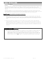
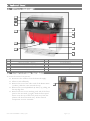
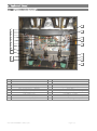
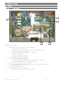
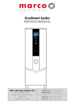
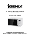
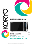
MAXIBREW 2 TWIN BOILER-BREWER SERVICE MANUAL Marco Beverage Systems Ltd. 63d Heather Road, Sandyford Industrial Estate, Dublin 18, Republic of Ireland Ireland Tel: (01) 295 2674 Ireland Fax: (01) 295 3715 UK Tel: (0207) 274 4577 UK Fax: (0207) 978 8141 CONTENTS: PAGE 1. INTRODUCTION 3 2. SAFETY INSTRUCTIONS 4 3. 3.1. 3.2. 3.3. 3.4. 3.5. 3.6. 3.7. 3.8. 3.9. 3.10. 4. 4.1. 4.2. 4.3. 4.4. 4.5. 4.5.1. 4.5.2. 4.5.3. 4.5.4. 4.5.5. 4.5.6. 4.6. 4.7. 4.8. 4.9. 4.10. 4.11. 4.12. 4.13. 4.14. BASIC INSTRUCTIONS Installation Details Operation Brewing Coffee Hot Water Lock Function Coffee Aerator Troubleshooting Maintenance Cleaning Safety 5 5 6 7 7 TECHNICAL DATA General Description External Arrangement Access to internal components Internal Arrangement PCBs PCB Layout PCB Brewer 2004 – 1600326 PCB Dual Timer – 1600323 PCB Air Pump Driver – 1600319 PCB Daughter – 1600317 PCB Brewer Display – 1600324 Operation – Heat Fill Mode Operation – Continuous Fill Mode Troubleshooting – Diagnostic guide Level Probes Elements Descaling procedure Coffee Aerator Wiring Diagram Spare Parts List 10 10 11 11 Service Manual MAXIBREW 2 TWIN 25-03-08 8 8 8 9 9 9 12 13 13 14 16 17 17 18 19 20 21 24 26 27 28 29 31 Page 2 of 31 1. INTRODUCTION: The information provided in this manual is intended to assist in the installation and maintenance of the Marco Maxibrew 2 Twin Boiler Brewer. Please read the instructions carefully to prevent accidents and ensure an efficient installation. This manual is not a substitute for any safety instructions or technical data affixed to the machine or its packaging. All information in this manual is current at the time of publication and is subject to change without notice. Only technicians or service providers authorised by Marco should carry out installation and maintenance of these machines. Marco accepts no responsibility for any damage or injury caused by incorrect or unreasonable installation and operation. Service Manual MAXIBREW 2 TWIN 25-03-08 Page 3 of 31 2. SAFETY INSTRUCTIONS: Read all instructions. To protect against electric shock do not immerse mains cord in water or other liquid. To prevent chafing of the cable, do not let the mains cord hang over the edge of a table or counter ; or touch hot surfaces. Do not operate any appliance with a damaged cord, plugs, or after the appliance malfunctions or has been damaged in any manner. Switch off at the mains (unplug or disconnect from outlet) and turn off the water supply when not in use and before cleaning. Allow to cool before removing components. The use of spares and accessories not recommended by Marco may cause damage and/or injuries. Do not use outdoors. Do not place on or near a hot gas or electric burner. Do not use the appliance for anything other than its intended use. Save these instructions. 3. BASIC INSTRUCTIONS: This is a copy of the instruction manual that goes out with every unit. 3.1. INSTALLATION DETAILS: Electrical installation: Service Manual MAXIBREW 2 TWIN 25-03-08 Page 4 of 31 Electrical specification: o 5.6kW/230V, 6.1kW/240V This needs to be connected to a 30A isolator outlet. A qualified electrician should do this. o 8.4kW/400Vac/3P+N+E This unit must be connected to a suitable 3-phase power supply. This should be done by a qualified electrician. When power is applied to the machine, a fluorescent light will come on inside the machine. The LEDs on the display PCB will flash a number of times – this indicates which version of software code is in the machine. Plumbing installation procedure: Note: Marco recommend that this machine be positioned on a counter with a drainage facility. Marco cannot be held responsible for any flood damages. Mains water pressure required (limits): 5-50psi (35-345kPa) Fit a stop Valve on a cold water line and attach a 3/4" BSP male fitting, washing machine type stop valve). Connect straight tailpiece of the inlet hose to the stop valve fitting. Make sure that the pre-attached sealing washer is fitted. Turn on the water to flush any impurities, dust etc from the inlet hose and water pipe. Allow several gallons through. Connect right-angled tailpiece of the hose to the inlet valve of the boiler (again 3/4" BSP). Make sure the sealing washer is fitted here also. Turn on water and check for leaks. (e.g. 3/4" x 1/2" 311 or Start-up: Check that all installation procedures have been carried out. Turn the water on at the stop valve and switch the power on at the isolator switch. The sight-glass lamp will illuminate. Switch the machine on by pressing the button associated to the ‘POWER’ text on the left control panel. This button should be held until the red light illuminates. The machine will automatically take in water. To switch off, press the button again. Service Manual MAXIBREW 2 TWIN 25-03-08 Page 5 of 31 3. BASIC INSTRUCTIONS: 3.2. OPERATION: Most boiler brewers will supply water and coffee in abundance. If, however, the hot water is used at a rate quicker than the machine can heat, most machines can end up serving cold coffee and water. This essentially means that the machine is being used incorrectly, and the quality of the end product is directly affected. The Marco Maxibrew 2 Twin uses the ‘Heat fill cycle’ as standard to ensure that only beverages at the correct temperature are served. If more hot water is used than the machine can heat, it simply runs out of water. After a short recovery period more water will be available at the correct temperature. Heat-fill mode (Tea and coffee at the optimum temperature): Water will be taken in until it is a safe level above the elements. At this point the water stops and heating begins. Once this quantity of water is up to temperature, another small quantity of cold water is taken in while the heating continues. This heat fill cycle maintains the correct temperature in the tank. When the machine has enough water to brew coffee, the green ‘Ready to Brew’ lights illuminate (approximately 25 minutes after start up). A brew can be selected at this point, but the machine is NOT full yet. No hot water is available out of the hot water tap. After approximately 45 minutes the heaters will shut off. The machine is now full, up to temperature and water is available from the hot water tap. Continuous Fill Mode (optional): This mode of operation is available as an option, but a service engineer is needed to make this change. The ‘Continuous fill mode’ essentially keeps the machine full of water, allowing an endless supply of water. In this mode the machine will never run out of water, but misuse (e.g. filling buckets for cleaning) can allow cold water to be served. Using hot water at a faster rate than the machine can recover will result in a considerable temperature drop in the beverage. Service Manual MAXIBREW 2 TWIN 25-03-08 Page 6 of 31 3. BASIC INSTRUCTIONS: 3.3. BREWING COFFEE: Slide out the coffee filter bowl and place a single sheet of filter paper in the bowl. Put the correct amount of ground coffee into the filter paper. Your coffee supply company may have pack sizes to suit the brews of your new Maxibrew 2 Twin; if not, as an approximate guide for your first brews: 220g-240g (8-8½oz) for a Half Brew (10 pints [5.7 litres]) 440g-480g (16-17oz) for a Full Brew (20 pints [11.4 litres]) Depending on the coffee grind and roast, and on water quality, you may have to adjust these quantities to obtain the optimum flavour. Level off the surface of coffee by gently shaking the filter bowl. Slide the coffee filter bowl into the guide rails in the brew head and push fully home. Select the correct brew on the relevant control panel (e.g. left control panel if the left urn being used) by pressing either the Half Brew switch for a 10 pint brew or the Full Brew switch for a 20 pint brew. Press the switch until the amber light illuminates. If you make a mistake press the Power switch to turn the machine off. Wait 3 seconds and turn back on again. Select the correct brew. A half brew should take around 4min30secs-5min30secs. A full brew should take around 9-11min. These depend on the set up of the machine (factory). Note: An engineer can set the machine up so that different brew times are available in each urn, for different strengths/types of coffee. Remove the filter paper with the spent grinds as soon as possible after brewing. Note: allow time for all the coffee to drain from the filter bowl before removing. A brew can be selected whenever the green ‘Ready to brew’ lights are illuminated. Left and right brews can run simultaneously (although the two brew buttons should not be depressed at exactly the same time. Press and release one brew button before doing the same on the other side). Note: Continuous brewing on both sides simultaneously can result in the machine running out of enough hot water to brew coffee. This can happen, particularly when large quantities of water are drawn off from the hot water tap (see next section). When the machine does not have enough hot water in reserve for a brew, the brew buttons are disabled and the green ‘Ready to Brew’ lights g o off. After a few minutes, the green Ready to Brew lights will illuminate and a brew can be selected once more. 3.4. HOT WATER: When the machine is full, up to 35 pints/20litres of water is available for tea etc. If all this water is used and no water is available at the hot water tap, the machine should be left for a short while to recover (Heat-fill mode). The recovery rate of this machine is approximately 1.6pints (0.9 litres) per minute for 5.6kW version and approximately 2.5pints (1.45litres) per minute for 8.4kW Note: A brew can still be selected after all the hot water has been drawn off the hot water tap. While the machine is brewing, however, the hot water recovery rate is reduced and the machine will take longer to replenish the hot water supply. Service Manual MAXIBREW 2 TWIN 25-03-08 Page 7 of 31 3. BASIC INSTRUCTIONS: 3.5 LOCK FUNCTION: The Maxibrew 2 Twin has a button lock function to prevent untrained personnel operating the machine, or accidental misuse by trained personnel. If the lock button (left hand side control panel) is pressed for approximately 6 seconds, a red light next to the button will illuminate. Both control panels are now ‘locked’. No buttons are operational when the lock function is enabled. The machine will operate as normal, i.e. if the machine is brewing, it will continue to brew. Once completed another brew cannot be selected until the lock is disabled. Note: The ‘Ready to Brew’ lights will still be on, but no brew can be selected. To disable the lock function – hold the lock button for approximately 6 seconds once again. 3.6 COFFEE AERATOR: The Maxibrew 2 Twin has an air-operated agitation system to mix coffee after a brew or after the coffee has been left standing for a period of time. Press and hold the Coffee Aerator button (right hand side control panel) for approximately 10 seconds to mix the coffee in the urns. Both urns are aerated when the button is pressed. 3.7 TROUBLESHOOTING: The Marco Maxibrew 2 Twin uses an electronic diagnostic system to help determine faults. If an error is detected a sequence of flashes is displayed through the POWER light. This sequence is repeated (cycled) until: 1) The problem is rectified by an engineer, or 2) In the case of the 6 flash cycle – the machine senses that normal operation has resumed, and the flash sequence ceases. The number of flashes in a cycle corresponds to the symptom in the table below: Note: Some of the error sequences will be displayed if there is low water pressure. Please check that there is water pressure and that the water stop -valve is open before calling your service agent. Status/Diagnostic light guide: No of flashes Symptom Action required 2 Water level below elements. Normal when machine first fills. Check water pressure, if this is OK - call service agent. 3 Temperature sensor failure (o/c) Call service agent 4 Water not heating Call service agent 5 Temperature sensor failure (s/c) Call service agent 6 Machine not filling Check water pressure. If this is OK and the machine has not returned to normal operation after 15 min – call service agent Service Manual MAXIBREW 2 TWIN 25-03-08 Page 8 of 31 3. BASIC INSTRUCTIONS: 3.8. MAINTENANCE: Marco machines have been designed to give many years of trouble free service. Marco Beverage Systems design, manufacture and test to ISO9001:2000 standard. The only regular maintenance required is occasional de-scaling. In common with all water boiler manufacturers, service calls resulting from limescale are not covered by warranty. Fitting a scale reducer is recommended, especially in hard water areas. This can reduce the buildup of scale but may not stop it altogether. A service engineer should descale the machine regularly. The frequency that descaling is required depends on the local water supply; hard water areas need more attention. Marco suggest that the machine be descaled every 3 months if the unit is in a hard water area. In soft water environments every 6 months should suffice. 3.9. CLEANING: Like any cooking utensils the coffee urns of your Maxibrew 2 Twin must be cleaned properly, regularly. Marco recommend cleaning after each days brewing using a proprietary urn-cleansing compound. Marco Urn Cleanser (Marco Part number 8000240) is available in 800g tubs. Instructions are given on each tub. Your Maxibrew 2 Twin is supplied with one large urn cleaning brush and one small sight-glass cleaning brush – to ensure thorough cleaning. To clean the sightglass, unscrew the small plastic plugs on the top of the sightglass. The sightglass is fragile, so be careful while cleaning. The exterior of these machines may be cleaned with a damp cloth and a light detergent. Do not use abrasive cloths or creams, as this will spoil the finish of the machine. Do not use a water jet or spray. Beware of accidentally operating the draw off taps when cleaning the front of the machine. 3.10. SAFETY: This appliance must be earthed. Risk of flooding. The hose supplied with this unit is non-toxic food quality tested to 190psi. However, a hose is not a permanent connection. It is, therefore, advisable to switch off boiler and close the stopcock valve when boiler is not in use, e.g. overnight, weekends etc. Risk of scalding. Beware of accidentally operating the water drawoff tap especially when cleaning the front of the boiler. ALL users of this machine should be trained and should be aware that the machine dispenses very hot beverages. The utmost care has been taken in the manufacture and testing of this unit. Failure to install, maintain and / or operate this boiler according to the manufacturer’s instructions may result in conditions that can cause injury or damage to property. If in any doubt about the serviceability of the boiler always contact the manufacturer or your own supplier for advice. Service Manual MAXIBREW 2 TWIN 25-03-08 Page 9 of 31 4. Technical Data: 4.1. GENERAL DESCRIPTION: MAXIBREW 2 TWIN - 8.4kW 1000465 Electrical Connection Plumbing Fittings Pressure Dimensions Height Height incl. Cup Rail Width Depth (footprint on counter) Depth Depth incl. Drip Tray Coffee Output: 1 x Half brew: 2 x Half brew: 1 x Full Brew: 2 x Full Brew: Maximum Hourly Coffee Output: Hot Water: Immediate Draw Off: Performance 8.4kW,400V (3Phase+Neutral) c/w 1.5m flex 0.75” BSP Food grade inlet hose supplied 5-50 psi (35-345 kPa) 816mm 855mm 762mm 480mm 590mm 630mm Up to 6.8 litres (12 pints) Up to 13.6 litres (24 pints) Up to 13.6 litres (24 pints) Up to 27.2 litres (48 pints) Up to 91 litres(160pints) Heat Fill Mode: Up to 20 litres (35 pints)when full. Continuous Fill Mode: 6 litres (10.5pints) recommended max. 80 litres/hr (141pints/hr) Total Recovery rate at 8.4kW: MAXIBREW 2 TWIN – 5.6kW 1000464 Electrical Connection Plumbing As above Dimensions Performance As above Coffee Output: 1 x Half brew: 2 x Half brew: 1 x Full Brew: 2 x Full Brew: Maximum Hourly Coffee Output: Hot Water: Immediate Draw Off: 5.6kW,230V (Single Phase) c/w 1.5m flex Up to 6.8 litres (12 pints) Up to 13.6 litres (24 pints) Up to 13.6 litres (24 pints) Up to 27.2 litres (48 pints) Up to 54 litres(96pints) Heat Fill Mode: Up to 20 litres (35 pints)when full. Continuous Fill Mode: 5 litres (8.5pints) recommended max. 50 litres/hr (88pints/hr) Total Recovery rate at 5.6kW: Service Manual MAXIBREW 2 TWIN 25-03-08 Page 10 of 31 4. Technical Data: 4.2. EXTERNAL ARRANGEMENT: 1 2 3 12 4 11 10 5 9 8 6 7 No. 1 2 3 4 5 6 4.3. Description Cup Rail Acrylic MB2 Twin - (1801515) Plastic Fascia MB2 - (1801550) Basket Complete MB2 - (2300075) Control Panel Left Coffee Tap - (2100290) Hot Water Tap - (2100275) No. 7 8 9 10 11 12 Description Drip Tray Curved Splashback Plastic Rose MB2T - (1801560) Front Panel Control Panel Right Urn Lid - (2300350) ACCESS TO INTERNAL COMPONENTS: To access the internal components: Disconnect the machine from the electrical supply. Allow to cool sufficiently. Remove the screw from under each of the Plastic Roses (9 above). Slide the roses towards the tap. Remove the Curved Splashback (8 above) by pulling out the top edge first. Remove the two screws attaching each side of the front panel to the surround. (13 right). Slide the front panel down. Lever the top of the front panel away from the plastics. Lift the Front Panel away. All the internal components are now accessible. Service Manual MAXIBREW 2 TWIN 25-03-08 13 Page 11 of 31 4. Technical Data: 4.4. INTERNAL ARRANGEMENT: 20 1 2 3 4 5 6 7 8 9 19 18 17 16 15 14 13 10 11 12 No. 1 2 3 4 5 6 7 8 9 10 Description PCB Brewer Display Left - 1600324 Brew Level Probe Assembly PCB Brewer 2004 - (1600326) PCB Dual Timer – (1600323) PCB Air Pump Driver – (1600319) Sightglass - (1700250) Connector Blocks Tank Overflow Pipe Left Brew Pump – (1501540) Elements - (1500975) Service Manual MAXIBREW 2 TWIN 25-03-08 No. 11 12 13 14 15 16 17 18 19 20 Description Mains Cable Inlet Solenoid Valve – (1502170) Top Tray (Brew) Overflow pipe Right Brew Pump – (1501540) Drain Pipe Lamp and Lampholder – (1501212, 1501213) PCB Daughter – (1600317) Lamp Ballast – (1501211) Low Level and High Level Probe Assembly PCB Brewer Display Right- 1600324 Page 12 of 31 4. Technical Data: 4.5. PCBs: 4.5.1. PCB Layout: 2 1 3 4 5 INTERNAL PCB LAYOUT: 1. 2. 3. 4. 5. PCB Brew Board (Twin 2004) (Marco part no. 1600326) Controls the heater switching Switches one element only (daughter PCBs switch the other elements) Controls the water inlet switching Controls tank temperature/temperature adjustment Controls water level Outputs to the Dual Timer PCB Outputs to the Daughter PCBs PCB Dual Timer (Marco part no. 1600323) Controls the brew pump timing Controls the Display PCBs (Buttons and LEDs not shown- 1600324) Controls and Outputs to the Air Pump Driver PCB PCB Air Pump Driver (Marco part no. 1600319) Controls the switching of the air pump for the coffee aerator/agitator function PCB Daughter (Marco part no. 1600317) Switches one element PCB Daughter (Marco part no. 1600317) Switches one element, only one PCB on 5.6kW Service Manual MAXIBREW 2 TWIN 25-03-08 Page 13 of 31 4. Technical Data: 4.5. PCBs: 4.5.2. PCB Brewer 2004 (1600326): 1 2 3 4 5 24 6 23 7 22 21 8 20 9 19 18 17 10 16 11 15 14 13 12 COMPONENTS OF PCB BREWER 2004: 1. 2. 3. 4. 5. 6. Transformer Power On/Off – 2way connector (low voltage) Looped on this machine – power switch controlled through Display PCB and Dual Timer LEDs - 5way connector (low voltage) Not used on this machine Data I/O – 4way (low voltage) Connects to the Dual Timer PCB Earth Tab Mode of Operation selector – Heat Fill / Continuous Fill The default position is no jumper or jumper towards the transformer side. The default mode is HEAT-FILL. To change the mode to CONTINUOUS FILL move the jumper so that the two pins furthest away from the transformer are connected. Service Manual MAXIBREW 2 TWIN 25-03-08 Page 14 of 31 4. Technical Data: 4.5. PCBs: 4.5.2. 7. 8. 9. 10. 11. 12. 13. 14. PCB Brewer 2004 (1600326): Water Level – 5way connector (low voltage) Connects to Low level, High level and Brew level probes. Microchip Receives inputs from Data I/O (4), Mode select jumper (6), Water Level Probes (7), Thermistor (11), Temperature Range Jumper (10), Temp adjust Pot (9) and Power On – 2way (2). Outputs to Data I/O (4), LEDs (3), Daughter PCBs Connector (12), Triac(15)/Heater Relay(13)/Safety Heater Relay(14), Inlet solenoid Relay (21) Temperature Adjust Pot To increase temp – adjust clockwise; to decrease temp adjust anti-clockwise Temperature Range Jumper Controls three temperature ranges – should be on middle pins Thermistor Connector Daughter PCB Connector (low voltage) Connects to Daughter PCBs – allows switching of more than one element Relay - Heater Switches the element Relay - Heater Safety Backup relay for element – controls the switching should the triac fail 15. Triac In parallel with the heater relay. Switches the element initially. (Zero voltage switching) This lengthens the life of relays, by removing the arc (flash) during switching which wears the contacts on the relay. 16. Heater/Element Tab (high voltage) Connects to the element 17. Live Mains Tab (high voltage) 18. Inlet Solenoid Tab (high voltage) Connects to the inlet solenoid 19. Live tab – spare (high voltage) 20. Suppressor 21. Relay – Inlet Solenoid Switches the inlet solenoid 22. Fuse 23. Neutral Mains tab (high voltage) 24. Neutral Mains tab – spare (high voltage) Service Manual MAXIBREW 2 TWIN 25-03-08 Page 15 of 31 4. Technical Data: 4.5. PCBs: 4.5.3. PCB Dual Timer (1600323): 18 17 16 15 1 14 2 13 3 12 4 11 5 6 7 8 9 10 COMPONENTS OF DUAL TIMER: 1. 2. 3. 4. 5. 6. 7. 8. 9. 10. 11. 12. 13. 14. 15. 16. 17. 18. Connector 4way (low voltage) connects to Data I/O 4way connector on the Brewer PCB (see section 4.5.2) Microchip The version of software code is indicated when power is applied to the machine for the first time. The display PCB LEDs will flash a sequence e.g. 2 flash-pause-6flash – indicates software version 2.6 Right pump time adjust pot – VR2 turn clockwise to increase brew time on the right hand urn. Note that with the current software version, the Full brew time is double the Half brew time. Current Version 2.6 Left pump time adjust pot – VR1 turn clockwise to increase brew time on the left urn. Note that with the current software version, the Full brew time is double the Half brew time. Current Version 2.6 Live to Dual Timer (high voltage) Triac - switches the left pump Wire to left Pump (high voltage) Live to Dual Timer (high voltage) (looped to 5) Triac - switches the right pump Wire to right Pump (high voltage) Timer Mode select switches - only switch No.1 should be ON for this machine Connector for Right Display PCB – right ribbon cable Connector for Right Display PCB – middle ribbon cable Connector for Right Display PCB – left ribbon cable Connector for Left Display PCB – right ribbon cable Connector for Left Display PCB – middle ribbon cable Connector for Left Display PCB – left ribbon cable Connector for Air Pump Driver PCB Service Manual MAXIBREW 2 TWIN 25-03-08 Page 16 of 31 4. Technical Data: 4.5. PCBs: 4.5.6. PCB Air Pump Driver (1600319): NOTE: The PCB Air Pump Driver (1600319) is a PCB Solenoid Driver (1600311) with the suppressor removed. If a spare PCB is sent with the suppressor attached, use snips to remove the suppressor before attaching the PCB 1 2 3 4 1 COMPONENTS OF AIR PUMP DRIVER (1600319) 1. Connector Ribbon Cable 4way (low voltage) t h The ribbon cable used to connect the PCB Dual Timer to the PCB Air Pump Driver is NOTE: i differently to any other ribbon cable on the Maxibrew 2 Twin. The 4way connector is wired s reversed on one end. This ribbon is identified by the black insulation strip. c o nnects the PCB Air Pump Driver to the J5 connector on the PCB Dual Timer. 2. 3. 4. Live Tab - connects to mains live. Load Tab - connects to Live of Air Pump Triac - switches the Air Pump 4.5.5. PCB Daughter (1600317): The PCB Daughter is used to switch an element. The triac, relay and safety relay used on the PCB Brewer is also used on the PCB Daughter. This reduces wear on components. 1. Live Tab - connects to mains live 2. 4way Connector J2 connects to next Daughter PCB 3. 4way Connector J1 connects Daughter PCB to Brewer PCB 4. Heater Tab - connects to element 1 2 3 Service Manual MAXIBREW 2 TWIN 25-03-08 4 Page 17 of 31 Service Manual MAXIBREW 2 TWIN 25-03-08 Page 18 of 31 4. Technical Data: 4.5. PCBs: 4.5.6. PCB Brewer Display (1600324): NOTE: The Left and Right PCB Brewer Displays have the same part number, but the Right PCB needs to be modified on site before it can be installed. The Button cap needs to removed off the second button (shown below). Left Display PCB 1 2 3 4 5 6 7 8 Right Display PCB 9 10 11 12 13 14 15 16 17 COMPONENTS/FUNCTIONS OF LEFT PCB BREWER DISPLAY 1. 2. 3. 4. 5. 6. 7. 8. 9. Button – Lock function LED – Lock function Button – Power ON/OFF function LED – Power ON/OFF and Status (Diagnostic flash) function LED – Ready to Brew function Button – Left Half Brew function LED – Left Half Brew function Button – Left Full Brew function LED – Left Full Brew function COMPONENTS/FUNCTIONS OF RIGHT PCB BREWER DISPLAY 10. 11. 12. 13. 14. 15. 16. 17. 18. Button – Coffee Aerator Function LED – Not Used Button – Not Used (Button cap to be removed) LED – Not Used LED – Ready to Brew function Button – Right Half Brew function LED – Right Half Brew function Button – Right Full Brew function LED – Right Full Brew function Service Manual MAXIBREW 2 TWIN 25-03-08 Page 19 of 31 18 4. Technical Data: 4.6. OPERATION – HEAT FILL MODE: Turn the water on at the stop valve and switch the power on at the wall connection. The sightglass lamps will now illuminate. Press the POWER ON button at the front of the machine. A red LED next to the button will illuminate and the machine will start to fill. This LED will flash a 2 flash cycle while the water level is below the low probe. Note: The machine will not heat until the water has reached the low level probe. When the low-level probe is reached, the water inlet is stopped and the element is switched on. This water is heated to the pre-set temperature (92– 94.5°C). The machine takes in another small body of water, while continuing to heat. This method of staggered filling (heat-fill cycle) ensures that the temperature in the tank remains within 3 degrees of set temperature. This heat-fill cycle continues until: a) the water level reaches the high level probe and b) the water temperature reaches the pre-set temperature as above. Note: When the level of water is at a safe height above the low level, the green READY TO BREW light illuminates. This indicates that the machine has enough water to run a brew and is at the correct temperature. The machine is NOT full at this level. A brew can be selected, but no water is available out of the Hot Water Tap. Unless a brew is selected, the full quantity of hot water should be available within 15/20 minutes of reaching this level. The machine is ready to brew Coffee and up to 20litres of Hot Water is available for immediate draw-off when the machine is full and up to temperature. There is one large water tank, with two urns recessed into it. When a brew is selected, hot water is pumped from the tank up to a sprayhead and into the filter basket. The coffee runs out of the filter basket into the urn. Since the water tank surrounds the urn, the brewed coffee is kept at temperature. The heat fill cycle ensures that the temperature in the tank does not drop by more than 3 degrees. The machine will only allow small amounts of cold water into the tank, while continuing to heat to ensure that the temperature does not drop too low. If more hot water is used than the machine can recover (approx 0.9l/min @ 5.6kW ; approx 1.4l/min @ 8.4kW), the amount of water in the tank decreases. If the full quantity of Hot Water is drawn off, the machine will take approximately 15min to recover back up to the high level probe. Note: brews can still be selected when no Hot Water is available out of the tap. This is due to a buffer of hot water beneath the level of the ‘hot water stand pipe’ inside the tank. These should preferably be half brews rather than full brews to ensure shorter recovery times. When two brews are running simultaneously, the level of the water in the tank does drop slowly, because the machine is using water at a quicker rate than it can heat. If dual brews are selected at a point where there is no water available at the hot water tap, the level of water will drop off the BREW SAFETY LEVEL PROBE. If the water level is below this probe – a new brew cannot be selected. The current brews will be completed, but a recovery period will be necessary before brews can be selected, or hot water is available. After a recovery period (up to 15min), the machine will be ready to brew once again. Note: a longer recovery is required before any substantial amount of Hot Water can be drawn off. In the HEAT-FILL mode - drawing off Hot Water while brewing Coffee should not affect the quality of the brew. The machine naturally gives priority to the coffee. The machine will effectively run out of hot water (no water will be available out of the hot water tap), but brews can still be selected. Service Manual MAXIBREW 2 TWIN 25-03-08 Page 20 of 31 4. Technical Data: 4.7. OPERATION – CONTINUOUS FILL MODE: NOTE: The standard operation mode for this machine is the Heat Fill cycle. The Continuous Fill cycle can be selected by moving the Jumper J12 on the Brewer PCB (above the microchip) to the position furthest away from the transformer. See Section 4.5.2. Turn the water on at the stop valve and switch the power on at the wall connection. The sightglass lamps will now illuminate. Press the POWER ON button at the front of the machine. A red LED next to the button will illuminate and the machine will start to fill. Note: The machine will not heat until the water has reached the low level probe. When the water level is below the low probe, the Power LED flashes the diagnostic 2 flash cycle. When the low-level probe is reached the element is switched on. The machine continues to fill until the high level probe is reached. This means that the machine is full of cold water at this point. The water is heated to the pre-set temperature (92– 94.5°C). The continuous fill cycle is complete when the green Ready to Brew light is on. A brew can now be selected. Note: Once again – the Green ‘Ready to Brew’ light indicates that the machine is at a safe level and up to temperature, but in this case the water has filled to the high probe already, so the machine will be full and up to temperature when the light comes on for the first time. Unlike the Heat-Fill mode, the machine will fill with mains water as soon as the water level drops off the high level probe. The machine will always be full of water, but the drawback is that if operators draw off too much water from the hot water tap, the temperature of the beverages can be affected. The brew temperature will not drop significantly while brewing, even when doing dual brews – BUT - if a large amount of hot water is used at the same time, brew temperatures can be affected, because cold mains water replaces the hot water used immediately. Service Manual MAXIBREW 2 TWIN 25-03-08 Page 21 of 31 4. Technical Data: 4.8. TROUBLESHOOTING – DIAGNOSTIC GUIDE: The Marco Maxibrew 2 Twin uses an electronic diagnostic system to help determine faults. If an error is detected a sequence of flashes is displayed through the POWER light –shown in the picture below. The length of time and recovery method of each of these flashing displays is detailed below: 2 FLASH CYCLE – BELOW LOW LEVEL Display pattern: 2 quick flashes then a short pause - repeated. Electronic check and action: This indicates that the low level circuit is open i.e. the probe is not in contact with the water. The element is switched OFF at this stage and the inlet is left ON. (note that if this is a low probe wiring fault, the water will stop at the high level probe regardless of the status of the low level). This is a recoverable error i.e. the machine does not need to be reset when the problem is solved. (e.g. if a closed mains water stop valve is the problem, opening the valve will allow water into the machine and normal function will resume when the low level probe is reached) Probable causes: 1. The water level is below the low level probe, which is normal when the machine fills for the first time. (Can be flashing for up to 5 min at start up) 2. The low level probe wire is disconnected, or there is another wiring fault (eg. a bad earth (return) connection between the PCB and the Tank) Action required: 1. Check that the water pressure is OK and ensure that the stop valve is open. 2. Check that the inlet solenoid is working. 3. If the water level is above the level of the low probe, check the probe circuit wiring 4. Technical Data: 4.8. TROUBLESHOOTING – DIAGNOSTIC GUIDE: 3 FLASH CYCLE – THERMISTOR OPEN CIRCUIT Display pattern: 3 quick flashes then a long delay (up to 15 seconds) - repeated. Electronic check: This indicates that the Thermistor is measuring such a large resistance that it assumes the thermistor circuit is open. Service Manual MAXIBREW 2 TWIN 25-03-08 Page 22 of 31 The element and inlet valve are turned OFF when this error is detected This is a recoverable error. When the correct range of resistance is measured, normal operation resumes Probable causes: 1. The thermistor probe is unplugged from the 4way connector on the PCB or the thermistor has failed open circuit. Action required: 1. Check that the thermistor is plugged in to the PCB correctly. If it is, replace the thermistor. 4 FLASH CYCLE (Heat Fill Mode Only) – NOT HEATING Display pattern: 4 quick flashes then a short pause - repeated. Electronic check: This checks that the temperature is increasing when the heater is on. Measures the rate that the temperature increases in a specified time. This error is only displayed after 20 mins of the heater being on continuously. When the error is detected, the element and inlet valve are turned off. This is a non recoverable error. The machine needs to be reset when this problem is solved. Probable causes: 1. All the elements have failed 2. Wiring fault Action required: 1. Check that the resistance on the elements. If there is a reasonable resistance (15-25Ω)on the element it probably has not failed, so the wiring might be at fault. NOTE: for this error to be displayed all elements would have to fail. 5 FLASH CYCLE – THERMISTOR SHORT CIRCUIT Display pattern: 5 quick flashes then a short pause - repeated. Electronic check: This indicates that the Thermistor is measuring zero resistance. It assumes the thermistor has failed sort circuit. The element and inlet valve are turned OFF when this error is detected This is a recoverable error. When the correct range of resistance is measured, normal operation resumes. Probable causes: 2. The thermistor has failed. Action required: 2. Replace the thermistor. 4. Technical Data: 4.8. TROUBLESHOOTING – DIAGNOSTIC GUIDE: 6 FLASH CYCLE (Heat Fill Mode Only) – NOT FILLING Display pattern: 6 quick flashes then a short pause - repeated for approx 2min. Then normal function resumes for 1min30secs – then flashes for 2min again – this cycle is repeated. Electronic check: This checks that the inlet solenoid valve is not kept ON for more than 1min30secs when in the heat fill cycle. Note: this error is only checked once the water level has reached the low level probe and the machine has begun the heat fill cycle. This is a recoverable error. In the heat fill cycle, even with reasonably low water pressure the inlet solenoid valve usually only stays ON for approx 5-6 seconds. If the inlet valve stay ON for more than 1min30secs, there is a problem with the inlet valve or the mains water supply. After 1min30seconds the 6 flash cycle is displayed for 2min – the inlet solenoid valve is turned OFF during this time. After this 2min cycle, normal operation resumes i.e. the machine attempts to fill by opening the inlet solenoid valve once more. If after 1min30secs no water has come into the machine, the 6flash sequence is displayed again. This cycle is repeated. Service Manual MAXIBREW 2 TWIN 25-03-08 Page 23 of 31 Probable causes: 1. Mains water pressure problem or the mains water stop valve is closed. 2. Inlet solenoid valve failure. Action required: 1. Check the mains water supply. If it is good, wait 5minutes to check that the error cycle is continuing. 2. If the mains water supply is good, check that the inlet solenoid valve is working. 4. Technical Data: 4.9. Level Probes The level probes provide much of the control inputs into the PCB and are critical to the operation of the machine. The wiring to these should be checked regularly and the probes themselves should be cleaned whenever the machine is serviced. There are 3 level probes on the Maxibrew 2 Twin. Low Level Probe High Level Probe Brew Level Probe The high and low level probes are are mounted on one assembly on the top right side of the tank. The brew level probe is mounted on the top left side of the tank. The pictures below show how to remove these assemblies: Removal of the Low and High Level Probe assembly Service Manual MAXIBREW 2 TWIN 25-03-08 Page 24 of 31 Removal of the Brew Level Probe assembly 4. Technical Data: 4.9. Level Probes The Level Probe assemblies are shown in the picture. All the probes are mounted above the water line and have stainless steel tabs that hang down to the level required. Low and High Level Probe Assembly (left in picture): The low level probe has the longest tab - 290mm. When in position, the bottom of the tab rests in a safe position above the elements The high level probe has the shortest tab – 40mm. The Brew Level Probe Assembly (right in picture) The brew level probe has a 190mm long tab. A brew can be selected and will complete safely when the water level has reached this probe. A brew cannot be selected below this level. Service Manual MAXIBREW 2 TWIN 25-03-08 Page 25 of 31 4. Technical Data: 4.10. Elements Removing the elements: Drain the machine: o remove the top hoseclip off the drain hose loop (1 in picture below) o carefully pull the hose off the top elbow o squeeze the silicon hose near the bottom and quickly pull the upper part of the hose out from the machine and place in the drain facility Remove the element assembly/clean out door (2 in picture below) by unfastening the 8 brass nuts. Slide the element assembly through the clean out opening. 1 2 The element assembly consists of three 2.8kW 230V elements attached to the stainless steel clean out door (see below). The thermistor pocket is welded into the clean out door. When reassembling the clean out door/ element assembly ensure that the red silicon o-ring is not damaged and the tank is well sealed. Check this carefully while the machine is heating up. Service Manual MAXIBREW 2 TWIN 25-03-08 Page 26 of 31 4. Technical Data: 4.11. Descaling Procedure To descale the machine thouroughly: Follow the instructions for removing the elements Attempt to remove as much scale as possible by hand, through the clean out door (see below). Note: ensure that internal components are protected if a hose is going to be used to flush the tank Replace the element assembly and switch on the machine. Remove the cup rail and lid of the machine.Add a descale solution to the tank through the large sprayhead hose (shown below). This runs directly into the top of the tank. Wait 20 minutes before draining and flushing the tank again. 4. Technical Data: 4.12. Coffee Aerator The coffee aerator pump can be accessed by removing the cup rail and lid of the brewer. It is located at the back of the machine (see below). The air flow can be adjusted by rotating the knobs. Service Manual MAXIBREW 2 TWIN 25-03-08 Page 27 of 31 4. Technical Data: 4.13. Wiring Diagram’s Service Manual MAXIBREW 2 TWIN 25-03-08 Page 28 of 31 Service Manual MAXIBREW 2 TWIN 25-03-08 Page 29 of 31 Service Manual MAXIBREW 2 TWIN 25-03-08 Page 30 of 31 4. Technical Data: 4.14. Spare Parts List Part Number 1600326 1600323 1600317 1600319 1600324 1501540 1501535 1502170 1600691 1500975 1501211 1501212 1501213 2301300 2301330 2301325 2100275 2100290 2100155 2100185 1401170 1400550 1700250 1801560 1801550 2300075 2300350 2300185 8000240 1801515 Description PCB Brewer 2004 PCB Timer Dual 2004 PCB Daughter PCB Air Pump Driver PCB Brewer Display Pump Nikkiso Air Pump Valve Inlet Solenoid Thermistor Assembly Element 2.8kW 230V (m-shape) Lamp Ballast Lamp Holder Lamp 5W High Level Probe Assembly Low Level Probe Assembly Brew Level Probe Assembly Hot Water Tap (with chrome body) Coffee Tap (with chrome body) Tap Assembly – Hot Water Tap Assembly - Coffee Nut Chromed for Tap Circlip for Tap Sightglass Plastic Rose (around Tap) Plastic Fascia MB2T Basket Complete MB2 Urn Lid Complete Drip Tray Complete Maxibrew 2 Twin Urn Cleanser (800g Tub) Cup Rail Acrylic Service Manual MAXIBREW 2 TWIN 25-03-08 Page 31 of 31