1
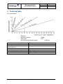
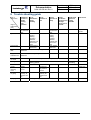
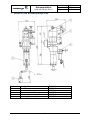
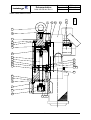
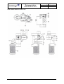
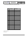
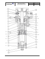
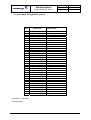
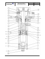
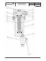
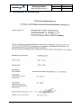
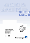
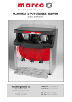
Operating instructions and spare
parts list
DOK-268-GB
Rev. 1
designation
airless spray appliance
type
4-50
Order-No.: 7200-000
- keep for further use -
Dokumentation
DOK-268-GB.doc Rev.0
Bezeichnung
Typ
Artikel
HD-Pumpe
4-50
7200-000
Caution!
Use the high-pressure pump only with dry, unlubricated compressed air!
The Airless process
Atomization and agent application are brought about without the use of air, thus the
term Airless. The agent is being atomized by squeezing it under an extremely high
pressure through the small bore of the material nozzle. In the process the agent is
disintegrated into individual particles.
The pressure required for the Krautzberger Airless process may attain up to 480bar
and is generated by compressed air operated positive-displacement piston pumps.
Advantages of the Airless spray
upgrated spray performances
instant surface coating due to a full and saturated homogeneous spray pattern
and instant film formation
reduced spray time
increased material yield due to minimized spray fogs and low material
rebound.
fatigueless working brought about by a light and handy spray gun design
equipped with only on material supply hose
optimized atomisation even of high viscous materials
1 Method of operation of the positive-displacement pump
By means of an independently controlled air motor which is alternately applying
pressure onto the motor piston, the recuperator piston of the pump is moved upwards
and downwards.
Air motor and recuperator piston are interconnected via an coupling system.
Whilst moving upwards the suction valve is opened and the agent is sucked into the
lower chamber of the hydraulic unit. Simultaneously the pressure valve located in the
piston is being closed and the recuperator piston feeds the agent into the hydraulic
unit.
The set spray pressure and the adopted nozzle size determine the stroke frequency,
the air consumption. and thus the respective spray performance of the positivedisplacement pump.
All agent conveying pump components consist of special steel 18/8
2 Mounting and installation
The Airless pump is to be installed in such a way as to render it easily accessible for
maintenance and cleaning purposes.
The pump holder is provided with an earthing srew to which the ground wire must be
connected in order to ground the static charge generated by the agent flowing within
the hose.
Connect the Airless pump only with a heavy duty compressed-air supply net:
designed for a maximum compressed air consumption.
PRIOR TO START-UP, CLOSE THE PRESSURE REGULATOR OF THE AIRLESS
PUMP BY COUNTER-CLOCKWISE TURNING THE HAND-WHEEL.
The piping supplying compressed air to the Airless-pump should have a nominal
width of 9.
2
Dokumentation
DOK-268-GB.doc Rev.0
Bezeichnung
Typ
Artikel
HD-Pumpe
4-50
7200-000
Furthermore we recommend to provide the compressed air supply net with an oiland water separator in order to prevent foreign bodies from penetrating into both air
motor and independently operating control system.
If need be a compressed air-oiler with deicing agent maybe installed between airless
pump and oil/water separator.
Use only the original suction gear in order to ensure proper pump sucking.
Engage spray gun`s safety catch and connect the material supply hose at the outlet
of the high-pressure filter.
WHEN IT COMES TO MATERIAL SUPPLY HOSES WITH SAFETY CONDUCTOR
IN ORDER TO PREVENT ELECTROSTATIC CHARGES FROM BEING
GENERATED.
CAUTION:
With regard to operating the Airless pump we prefer to the safety rules edited and
published by the applicable employers liability insurance.
3 Start-up
Entirely close pressure regulator at motor
connect compressed air-hose (max. 8bar)
in case the pump is provided with a material filter, (strongly recommended by
us) a filter mesh matching the nozzle requirements must be used. See table
Fill rinsing agent into the rinsing chamber, until the sight glass shows a 70%
fillin level
Slowly open pressure regulator until air motor starts working.
Rinse the Airless pump by means of the rinsing agent in order to get the
preservatives out of the pump
put the suction hose into the spray agent
open spray gun in order to evacuate the air still contained in the system
When the spray agent starts to emerging from the spray gun, close spray gun
and set the required working pressure at the pressure regulator (max 8bar)
CAUTION!
PAY ATTENTION TO THE PRESSURE TRANSFORMATION RATIO!
Under no-load conditions the AIrless-pump must only be operated for a short time
and at a slow running level.
Otherwise motor, suction valve, piston valve and the pump sealing may be damaged.
CAUTION!
The spay jet emerging from the spray gun is dangerous. For this reason aim the
spray gun only downwards.
4 Switching off
Switching-off
Entirely close pressure regulator at motor
disconnect spray gun and render the system pressureless.
remove and clean the spray nozzle
remove suction hose out of the spray agent and put it in a thinner
slowly open pressure regulator whilst the spay gun is being opened, until the
air motor starts working
rinse spray gun and pump by means of a thinner. In the process make sure
that the motor runs at a slow level only
for rough cleaning of the filter during rinsing , shortly open the cock at filter
3
Dokumentation
DOK-268-GB.doc Rev.0
Bezeichnung
Typ
Artikel
HD-Pumpe
4-50
7200-000
Maintenance
Daily check rinsing agent level during operation. Sight glass must show a 70% filling
level.
In case the rinsing agent is contaminated by the spray agent, replace the rinsing
agent. If, after a short time only, the rinsing agent should again be contaminated or
should the rinsing agent level displayed by the sight glass increase, we recommend
to replace the gasket set, item 22 and item 30.
By replacing these gasket sets, the recuperator piston prevented from being worn out
pematurely.
We recommend to open the material filter at fixed intervals in order to clean the filter
housing, mesh inclusive.
CAUTION!
Prior to opening material filter refer to instructions
4
Dokumentation
DOK-268-GB.doc Rev.0
Bezeichnung
Typ
Artikel
HD-Pumpe
4-50
7200-000
5 Technical data
Air consumption
Example
input air pressure:
pump type:
air consumption/double stroke:
pressure transformation ratio
delivery volume/double stroke
max. recommended double
strokes/minute
max. air pressure
max. spray agent pressure in bar
recommended delivery volume
max. delivery volume
4,0bar
4-50
5.45litres
4:1
100ccm
50
8bar
32bar
5,0l/min (50 double strokes/minute)
10,0l/min (100 double strokes/minute)
5
Dokumentation
DOK-268-GB.doc Rev.0
Bezeichnung
Typ
Artikel
HD-Pumpe
4-50
7200-000
6 Trouble shooting guide
kind of
malfunction
origin of
malfunction
(unit)
drive
hydraulic unit
pump does
not start or
Stopps
running
durin
operation
no or
insufficient
pump
sucking
spray
pressure to
low
clean control
and defective
parts
high pressure
filter
insufficient
venting,
leaking
screwing
between
hydraulic unit
and suction
gear
mesh basket
obstructed
filter contaminated, check for passage and
cleanliness
high pressure
material hose
choked hose, check for passage and
cleanliness
suction gear
suction/press
ure valve
sealing sets
atomizer
nozzle
pressure
reducing
valve
compressed
air piping
spray agent
uneven
operation of
pump
pump
continues
running even
though
spray gun is
closed
pump feeds
agent into
rinsing
chamber
clean control
and defective
parts
insufficient
venting,
leaking
screwing
between
hydraulic unit
and suction
gear
mesh basket
obstructed
iced control
pump runs
too fast
worn or blocked, replace defective parts
upper gasket
set leaking
leaking gaskets
nozzle bore
choked
air pressure
too low
insufficient air
quantity, air
pressure too
low
excessive
nozzle bore
air pressure
too low
insufficient air
quantity, air
pressure too
low
viscosity too high
6
excessive
nozzle bore
Dokumentation
DOK-268-GB.doc Rev.0
7 Units of the airless-pump 4-50
Item
1
2
3
4
5
designation
motor, compl.
control unit, compl.
Hydraulic section, compl.
filter compl.
suction gear, compl.
Order No.
080-0414
080-3141
090-0008
080-0013
080-0298
7
Bezeichnung
Typ
Artikel
HD-Pumpe
4-50
7200-000
Dokumentation
DOK-268-GB.doc Rev.0
Bezeichnung
Typ
Artikel
1.1. spare parts list motor 70
Item
Order No.
designation
1
2
3
4
5
6
7200-040-0425
7200-040-0426
7200-040-0427
7200-040-0428
7200-040-0429
7200-040-0034
Lower part
Upper part
Cylinder tube
Piston
Piston rod
Tappet rod (2 pcs)
9
9
10
11
12
13
14
15
16
17
18
19
20
21
22
23
* 24
* 25
* 26
* 27
* 28
* 29
30
31
7200-080-3141
7200-080-3142
7200-040-1301
7200-020-0076
7200-030-0143
7200-040-4896
7200-030-0533
7200-030-0509
7200-030-0510
7200-030-0706
7200-030-2804
7200-030-0719
7200-030-2857
7200-030-2856
7200-030-2867
7200-040-0436
7200-010-0247
7200-010-0241
7200-010-0249
7200-010-0250
7200-010-0190
7200-010-0253
7200-040-0062
7200-020-0150
Control unit complete, 8bar pressure
Control unit complete, 6bar pressure
Bushing
Pressure spring (2 pcs)
Ring bolt
screw (2 pcs)
Screw (2 pcs)
Srew (4 pcs)
Screw
Safety disk (8 Stück)
Safety ring
Safety disk (2 Stück)
Disk (2 Stück)
Disk (2 Stück)
Disk
Disk
gasket (2 pcs)
O-Ring (2 pcs)
O-Ring
O-Ring (2 pcs)
Gasket
Gasket
coupling (2 pcs)
Spring clip
* gasket set
8
HD-Pumpe
4-50
7200-000
Bezeichnung
Typ
Artikel
Dokumentation
DOK-268-GB.doc Rev.0
HD-Pumpe
4-50
7200-000
4
26
27
9
17
14
140-0592
17.11.98
Spare parts drawing motor
12
22
2
15
17
7
16
3
5
8
29
10
19
21
11
13 17
25
28
23
18
1
31
30
6 24 20
9
Dokumentation
DOK-268-GB.doc Rev.0
Bezeichnung
Typ
Artikel
spare parts list control unit, 8bar pressure
Pos.
1
2
3
4
5
6
*7
*8
*9
* 10
* 11
12
13
14
15
16
17
18
19
20
21
22
23
24
* 25
Bestell-Nr.
7100-080-0197
7100-130-0305
7100-040-0446
7100-030-0294
7100-030-0706
7100-030-0720
7100-010-0251
7100-010-0243
7100-010-0244
7100-010-0245
7100-010-0287
7100-030-0708
7100-030-2020
7100-030-1991
7100-030-0711
7100-030-1313
7100-130-0179
7100-080-0207
7100-030-2406
7100-100-0439
7100-080-3017
7100-130-0306
7100-030-0294
7100-030-0706
7100-010-0636
Bezeichnung
Air distributor.
Control valve. (incl. Item. 21-25)
Connector
Screw (2 pcs)
Safety disk (2 pcs)
Manometer
Gasket
O-Ring
Gasket
Gasket
gasket (2 pcs)
Extension
Bend
Double nipple (2 pcs)
Silecer
Pressure reducer
Safety valve, 8 bar
Angle fitting
Fitting
pipe,length 82 mm
5
/2-way valve, cpl.
3
/2-way valve, cpl. (2 pcs)
screw (8 pcs)
Safety disk (8 pcs)
O-Ring (6 pcs)
* gasket set
10
HD-Pumpe
4-50
7200-000
Dokumentation
DOK-268-GB.doc Rev.0
Spare parts drawing control unit
11
Bezeichnung
Typ
Artikel
HD-Pumpe
4-50
7200-000
Dokumentation
DOK-268-GB.doc Rev.0
Bezeichnung
Typ
Artikel
1.2. spare parts list hydraulic system; (with built-on filter)
Pos.
Bestell-Nr.
1.
2.
3.
4.
5.
6.
7.
8.
9.
** 10.
** 11.
12.
** 13.
14.
** 15.
** 16.
* 17.
18.
19.
20.
* 21.
** 22.
23.
** 24.
* 25.
26.
* 27.
** 28.
29.
** 30.
* 31.
* 32.
33.
34.
* 35.
7100-080-0006
7100-030-0524
7100-030-0714
7100-030-0516
7100-040-0461
7100-040-0457
7100-030-2869
7100-030-0514
7100-040-0618
7100-040-0620
7100-030-2749
7100-040-0599
7100-080-0009
7100-040-0619
7100-030-0701
7100-080-0007
7100-010-0288
7100-040-0025
7100-040-0455
7100-030-1879
7100-010-0244
7100-030-1885
7100-040-0622
7100-010-0280
7100-010-0265
7100-040-0603
7100-010-0260
7100-010-0282
7100-040-0623
7100-030-1886
7100-010-0268
7100-010-0264
7100-030-2874
7100-030-0499
7100-010-0284
Bezeichnung
Pump holder
Screw
Safety disk
Thread plug
Ring
Filter panel
Disk
Screw
Upper part tube
Piston
Ball
Ball valve seat
Fastener screw
Lower part tube
Ball
Pump fastener
Gasket
Screw in socket
Rinsing chamber
Gauge
Gasket
Gasket
Adapter
Gasket
Gasket
Filter connection
Gasket
Gasket
Adapter
Gasket
Gasket
Gasket
Disk
Screw
O-Ring
* gasket set 010-0868
** wearing parts
12
HD-Pumpe
4-50
7200-000
Dokumentation
DOK-268-GB.doc Rev.0
13
Bezeichnung
Typ
Artikel
HD-Pumpe
4-50
7200-000
Dokumentation
DOK-268-GB.doc Rev.0
Bezeichnung
Typ
Artikel
1.3. spare parts list hydraulic system
Pos.
Bestell-Nr.
1.
2.
3.
4.
5.
6.
7.
8.
9.
** 10.
** 11.
12.
** 13.
14.
** 15.
** 16.
* 17.
18.
19.
20.
* 21.
** 22.
23.
** 24.
26.
* 27.
** 28.
29.
** 30.
* 31.
* 32.
33.
34.
* 35.
7100-080-0006
7100-030-0524
7100-030-0714
7100-030-0516
7100-040-0461
7100-040-0459
7100-030-2869
7100-030-0514
7100-040-0618
7100-040-0620
7100-030-2749
7100-040-0599
7100-080-0009
7100-040-0619
7100-030-0701
7100-080-0007
7100-010-0288
7100-040-0025
7100-040-0455
7100-030-1879
7100-010-0244
7100-030-1885
7100-040-0622
7100-010-0280
7100-040-0601
7100-010-0260
7100-010-0282
7100-040-0623
7100-030-1886
7100-010-0268
7100-010-0264
7100-030-2874
7100-030-0499
7100-010-0284
Bezeichnung
Pump holder
Screw
Safety disk
Thread plug
Ring
Ring clip
Disk
Srew
Upper part tube
Piston
Ball
Ball valve seat
Fastener screw
Lower part tube
Ball
Pump fastener
Gasket
Screw in socket
Rinsing chamber
Gauge
Gasket
Gasket
Adapter
Gasket
Double nipple
Gasket
Gasket
Adapter
Gasket
Gasket
Gasket
Disk
Srew
O-Ring
* gasket set 010-0868
** wearing parts
14
HD-Pumpe
4-50
7200-000
Dokumentation
DOK-268-GB.doc Rev.0
15
Bezeichnung
Typ
Artikel
HD-Pumpe
4-50
7200-000
Dokumentation
DOK-268-GB.doc Rev.0
Bezeichnung
Typ
Artikel
spare parts list filter
Pos.
Bestell-Nr.
1.
2.
* 3.
4.
** 5.
6.
* 7.
8.
8.
9.
10.
11.
12.
* 13.
7100-030-0526
7100-040-0462
7100-010-0264
7100-030-1452
7100-030-1427
7100-030-0960
7100-010-0260
7100-040-0601
7100-040-0061
7100-030-0515
7100-030-0714
7100-020-0056
7100-040-0463
7100-010-0244
Bezeichnung
Screw
intermediate piece
Gasket
Nut
Mesh
Stopp-cock
Gasket
Connection R ¼ "
Connection R ⅜ "
Srew
Safety disk
Spring
Housing, compl.
gasket
* gasket set
** wearing parts
16
HD-Pumpe
4-50
7200-000
Dokumentation
DOK-268-GB.doc Rev.0
17
Bezeichnung
Typ
Artikel
HD-Pumpe
4-50
7200-000
Dokumentation
DOK-268-GB.doc Rev.0
8 Declaration of conformity
18
Bezeichnung
Typ
Artikel
HD-Pumpe
4-50
7200-000
Dokumentation
DOK-268-GB.doc Rev.0
19
Bezeichnung
Typ
Artikel
HD-Pumpe
4-50
7200-000