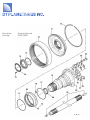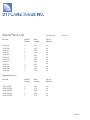
1
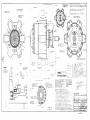
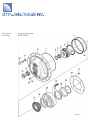
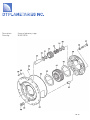
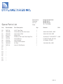
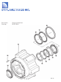
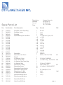
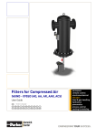
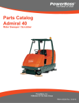
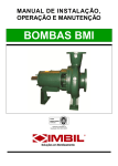
Parts & Service Manual
© DT Planetaries Inc.
for use with the DT Hub.
Published January 2009.
1 of 15
Spare Parts List
Type:
Description:
Serial no.
Date:
DTH 03/2
Planetary hub
202
12 / 12 / 2006
Contents:
Description
List
Drawing
Page
Assembly drawing
Group of cover
Group of planetary cage
Group of wheel hub
Group of axle stub
Axle List
Service Manual
-20.001.029.02
20.001.030.02
20.001.031.02
20.001.032.02
---
PLG 8002.103
20.001.030.8
20.001.031.8
20.001.032.A
20.001.033.6
---
2
3-4
5-6
7-8
9-10
11
12-15
2 of 15
3 of 15
Spare Parts List
Description:
Drawing:
List no.
Date:
Group of cover plate
20.001.030.8
20.001.029.02
12 / 12 / 2006
Pos.
Part Number
Part Description
Qty.
Remark
DIN
-1
2
3
4
5
6
7
8
9
10
11
11
11
12
13
14
15
16
17
18
19
20
21
22
23
24
25
26
27
PLG 8002.103
1180.879
1180.878
1010.821
9813.194
1130.224
7307.160
1170.716
2421.125
7316.045
1010.508
2108.064
1210.218
1210.110
7323.041
1010.168
7315.203
1180.880
9813.183
-7316.197
7331.066
5252.142
-7316.186
1220.202
1040.115
1180.505
Planetary hub compl.
Shift Piston Outer Seal
Shift Piston Inner Seal
Clutch Coupler Anchor Screw
Clutch Coupler
Axle Support Bearing
Axle Support Bearing Spacer Bushing
Cover Plate O-Ring
Cover Plate
Cover Plate Hex Bolt Washer
Cover Plate Hex Bolt
Floating Axle Adjusting Washer
ohne Pos.84 und 85
D200xD212x7.5 HNBR
140x130x7.5 HNBR
M6/D8 f7x25 12.9
7379
Floating Axle Adjusting Plug
Shift Spring Retaining Plate Screw
Shift Spring Retaining Plate
Shift Piston Wear Strip
Shift Clutch
1
1
1
4
1
1
1
1
1
12
12
1
n.B.
n.B.
1
5
1
1
1
Shift Clutch Thrust Washer
Direct Drive Shift Spring
Shift Piston
2
8
1
Clutch Assembly Retaining Washer
Retaining Washer Snap Ring
Air Chamber Drain Plug
Air Chamber Drain Plug Gasket
1
1
1
1
K45x53x20
OR 265x4. 72NBR872
16.1x30x4. C45 GEHAERTET
M16x65, 10.9
s=1.0/3.0
PS 45x55x1.0
SS 45x55x3.0
M45x1.5,5.8
M8x20. 10.9 VP n.TI-58
931
933
200x205x9,7 T51
A 100x3
M10x1 5.8 Innensechskant
A10x13x1 CU
4 of 15
471
908k
7603
Description:
Drawing:
Group of cover plate
20.001.030.B
5 of 15
Spare Parts List
Description:
Drawing:
List no.
Date:
Pos.
Part Number
Part Description
Qty.
30
31
32
33
34
35
36
37
38
39
40
41
42
43
44
45
46
47
48
49
7316.010
1210.103
1130.230
7806.081
7807.061
1170.101
7312.093
1010.536
7316.045
7821.234
7316.123
7817.051
1170.764
7313.018
8721.233
1180.541
1040.151
----
Planetary Gear Wear Plate
Planetary Gear Bearing Spacer
Planetary Gear Bearing
Planetary Gear
Planetary Gear Pin
Air Sleeve O-Ring
Air Sleeve
Planetary Cage Hex Bolt
Planetary Cage Hex Bolt Washer
Inner Planetary Cage
Sun Gear Wear Rings
Sun Gear
Planetary Plate O-Ring
Planetary Cage Shear Bushing
Outer Plantary Cage
Oil Plug Gasket
Oil Plug
10
10
10
5
5
2
1
5
5
1
2
1
1
5
1
2
2
45
46
1170.097
7323.036
O·RinglOld Style
Oil Plug/Old Style
Group of planetary cage
20.001.031.8
20.001.030.02
12 / 12 / 2006
Remark
DIN
SS 35x45x2.5
K35x45x20
Z=15
988
OR 8x3, 85-90 SHORE NBR
M16x90. 10.9 VP n.TI-58
16.1x30x4, C45 GEHAERTET
931
Z=34
OR 340x3, 72NBR872
A 27x32x2 CU
G 3/4" 5.8 Innensechskant
6 of 15
7603
908K
Description:
Drawing:
Group of planetary cage
20.001.031.B
7 of 15
Spare Parts List
Description:
Drawing:
List no.
Date:
Pos.
Part Number
Part Description
Qty.
50
51
52
53
54
55
56
57
58
59
60
61
62
63
64
65
66
67
68
69
7307.132
1160.408
1160.405
2421.123
1200231
1110.104
1110.233
7315.206
1160.409
7307.129
-----------
A.B.S. Tone Ring
Outer Grease Seal (Dirt Guard
Inner Grease Seal
Wheel Hub
Planetary and Cover Plate Align Pins
Outer Bearing
Inner Bearing
Outer Air Seal Spacer
Air Seal
Inner Air Seal Spacer
1
1
1
1
4
1
1
1
2
1
Group of wheel hub
20.001.032.A
20.001.031.02
12 / 12 / 2006
Remark
DIN
180x210x15 BASL, NBR
180x210x10 BA, NBR
16m6x60. ST GEHAERTET
D110xD17Ox38. 320 22X
JP13049A JP13010
130x160x12BA, NBR
8 of 15
6325
Description:
Drawing:
Group of wheel hub
20.001.032.A
9 of 15
Spare Parts List
Description:
Drawing:
List no.
Date:
Group of axle stub
20.001.033.B
20.001.032.02
12 / 12 / 2006
Pos.
Part Number
Part Description
Qty.
Remark
DIN
70
71
72
73
73
73
73
73
73
73
73
73
73
73
74
75
76
77
78
79
80
81
82
83
84
85
86
87
88
1220.913
7804.054
7801.042
2108.054
7317.252
7317.253
7317.254
7317.255
7317.256
7317.257
7317.258
7317.259
7317.260
7317.261
7329.124
1020.028
7814.226
1170.535
7406.004
1040.182
7306.046
1170.219
1010.559
7316.045
7333.059
1160.266
1200.414
7315.272
7315.218
Ring Gear Carrier Snap Ring
Ring Gear Carrier
Ring Gear
Spindle Bearing Pre Load Shim
1
1
1
1
n.B.
n.B.
n.B.
n.B.
n.B.
n.B.
n.B.
n.B.
n.B.
n.B.
1
1
1
2
1
1
1
1
10
10
1
1
1
1
1
SB 310
Z=66
Z=66
s=1,625 bis 2,75 je 0,125
s=1.625
s=1.75
s=1.875
s=2.0
s=2.125
s=2.25
s=2.375
s=2.5
s=2.625
s=2.75
M95x1.5
M6x16, 10.9 VP n.TI·58
912
74
75
7329.100
1020.030
Spindle Nut/Old Style
Allen Screw/Old Style
Spindle Nut
Spindle Nut Lock Screw
Spindle
Air Receiver O·Ring
A.B.S. Sensor Block
Air Receiver Ring Fitting Plug
Air Receiver Ring
Spindle Inner O·Ring
Spindle Hex Screw
Spindle Hex Screw Washer
Spindle Nut Locking Plate
Spindle Inner Oil Seal
Air Receiver Anchor Pin
Spindle mounting spacer
Spindle mounting spacer
OR 160x4. 72NBR872
1/4·18NPT keg. ", 5.8 Innenskt. 906
OR 94x3, 72NBR872
M16x1.5x50.10.9
16.1x30x4, C45 GEHAERTET
57, 15x82,55x12,7 BA
4x10
s=5,O
s=2,0
961
1481
10 of 15
Description:
Drawing:
Group of axle stub
20.001.033.B
11 of 15
Spare Parts List
Description:
Part No.
Spline
Length
Axle
Length
No. of
Splines
2206.006
2206.008
2206.011
2206.012
2206.018
2206.019
2206.020
2206.021
2206.022
2206.023
2206-024
2206.026
S
L
L
S
L
S
L
L
L
S
L
S
47.0
49.5
50.1
46.0
46.5
43.0
54.5
52.5
53.5
47.0
50.5
45.0
36
46
36
46
36
46
46
46
46
46
46
46
Part No.
Spline
Length
Axle
Length
No. of
Splines
2206.1248R
2206.02148R
2206·00852R
2206.02052R
2206.02158R
S
S
L
L
L
45.0
47.5
48.5
50.8
51.5
46
46
46
46
46
Axle List
Modified Axle List
12 of 15
Service Manual
General
1. Re-torque Wheel nuts after first 500 km to 275 ft. Ibs.
3. Remove cover plate.
2.Wheel torque to be maintained at 275 ft. lbs.
4. Remove axle.
3.Drain oil out of air chamber in cover plate every time
truck has major service job 200 to 250 hours.
5. Remove planetary plate.
6. Remove set screws from spindle nut.
Clean off old Loctite from set screws. To remove the
4.Change oil in planetary system twice a year, spring and
spindle nut will require a torque multiplier to achieve
fall. Use 75/90 100% synthetic gear oil.
approximately 1200 to 1500 Ibs-ft of torque to release
the nut.
5.Do not overfill hub with oil. Fill to 1/3 full only, between 3
and 4 o'clock.
7. Remove spacer behind spindle nut. Do not inter change
spacer with any other hub group as it is machined to set
6.If hub starts to run hot, check oil level. Drain down to 1/3
bearing pre load.
level to finish job and get to a service shop. Remove
cover plate, planetary plate and axle. Replace axle
seal inside spindle and reassemble. Fill to 1/3 with 75-90 8. Remove ring gear.
synthetic oil. At this point you should top up rear end oil
9. Remover outer bearing.
also.
Doing A Brake Job
10. Cover spline on spindle with electrical tape to protect air
seals inside hub before pulling hub off or before
installing hub with new seals. The spline will damage
1. Before dismantling hubs, check for air leaks. If you
seals if they are not taped.
discover an air leak isolate which hub and where the leak
is coming from. Air leaks out of housing breather
11. Remove complete hub.
indicate damaged air seals in hub. Air leaks out of the
back end of spindle indicate air receiver o-rings or air
12. Wash all grease oflinner bearing. Inspect bearing and
supply line damage.
replace ifneeded.
2.Drain oil.
13 of 15
Service Manual
Doing A Brake Job
13. Re - pack bearing - old one or new one with synthetic
19. Install spindle nut and torque to 1107lbs-ft or 1500 ±100
grease. To re-pack inner bearing, cover complete bearing
Nm and lock with set (allen) screws. Use blue Loctite on
with electrical lape all the way over to the air
the set (allen) screws. Install new axle seal in DT spindle.
receiver ring. Then use a grease needle between each
Push axle seal in tight against edge of original spindle.
roller and fill until grease backs up and comes out on the
Be sure 10 install axle seal with breather hole to top
open end. Do this procedure all the way around the
position.
bearing until it is all full of grease. Then remove the tape
and smear some grease on the outside surface of
20. Install planetary plate, axle and cover plate.
bearing.
21. Fill hub with 75/90 synthetic oil to 1/3 level
14. Clean grease cavity in hub and relill 2/3 full with new
synthetic grease. Always leave 1/3 to 1/2 air space in
DO NOT OVERFILL.
hub cavity.
15. If needed install new grease seals and new air seals in
hub. If no air leak found before dismantling, air seals
should be good, providing not damaged during
dismantle procedure.
16. Do your brake job.
17. Make sure spindle spline is covered with electrical tape
before installing hub on truck housing.
18. When hub is on, remove tape off spindle spline, install
bearing, ring gear and spacer ring.
14 of 15
Service Manual
Changing Axles
1. Axles are floating in housing. They require 1/8" to 3/16"
free play.
7. After the clearance is achieved fill hex plug cavity with
luberplate and install hex plug.
2. This free play is achieved by cutting off some of the
brass pin on the inside end of axle. To fine tune the free
play we use steel shims on the inside shoulder of the
center hex plug in the cover plate.
8. When installing 2 new axles on one housing. Remove
hex plugs out of cover plates first. Then remove cover
plates and axles. Install new axles with full length brass
pins. Centre both axles evenly. Measure protruding
portion of axle from edge original spindle. If axle seal is
in place add ½” to measurement.
3. Loosen hex plug in center of cover plate before removing cover plate. If hex plug is seized tight, heat with torch
and loosen. Then remove cover plate.
9. Axle should protrude 6 ½” out from edge of original
spindle. Any amount that is more than 6 ½” must be cut
off the center brass pin. This procedure should be the
4. When replacing one used axle, remove axle and measure length of brass pin. Cut brass pin on new axle to
same on both sides.
the same length and install axle.
10. Then reinstall axles and cover plates on both sides.
Install hex plug on one side. Push axles over to the side
5. Install cover plate and secure with at least 2 opposing
bolts tight. Use the end of a wooden hammer handle
that has hex plug installed.
and push the axle to the opposite side of housing and
measure from end of axle to inside shoulder that hex
11. Measure from end of axle to shoulder on cover plate that
nut bottoms out to on centre of cover plate. Record this
hex plug seats onto. Then measure inner end of hex plug
dimension. Then measure the hex plug from inner end to
to inner shoulder flange on hex plug. The difference
inner side of shoulder on plug. The plug should be 1/8" to
between these 2 dimensions is the axle free play clear3/16" shorter than the dimension of the axle position. If
ance. If the free play is not sufficient it can be adjusted
need be at this point shims can be used to achieve this
by using shims on the inside face of flange on hex plug,
clearance.
or remove axle and cut some more off brass plug on
inside end of axle. Then reinstall and go through the
same procedure to measure for axle free play.
6. When using shims try to have the same amount of
shims on each side of housing to centre axles in axle
gears.
12. Before installing hex plug in cover plate after axle is
properly sized, fill hex plug cavity with lubriplate grease.
Then install hex plug and tighten.
Installation should be complete.
15 of 15