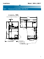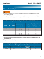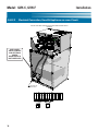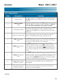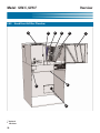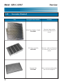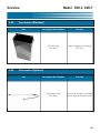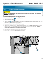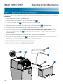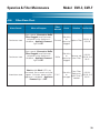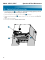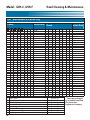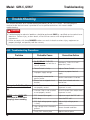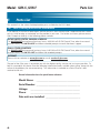
1
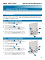
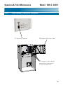
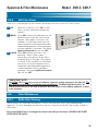
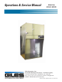
Operations & Service Manual
GVH-C &
GVH-F HOOD
Giles Enterprises, Inc.
An ISO 9001-2008 Registered Company • Committed to Quality
2750 Gunter Park Drive West • Montgomery, AL 36109 USA
Phone: 334.272.1457 • Fax: 334.239.4117 • Website: www.gfse.com
Toll Free: 800.554.4537 (USA & Canada Only)
Item No. 65877 (Release Date 4/2/12: Rev. A)
LIMITED WARRANTY
•
Subject to the terms and conditions of this Limited Warranty as herein stated, all Giles Enterprises,
Inc., Foodservice Equipment and parts purchased new from an authorized Giles Enterprises, Inc.,
representative are warranted as to defects in material or workmanship for a period of 24 months
from the date of installation, provided, however, that with regard to labor costs in connection with
this warranty, see below. All installations must be made by a qualified installing agency in accordance with all applicable codes and/or regulations in the jurisdiction in which installed. Limited warranty coverage is extended to the original owner only and is void if the unit is resold.
•
During the Limited Warranty period, Giles Enterprises, Inc. will replace or recondition, at its factory,
any part or parts of this unit which Giles Enterprises, Inc. inspectors judge defective, provided the
unit has been subjected to normal usage, properly installed, operated and serviced. This Limited
Warranty does not cover cosmetic damage, and damage due to acts of God, accident, misuse, alteration, negligence, abuse of the Giles Foodservice Equipment or the use of unorthodox repair methods. All parts replaced under this Limited Warranty carry only the unexpired term of this Limited
Warranty. Limited Warranty service may be furnished only by an authorized Giles Enterprises, Inc.,
representative.
•
If Limited Warranty service is requested, Giles Enterprises, Inc., will send factory-authorized service representatives to repair, recondition, replace or inspect units of its manufacture with such labor
being rendered without cost to owner for 24 months from the date of installation. Otherwise, service, including labor and transportation charges or other expenses, in connection with the removal or
installation of any part or parts supplied under this Limited Warranty, are specified on the original
sales contract between the purchaser and the authorized Giles Enterprises, Inc., representative.
•
Giles Enterprises, Inc. reserves the right to change or improve its equipment and parts in any way
without obligation to alter such equipment or parts previously manufactured.
•
Giles Enterprises, Inc. makes no further warranties, express or implied including implied warranties
of merchantability or fitness for a particular purpose, and has no other obligation or liability not
specifically stated herein.
•
Repair or replacement as provided under this limited warranty is the exclusive remedy. Giles
Enterprises, Inc., shall not be liable for any incidental or consequential damages for breach of any
express or implied warranty on this product, except to the extent prohibited by applicable law. Any
implied warranty of merchantability or fitness for a particular purpose on this product is limited in
duration to the duration of this limited warranty.
•
Used Giles Enterprises, Inc., Foodservice Equipment or parts or Giles Enterprises, Inc., Foodservice
Equipment or parts not purchased from an authorized Giles Enterprises, Inc., representative, carry
no warranties, express or implied.
Table Of Contents
Safety
Model: GVH-CF
........................................................v
Safety Overview . . . . . . . . . . . . . . . . . . . . . . . . . . . . . . . . . . . . . . . . . . . . . . . . . . . . . . . . . . . . . . . . . . . . v
Specific Safety Precautions . . . . . . . . . . . . . . . . . . . . . . . . . . . . . . . . . . . . . . . . . . . . . . . . . . . . . . . . . . . vi
1.
Introduction . . . . . . . . . . . . . . . . . . . . . . . . . . . . . . . . . . . . . . . . . . . . . . 1
1-01.
1-02.
1-03.
1-04.
1-04.1.
1-04.3.
1-04.4.
Construction . . . . . . . . . . . . . . . . . . . . . . . . . . . . . . . . . . . . . . . . . . . . . . . . . . . . . . . . . . . . . . 1
Standard Features. . . . . . . . . . . . . . . . . . . . . . . . . . . . . . . . . . . . . . . . . . . . . . . . . . . . . . . . . . 1
Optional Features . . . . . . . . . . . . . . . . . . . . . . . . . . . . . . . . . . . . . . . . . . . . . . . . . . . . . . . . . . 1
Specifications . . . . . . . . . . . . . . . . . . . . . . . . . . . . . . . . . . . . . . . . . . . . . . . . . . . . . . . . . . . . . 2
Overall Dimensions. . . . . . . . . . . . . . . . . . . . . . . . . . . . . . . . . . . . . . . . . . . . . . . . . . . . . . . . . 2
Regulatory Listings . . . . . . . . . . . . . . . . . . . . . . . . . . . . . . . . . . . . . . . . . . . . . . . . . . . . . . . . . 4
Hood Weights . . . . . . . . . . . . . . . . . . . . . . . . . . . . . . . . . . . . . . . . . . . . . . . . . . . . . . . . . . . . . 4
2.
Installation . . . . . . . . . . . . . . . . . . . . . . . . . . . . . . . . . . . . . . . . . . . . . . . 5
2-01.
2-02.
2-02.1.
2-02.2.
2-03.
2-03.1.
2-03.2.
2-04.
2-04.1.
2-04.2
2-04.2.1.
2-04.2.2.
2-04.2.3.
2-04.2.4.
2-05.
2-05.1.
2-05.2.
2-05.3.
2-05.4.
2-05.5.
Unpacking . . . . . . . . . . . . . . . . . . . . . . . . . . . . . . . . . . . . . . . . . . . . . . . . . . . . . . . . . . . . . . . . 5
Location . . . . . . . . . . . . . . . . . . . . . . . . . . . . . . . . . . . . . . . . . . . . . . . . . . . . . . . . . . . . . . . . . 6
Clearance to Combustibles, GVH-C . . . . . . . . . . . . . . . . . . . . . . . . . . . . . . . . . . . . . . . . . . . . 7
Clearance to Combustibles, GVH-F . . . . . . . . . . . . . . . . . . . . . . . . . . . . . . . . . . . . . . . . . . . . 8
Cooking Appliance Limitations & Clearances . . . . . . . . . . . . . . . . . . . . . . . . . . . . . . . . . . . . . 9
Limitations and Clearances, GVH-C . . . . . . . . . . . . . . . . . . . . . . . . . . . . . . . . . . . . . . . . . . . . 9
Limitations and Clearances, GVH-F . . . . . . . . . . . . . . . . . . . . . . . . . . . . . . . . . . . . . . . . . . . 10
Electrical Requirements . . . . . . . . . . . . . . . . . . . . . . . . . . . . . . . . . . . . . . . . . . . . . . . . . . . . 11
Electrical Connections . . . . . . . . . . . . . . . . . . . . . . . . . . . . . . . . . . . . . . . . . . . . . . . . . . . . . 12
Hood & Appliance Wiring Configurations . . . . . . . . . . . . . . . . . . . . . . . . . . . . . . . . . . . . . . . 13
Connection w/Interlocked Receptacle Option . . . . . . . . . . . . . . . . . . . . . . . . . . . . . . . . . . . 13
Connection w/Hood & Appliance on same Circuit . . . . . . . . . . . . . . . . . . . . . . . . . . . . . . . . 14
Connection w/ 380-480V Appliance Power Separate from 208-240V Hood Power . . . . . . . 15
Connection w/120V to 480V Appliance Power Separate from 208-240V Hood Power
using Remote Shunt Trip Device. . . . . . . . . . . . . . . . . . . . . . . . . . . . . . . . . . . . . . . . . . . . . . 16
Fire Suppression System Installation . . . . . . . . . . . . . . . . . . . . . . . . . . . . . . . . . . . . . . . . . . 17
Fire Suppression System Routing . . . . . . . . . . . . . . . . . . . . . . . . . . . . . . . . . . . . . . . . . . . . 18
Fire Suppression Fusible Link Specification & Loccation . . . . . . . . . . . . . . . . . . . . . . . . . . . 19
Fire Extinguisher Nozzle Locations. . . . . . . . . . . . . . . . . . . . . . . . . . . . . . . . . . . . . . . . . . . . 20
Fire Extinguisher Nozzle Alignment . . . . . . . . . . . . . . . . . . . . . . . . . . . . . . . . . . . . . . . . . . . 21
Final Counter-Top Installation, GVH-C . . . . . . . . . . . . . . . . . . . . . . . . . . . . . . . . . . . . . . . . . . 22
3.
Overview . . . . . . . . . . . . . . . . . . . . . . . . . . . . . . . . . . . . . . . . . . . . . . . 23
3-01.
3-02.
3-03.
3-04.
Control Panel . . . . . . . . . . . . . . . . . . . . . . . . . . . . . . . . . . . . . . . . . . . . . . . . . . . . . . . . . . . . 24
Hood Front & Filter Chamber . . . . . . . . . . . . . . . . . . . . . . . . . . . . . . . . . . . . . . . . . . . . . . . . 26
Accessories (Standard) . . . . . . . . . . . . . . . . . . . . . . . . . . . . . . . . . . . . . . . . . . . . . . . . . . . . . 28
Accessories (Optional) . . . . . . . . . . . . . . . . . . . . . . . . . . . . . . . . . . . . . . . . . . . . . . . . . . . . . 29
iii
Model: GVH-CF
Table Of Contents
4.
Operation & Filter Maintenance . . . . . . . . . . . . . . . . . . . . . . . . . . . . 31
4-01.
4-01.1.
4-01.2
4-02.
4-02.1.
4-02.2.
4-02.3.
4-02.4.
4-02.5.
4-02.6.
4-03.
4-03.1.
4-03.2.
4-03.3.
4-03.4.
4-03.5.
4-04.
4-05.
Hood Operation . . . . . . . . . . . . . . . . . . . . . . . . . . . . . . . . . . . . . . . . . . . . . . . . . . . . . . . . . . 31
Starting the Hood (Regular) . . . . . . . . . . . . . . . . . . . . . . . . . . . . . . . . . . . . . . . . . . . . . . . . . 31
Starting the Hood (ILS Model) . . . . . . . . . . . . . . . . . . . . . . . . . . . . . . . . . . . . . . . . . . . . . . . 31
Hood Filter System . . . . . . . . . . . . . . . . . . . . . . . . . . . . . . . . . . . . . . . . . . . . . . . . . . . . . . . . 32
Ventless Hood Filter Table . . . . . . . . . . . . . . . . . . . . . . . . . . . . . . . . . . . . . . . . . . . . . . . . . . 32
Filter Removal, Baffle, EAC, Charcoal. . . . . . . . . . . . . . . . . . . . . . . . . . . . . . . . . . . . . . . . . . 33
Filter Installation, Baffle, EAC, Charcoal Filter Installation . . . . . . . . . . . . . . . . . . . . . . . . . . 34
Charcoal or Baffle Filter Missing. . . . . . . . . . . . . . . . . . . . . . . . . . . . . . . . . . . . . . . . . . . . . . 34
EAC Filter Missing . . . . . . . . . . . . . . . . . . . . . . . . . . . . . . . . . . . . . . . . . . . . . . . . . . . . . . . . 34
EAC Filter Status. . . . . . . . . . . . . . . . . . . . . . . . . . . . . . . . . . . . . . . . . . . . . . . . . . . . . . . . . . 35
Filter Maintenance . . . . . . . . . . . . . . . . . . . . . . . . . . . . . . . . . . . . . . . . . . . . . . . . . . . . . . . . 35
Baffle Filter Cleaning. . . . . . . . . . . . . . . . . . . . . . . . . . . . . . . . . . . . . . . . . . . . . . . . . . . . . . . 35
EAC Filter Cleaning . . . . . . . . . . . . . . . . . . . . . . . . . . . . . . . . . . . . . . . . . . . . . . . . . . . . . . . . 36
Charcoal Filter Maintenance . . . . . . . . . . . . . . . . . . . . . . . . . . . . . . . . . . . . . . . . . . . . . . . . . 36
UV Lamp Cleaning . . . . . . . . . . . . . . . . . . . . . . . . . . . . . . . . . . . . . . . . . . . . . . . . . . . . . . . . 37
Replacing the UV Lamp . . . . . . . . . . . . . . . . . . . . . . . . . . . . . . . . . . . . . . . . . . . . . . . . . . . . 38
Filter Alarm Chart . . . . . . . . . . . . . . . . . . . . . . . . . . . . . . . . . . . . . . . . . . . . . . . . . . . . . . . . . 39
Replacing Under-Hood Fluorescent Light . . . . . . . . . . . . . . . . . . . . . . . . . . . . . . . . . . . . . . . 40
5.
Hood Cleaning and Maintenance . . . . . . . . . . . . . . . . . . . . . . . . . . . 41
5-01.
5-02.
5-03.
5-03.1.
5-03.2.
5-03.3.
5-04.
Monthly Interlock Check . . . . . . . . . . . . . . . . . . . . . . . . . . . . . . . . . . . . . . . . . . . . . . . . . . . . 41
Quarterly Hood Cleaning . . . . . . . . . . . . . . . . . . . . . . . . . . . . . . . . . . . . . . . . . . . . . . . . . . . 42
Fire Suppression System Maintenance . . . . . . . . . . . . . . . . . . . . . . . . . . . . . . . . . . . . . . . . 42
Semi-Annual Fire Suppression Maintenance . . . . . . . . . . . . . . . . . . . . . . . . . . . . . . . . . . . . 43
Annual Fire Suppression System . . . . . . . . . . . . . . . . . . . . . . . . . . . . . . . . . . . . . . . . . . . . . 43
12 Year Fire Suppression System . . . . . . . . . . . . . . . . . . . . . . . . . . . . . . . . . . . . . . . . . . . . . 43
Maintenance and Service Log . . . . . . . . . . . . . . . . . . . . . . . . . . . . . . . . . . . . . . . . . . . . . . . 44
6.
Troubleshooting . . . . . . . . . . . . . . . . . . . . . . . . . . . . . . . . . . . . . . . . . 46
6-01.
Troubleshooting Procedures . . . . . . . . . . . . . . . . . . . . . . . . . . . . . . . . . . . . . . . . . . . . . . . . . 46
7.
Parts List . . . . . . . . . . . . . . . . . . . . . . . . . . . . . . . . . . . . . . . . . . . . . . . 48
7-01.
7-02.
7-03.
7-04.
Parts Ordering and Service Information . . . . . . . . . . . . . . . . . . . . . . . . . . . . . . . . . . . . . . . . 48
Rear Electrical Components . . . . . . . . . . . . . . . . . . . . . . . . . . . . . . . . . . . . . . . . . . . . . . . . . 50
Front View, Filter & Fan Compartment . . . . . . . . . . . . . . . . . . . . . . . . . . . . . . . . . . . . . . . . . 52
Under-Hood ComponentsFilters and Switches. . . . . . . . . . . . . . . . . . . . . . . . . . . . . . . . . . . 54
iv
Safety
Model: GVH-C, GVH-F
Safety
Safety Overview
The instructions contained in this manual have been prepared to aid you in learning the proper procedures
for installing and servicing the GVH-CF Hood.
Throughout this manual, safety precautions are identified through the use of safety alert symbols and
three key words: DANGER, WARNING and CAUTION. All safety alert information will precede the
step(s) to which it applies. Suggested, recommended, or otherwise noteworthy information is identified
through the use of NOTES. Additionally, certain words are used to indicate a specific meaning or to add
emphasis.
The following words are used as indicated throughout the manual:
Shall: understood to be mandatory.
Should: understood to be advisory.
May: understood to be permissive.
Will: indicates a future event or condition is highly likely to occur.
! or !
(Safety Alert Symbol)
Used in conjunction with key words DANGER, WARNING, or CAUTION to alert you of potential personal
injury hazards and to highlight precautionary measures that pertain to subsequent step(s). Adhere to all
safety messages following these symbols to avoid possible injury or death. Failure to comply with safety
precautions identified by a safety alert symbol may also void the equipment’s warranty.
!
DANGER
• Indicates an imminently hazardous situation which, if not avoided, will result in serious injury, or even
death. Use of this is limited to the most extreme situations.
! WARNING
• Indicates a potentially hazardous situation which, if not avoided, may result in serious injury, or even
death.
! CAUTION
• Indicates a potentially hazardous situation which, if not avoided, may result in minor to moderate injury.
Also alerts against unsafe practices.
CAUTION
• When used without the safety alert symbol, CAUTION indicates a potentially hazardous situation
which, if not avoided, may result in damage to the equipment or property, and void the warranty.
NOTE:
• Identifies suggested, recommended, or otherwise noteworthy information.
v
Model: GVH-C, GVH-F
Safety
Specific Safety Precautions
For your safety, please observe the following precautions when operating or servicing the GVH Ventless
Hood. Read the following important safety information to avoid personal injury and/or damage to the
equipment or property.
!
DANGER
• Always disconnect the source of main power before removing any service panel or cover.
• Failure to ensure that the Power Switch is in the OFF position during servicing or when replacing filters
could result in damage to the equipment, electrical shock or other serious personal injury.
• Failure to comply with these DANGER notices will result in serious injury or even death, equipment or
property damage, and void the warranty.
! WARNING
• DO NOT use or store flammable liquids or materials that produce flammable vapors in the vicinity of
this or any other appliance!
• Consult a qualified electrician to ensure that all electrical requirements are met and that the unit is properly grounded.
• Before installing or servicing this equipment, read the contents of this manual thoroughly.
• Improper installation, adjustments or alterations, or improper service/maintenance could result in serious injury or even death, damage to equipment or property, and void the warranty.
• Failure to comply with these WARNING notices could result in serious injury or even death, and equipment or property damage.
! WARNING
UV MODEL ONLY
•
An internal ultraviolet radiation source is present on these models during operation.
•
Keep protective covers and panels in place during normal operation. Replace any removed after servicing.
•
An interlock circuit in the hood reduces potential for exposure to excessive ultraviolet radiation. DO
NOT attempt to disconnect or bypass this interlock.
•
Looking directly at a UV light source without proper eye protection can cause serious eye injury.
vi
Safety
Model: GVH-C, GVH-F
! CAUTION
• Maintain a minimum clearance of 18” (457.2mm) between the hood’s exhaust outlet and the ceiling, or
other overhead obstruction.
• Exercise care when lifting or moving the unit.
See Section 1-4.4, Hood Weights.
• Exercise care when removing the unit from the shipping skid.
! CAUTION
• DO NOT operate the unit unless you fully understand its components and their intended function.
• DO NOT
bend the collection fins or break the ionizer wires of the Electrostatic Air Cleaner (EAC).
Doing so will prevent it from working properly and cause a shutdown of power to the appliance being
operated under the hood.
• Failure to comply with these CAUTION notices may result in minor to moderate injury, damage
to equipment or property, and void the warranty.
CAUTION
• The electronic components of the Control Panel are somewhat impact-sensitive.
Exercise care when
performing tasks near the unit’s Control Panel to prevent possible unintentional damage.
• After cleaning the EAC, DO NOT attempt to dry the EAC cell by installing it in the hood and running the
fan to force air dry, or by running the appliance under the hood to heat dry. This could potentially damage the EAC power system, leading to failure and voiding the warranty. The EAC filter must air dry at
ambient room temperature, preferably overnight.
• When cleaning the Hood, Hood Skirt or Stand ...
••
••
••
••
DO
DO
DO
DO
NOT
NOT
NOT
NOT
steam clean.
spray with water from a hose.
use products containing chlorine.
use abrasive products, steel wool or scouring pads.
• Failure to comply with these CAUTION notices may result in damage to equipment or property, and
void the warranty.
vii
Model: GVH-C, GVH-F
Safety
NOTE:
• Giles’ responsibility for the damage to the unit ends once the freight shipment is loaded onto the carrier’s truck. Upon delivery, if the palletized unit showed any signs of damage, the entire load, including
the supplied accessories, should have been inspected immediately and any damage to the equipment
should have been promptly reported to the freight company.
• As an aid for electricians and installers, an electrical wiring diagram is provided with the unit.
Refer to
the wiring diagram during installation or while servicing.
• Comply with all appropriate state and/or local heath regulations regarding cleaning and sanitation of
foodservice equipment.
• Giles recommends the use of mild, bio-degradable, non-toxic degreasers, such as Clear Magic or
Simple Green, for cleaning parts of the hood where excessive grease film accumulation is present.
• Always ensure the unit is installed and electrically grounded in accordance with local codes, or in the
absence of local codes, in accordance with the National Electrical Code ANSI/NFPA No. 70-1984.
NOTE:
• The approximate sound level of the hood while operating is 65 dB.
NOTE:
• For some installations, it may be necessary to consult a HVAC specialist to confirm that proper room air exchange is occurring and that the on-site A/C system is
capable of handling the anticipated heat load.
• Exhaust ventilation is recommended for areas in which recirculating hoods are operated.
Giles recommends 50 CFM per linear foot of hood space. This amount could vary based on local codes and
site-specific situations.
viii
Introduction
1.
Model: GVH-C, GVH-F
Introduction
Thank You! for purchasing a GVH Series Ventless Hood System manufactured by Giles Enterprises, Inc.,
Montgomery, Alabama, USA. The GVH-C model is designed specifically for use as a counter-top hood and
is listed for the removal of grease-laden cooking vapors produced by a variety of small commercial
appliances. The GVH-F model is the Floor Stand version.
With proper care and maintenance, this unit will provide years of trouble-free service. To help protect your
investment in this equipment, we recommend taking a few moments to familiarize yourself with the
installation, operation, cleaning, and maintenance procedures described in this manual. We urge you to
read this manual before installing or operating the hood. Adherence to these recommended procedures
will minimize future potential for costly downtime and equipment repairs. Please retain this manual for
later reference.
1-1. Construction
The GVH Hood is constructed of 20-Ga & 18-Ga Stainless Steel.
1-2. Standard Features
Control Panel
• LED light cluster indicates the status and condition of the Electronic Air Cleaner (EAC) cell.
• Appliance Powered light indicates that power is being supplied to the interlocked appliance(s)
operating under the hood.
• Filter Missing light indicates that the Baffle Filter and/or the Charcoal Filter is missing or not properly
installed.
• Filter Clogged light indicates that the Baffle Filter and/or the Charcoal Filter is possibly clogged and
requires attention.
Filters
• Double Baffle Filter - captures and collects large grease particles entrained in the air stream.
• Electronic Air Cleaner (EAC) - captures and collects fine particulate air contaminates.
• Charcoal Filter - activated carbon filter helps to eliminate cooking odors.
Floor Stand Model
• Features a 61-1/2” tall Floor Stand alternative to the standard Counter-top model. Total height of Hood
and Stand is 82”.
1-3. Optional Features
Inter-Locked Start (ILS)
• Should there be a power interruption to the the hood, this system prevents the hood and the served
appliance(s) from restarting until attended by an operator. This optional provision is required by code in
certain cities and/or states.
Ultimate Ventless
• Ultra-violet Lamp Package, working in conjunction with Giles’ proven air filtration system, sanitizes the
plenum area and the exhaust air, helping to improve odor control.
1
Model: GVH-C, GVH-F
Introduction
1-3. Optional Features - Continued
Interlocked Appliance Receptacle
• Factory-installed, 50A, NEMA receptacle ready to accept the appliance power cord. This appliance
“plug-in” feature provides added convenience.
1-4. Specifications
1-4.1. Overall Dimensions - GVH-C Countertop Model
56 1/4
18 MIN. EXHAUST CLEARANCE
20 7/8 DOOR SWING
54 7/8
1 1/4
34 5/16
5 7/8
30 1/2 INSIDE
31 5/16
31 7/8 INSIDE
27 1/2
INSIDE
32
29 11/16
FRONT
RIGHT
2 1/2
EXHAUST
TOP
2
18 1/2
12
2 15/16
11
Introduction
Model: GVH-C, GVH-F
1-4.2. Overall Dimensions - GVH-F Floor Stand Model
49 15/16
20 7/8
DOOR SWING
28 1/4
6
61 1/2
82
18 MIN. EXHAUST CLEARANCE
29 5/8
INSIDE
26 1/4
INSIDE
FRONT
RIGHT
T
30 1/4
Hood Exhaust Outlet
3
Model: GVH-C, GVH-F
Introduction
1-4.3. Regulatory Listings
1-4.4. Hood Weight
4
Hood
Crated Weight
Uncrated Weight
GVH-C (Counter-Top)
290 lbs [131.5 kg]
345 lbs [156.5 kg]
Installation
Model: GVH-C, GVH-F
2. Installation
This section summarizes the procedures necessary to install your new GVH-C or GVH-F Hood. Before
installing and attempting to operate, please read the contents of this manual thoroughly. Following these
procedures will help ensure safe and proper installation.
2-01. Unpacking
!! IMPORTANT NOTE:
• If the palletized unit showed any signs of damage, you should have immediately inspected the
equipment and any other packed accessories, and promptly notified the freight company of any and all
damages. Typically, it is the customer’s responsibility to claim freight damage.
The unit is shipped on a wooden skid with protective framing, secured to the skid by high-tensile plastic
strapping and wrapped with machine applied stretch-wrap. Perform the following steps to unpack the
unit:
1. Position the palletized unit in an area with sufficient space for unpacking.
2. Cut and remove stretch-wrap and all strapping.
3. Use appropriate tools to remove the wooden crate from around the unit.
3. Remove any packed accessories from the skid and set aside. If a Floor Stand model, carefully uncrate
the Hood Stand pieces and set aside for later assembly.
4. The unit is extremely heavy. Using suitable lifting equipment or adequate manpower, lift the unit and
remove it from the shipping skid. See Section 1-4.4, Hood Weights.
5. Properly dispose of all shipping materials.
! CAUTION
•
The unit is extremely heavy and somewhat top-heavy! Exercise due caution when handling to avoid
personal injury or damage to the equipment. Take precautions not to damage the hood’s Base or
Skirting.
•
Exercise care when removing the wooden framing from around the unit to avoid any exposed nails or
staples.
•
Failure to comply with these CAUTION notices may result in minor to moderate injury, damage to
equipment or property, and void the warranty.
5
Model: GVH-C, GVH-F
2-02.
Installation
Location
! CAUTION
• DO NOT MODIFY OR ALTER THIS EQUIPMENT, OR ADD ATTACHMENTS OF ANY KIND.
NOTE:
• For some installations, it may be necessary to consult a HVAC specialist to
confirm that proper room air exchange is occurring and that the on-site A/C
system is capable of handling the anticipated heat load.
• Exhaust ventilation is recommended for areas in which recirculating hoods are operated.
Giles
recommends 50 CFM per linear foot of hood space. This amount could vary based on local codes
and site-specific situations.
NOTE:
•The sound level of the hood while operating will be approximately 65 dB.
1. Do not obstruct the exhaust air outlet. Maintain a minimum clearance of 18 inches (457.2 mm)
between the air outlet and the ceiling, or any other overhead obstruction.
2. The GVH-C Hood model is designed to sit atop a counter space. Ensure that the intended site is
structurally sound and capable of supporting the hood’s weight plus that of the appliance(s) to be
placed under it. See Section 1-4.4, Hood Weight.
3. If installing a GVH-F Floor Stand model, ensure that the floor space is fairly level. The hood stand
features adjustable legs to accomplish final leveling of the unit.
6
Installation
2-02.1
Model: GVH-C, GVH-F
Clearance to Combustibles, GVH-C Model
18" CLEARANCE
TO COMBUSTIBLES
56 1/4
18 MIN. EXHAUST CLEARANCE
20 7/8 DOOR SWING
54 7/8
1 1/4
34 5/16
5 7/8
30 1/2 INSIDE
31 5/16
31 7/8 INSIDE
27 1/2
INSIDE
32
29 11/16
FRONT
0" CLEARANCE
TO COMBUSTIBLES
0" CLEARANCE
TO COMBUSTIBLES
RIGHT
0" CLEARANCE
TO COMBUSTIBLES
7
Model: GVH-C, GVH-F
2-02.2
Installation
Clearance to Combustibles, GVH-F Model
18" CLEARANCE
TO COMBUSTIBLES
56 5/16
58 3/4
82
5 13/16
18 MIN. EXHAUST CLEARANCE
89 7/8 MIN. TO CEILING
34 5/16
20 7/8
DOOR SWING
29 5/8
INSIDE
6
32 5/16
INSIDE
36 5/8
FRONT
0" CLEARANCE
TO COMBUSTIBLES
RIGHT
0" CLEARANCE
TO COMBUSTIBLES
11
19 3/8
0" CLEARANCE
TO COMBUSTIBLES
18 1/2
12
2 1/2
2 15/16
EXHAUST
8
TOP
Installation
Model: GVH-C, GVH-F
2-03. Cooking Appliance Limitations & Clearances
2-03-1.
Limitations & Clearances, Model GVH-C
27 1/2 INSIDE
30 1/2
31 7/8 INSIDE
D
MAX.
C
MAX.
Hood is listed for Electric Appliances ONLY.
HEATING
AREA
A
MIN.
B
MIN.
A
MIN.
HEATING
AREA
APPLIANCE RESTRICTIONS
APPLIANCE
A
B
C
D
MAX. AMP.
MAX. SURFACE
AREA
MAX. SHORTENING
CAPACITY
MAX.
TEMP
MAX
ELEMENTS
FRYER(S)
1-1/2
8
N/A
19
100 TOTAL* (MAX 50AMP
THROUGH HOOD
INTERLOCK CONTACTOR)
576 SQ. IN.
140LBS/9.1 GAL
N/A
N/A
GRIDDLE
3-7/8
8-3/4
19
N/A
35
480 SQ. IN.
N/A
450F
N/A
RANGE
4
8-3/4
19
N/A
N/A
N/A
N/A
4
OVEN
1
8-3/4
19
N/A
N/A
N/A
500F
N/A
CONVEYOR
OVEN
5-1/2
8
19
N/A
44 TOTAL ALL BURNERS
55 TOTAL* (MAX 50AMP
THROUGH HOOD
INTERLOCK CONTACTOR)
55 TOTAL* (MAX 50AMP
THROUGH HOOD
INTERLOCK CONTACTOR)
N/A
N/A
500F
N/A
TOASTER
1
8-3/4
19
N/A
N/A
N/A
500F
N/A
55 TOTAL* (MAX 50AMP
THROUGH HOOD
INTERLOCK CONTACTOR)
* Appliance(s) exceeding 50 Amps must have a separate circuit from the Hood, but intelocked
through the Hood contactor coil.
9
Model: GVH-C, GVH-F
2-03-2.
Installation
Limitations & Clearances, Model GVH-F
Hood is listed for Electric Appliances ONLY.
29 5/8 INSIDE
HEATING
AREA
A
MIN.
A
MIN.
D
MAX
C
MAX.
A
32 1/4 INSIDE
HEATING
AREA
B
MIN.
APPLIANCE RESTRICTIONS
APPLIANCE
A
B
C
D
MAX. AMP.
MAX. SURFACE
AREA
MAX. SHORTENING
CAPACITY
MAX.
TEMP
MAX
ELEMENTS
FRYER(S)
5/16
8
N/A
19
100 TOTAL* (MAX 50AMP
THROUGH HOOD
INTERLOCK CONTACTOR)
576 SQ. IN.
140LBS/9.1 GAL
N/A
N/A
GRIDDLE
2-11/16
8-3/4
19
N/A
35
480 SQ. IN.
N/A
450F
N/A
RANGE
2-7/8
8-3/4
19
N/A
44 TOTAL ALL BURNERS
N/A
N/A
N/A
4
N/A
N/A
500F
N/A
OVEN
1
8-3/4
19
N/A
55 TOTAL* (MAX 50AMP
THROUGH HOOD
INTERLOCK CONTACTOR)
CONVEYOR
OVEN
5-1/2
8
19
N/A
55 TOTAL* (MAX 50AMP
THROUGH HOOD
INTERLOCK CONTACTOR)
N/A
N/A
500F
N/A
TOASTER
1
8-3/4
19
N/A
55 TOTAL* (MAX 50AMP
THROUGH HOOD
INTERLOCK CONTACTOR)
N/A
N/A
500F
N/A
* Appliance(s) exceeding 50 Amps must have a separate circuit from the Hood, but intelocked
through the Hood contactor coil.
10
Installation
2-04.
Model: GVH-C, GVH-F
Electrical Requirements
! WARNING
•
Consult a qualified electrician to ensure that all electrical specifications have been met and that the
unit is properly grounded.
•
Improper installation, adjustment, alteration, service or maintenance could result in serious injury or
even death, damage to equipment or property, and void the warranty.
Power Rating for Hood & Appliance** on Same 208-240V Circuit
Voltage
Hz
Phase
208-240
60
1 or 3
Field Provided Appliance
Power (Amps)
Hood Power
(Amps)
Branch Circuit Protector
(Amps) if Connecting
Hood & Appliance on
Same Circuit
0 - 10.5
10.6 - 14.5
14.6 - 22.5
22.6 - 38.5
38.6 - 46.5
46.7 - 50*
1.5
1.5
1.5
1.5
1.5
1.5
15
20
30
50
60
70
* Appliance(s) exceeding 50 Amps must have a separate circuit from the Hood, but intelocked through the
Hood contactor coil.
** Appliance provided and rated separately from Hood.
Power Rating for Hood Only, if Appliance is on Separate Circuit & Interlocked
Through Separate Contactor
Voltage
Hz
Phase
208-240
60
1
Hood Power
(Amps)
1.5
Breaker
15
11
Model: GVH-C, GVH-F
2-04.1.
Installation
Electrical Connections
! WARNING
•
•
All electrical installation should be performed by a qualified electrician or technician.
Improper installation or poor work practices could result in serious injury or even death, damage to
equipment or property, and void the warranty.
1. Install appropriate circuit breaker in Main breaker box.
2. Remove rear Hood Cover and Back Skirt Panel.
3. Connect appropriately sized wire (supplied by customer) from breaker box to Hood. Allow sufficient
cord length to allow moving hood, if necessary for future service or maintenance.
4. Connect Hood and Appliance wiring to Hood terminal blocks. Several different wiring configuration
options are possible depending on specific installation situations and appliance choices. See Section
2-04.2 for specific details of these options.
5. Replace all panels and covers.
6. Turn on Main Breaker.
7.
Place the Hood Power Switch in the ON position; Hood fan will start. For ILS model hood, press and
hold the “Push to Start” button on the Control Panel for approximately 5 seconds to start fan.
• If using a remote contactor (Section 2-04.2.4), the contactor must be a UL Listed, definite purpose
AC resistive air heating type, suitable for the appliance load. Installation and connections shall be in
accordance with the National Electric Code NFPA 70.
12
Installation
Model: GVH-C, GVH-F
2-04.2.
Hood & Appliance Wiring Configurations
2-04.2.1
Electrical Connection w/Interlocked Receptacle Option
APPLIANCE POWER FROM RECEPTACLE LOCATED IN HOOD. APPLIANCE AND
HOOD POWER ON SAME CIRCUIT BREAKER (USING HOOD SHUNT TRIP
CONTACTOR INCLUDED IN HOOD)
HOOD AND APPLIANCE POWER
G A1 A2 A3 AN L1 L2 L3 LN G
H H C C C
G
1 2 1 2 3
CE
13
Model: GVH-C, GVH-F
2-04.2.2
Installation
Electrical Connection, Hood & Appliance on same Circuit
208-240V APPLIANCE AND 208-240V HOOD POWER ON SAME CIRCUIT
BREAKER
USE LIQUIDTIGHT CONDUIT
AND FITTINGS
WHEN
RECEPTACLE IS
NOT INSTALLED
APPLIANCE AND
HOOD POWER
G A1 A2 A3 AN L1 L2 L3 LN G H H C C C G
1 2 1 2 3
CE
CE
1
14
Installation
2-04.2.3
Model: GVH-C, GVH-F
Electrical Connection, 380-480V Applance Power Separate from
208-240V Hood Power
380-480V APPLIANCE POWER SEPERATE FROM 208-240V
HOOD POWER (USING HOOD SHUNT TRIP CONTACTOR
INCLUDED IN HOOD)
USE LIQUIDTIGHT CONDUIT
AND FITTINGS
WHEN
RECEPTACLE IS
NOT INSTALLED
208-240V APPLIANCE POWER
380-480V APPLIANCE POWER
REMOVE JUMPER WIRES
G A1 A2 A3 AN L1 L2 L3 LN G
CE
CE
H H C C C
G
1 2 1 2 3
15
Model: GVH-C, GVH-F
Installation
G
2-04.2.4
Electrical Connection, 120V to 480V Appliance Power Separate from
208-240V Hood Power w/Remote Shunt Trip Device
120V to 480V APPLIANCE POWER SEPARATE FROM 208-240 V HOOD POWER (USING REMOTE
SHUNT TRIP CONTACTOR SUPPLIED BY LICENSED ELECTRICIAN). Contactor must be a UL Listed,
definite purpose, AC resistive, air heating type, suitable for the appliance load. The Installation and
connections shall be in accordance with the National Electric Code NFPA 70.
USE LIQUIDTIGHT CONDUIT
AND FITTINGS
WHEN
RECEPTACLE IS
NOT INSTALLED
HOOD POWER
APPLIANCE POWER AND
CONTACTOR COIL SIGNAL
TO SHUNT TRIP DEVICE
G A1 A2 A3 AN L1 L2 L3 LN G
H H C C C
G
1 2 1 2 3
16
Installation
Model: GVH-C, GVH-F
2-05. Fire Suppression System Installation
It is required that the Giles GVH Ventless Hood System be protected by a UL listed fire suppression
system. Procurement, final installation, testing and certification of this system is the responsibility
of the customer and must be performed by a qualified Fire Protection Agent in accordance with the
hood system listing.
The GVH hood includes factory-installed suppressant piping, plenum and appliance discharge nozzles,
fusible link brackets, cable conduit and wire cable. Piping and conduit are stubbed on the hood back,
ready for hook-up.
1. Discharge Nozzles: Appliance, 56930-1W ... Plenum, 56929-1/2N; see Section 2-05.3, Fire
Extinguisher Nozzle Locations.
2. Fusible Links specifications are appliance-specific. See Section 2-05.2, Fusible Link Specification &
Location.
3. The remote Manual Actuation Device of the fire extinguishing system shall be readily accessible, in a
path of exit or egress and shall be clearly identified. The installation of the Manual Actuation Device
shall comply with applicable installation standards and codes. The remote Manual Actuation Device
shall be installed by qualified personnel.
4. The Regulated Release Assembly with a 3-Gal suppressant tank shall be a mechanical type; typical
Ansul Automan #79290.
5. See Section 2-05.1 for the specific requirements for Fire Suppression System installation.
6. The installation, use, and maintenance of this product are to be in accordance with the Standard for
Ventilation Control and Fire Protection of Commercial Cooking Operations, NFPA 96.
17
Model: GVH-C, GVH-F
2-05.1.
Installation
Fire Suppression System Routing
!"
!!"
!"
# $!!"
G A1 A2 A3 AN L1 L2 L3 LN G
H H C C C
G
1 2 1 2 3
TERMINAL BLOCK IN HOOD
AUTOMAN SWITCH
CONNECTION TO HOOD FOR
FIRE EXTING APPLIANCE
SHUT DOWN
18
Installation
2-05.2.
Model: GVH-C, GVH-F
Fire Suppression Fusible Link Specification & Location
NOTE:
Some of the Fusible Links used in the GVH Fire Suppression System firing circuit are specific to the type
of appliance(s) to be served by the hood. See the diagram below for specific manufacturer, temperature
rating and part number.
Fusible links are to be installed by an authorized fire protection agent.
GRIDDLE: ANSUL 56811 (165 F)
FRYER: ANSUL 56811 (165 F)
RANGE: GLOBE 317135 (135 F)
(IF MIXING RANGE WITH OTHER
APPLIANCE USE GLOBE 317135 (135 F))
ALL APPLIANCES:
ANSUL 56811 165 F
GLOBE 314156 165°F
ALL APPLIANCES:
ANSUL 56811 165 F
GLOBE 314156 165°F
LINK TEMPERATURE AND LOCATION
19
Model: GVH-C, GVH-F
2-05.3.
Installation
Fire Extinguisher Nozzle Locations
ANSUL 56929 1/2N
ANSUL 56929 1/2N
ANSUL 56929 1/2N
ANSUL 56930 1W
ANSUL 56930 1W
SEE NOZZLE ALIGNMENT
SEE NOZZLE ALIGNMENT
NOZZLE TYPE AND LOCATION
NOTE:
All nozzles are factory-installed.
20
Installation
2-05.4.
Model: GVH-C, GVH-F
Fire Extinguisher Nozzle Alignment
Appliance extinguisher nozzles must be aligned as shown for these appliances.
SINGLE FRYER
GRIDDLE
SPLIT FRYER
RANGE
21
Model: GVH-C, GVH-F
Installation
2-06. Final Counter-Top Installation, GVH-C
1. Confirm that both the Hood and cooking appliance are properly wired and that installation of the fire
suppression system is complete.
2. Ensure that the Hood is located in its final location and that it is suitably level and stable.
3. Two (2) Mounting Brackets are provided for securing the Hood to the counter-top. The brackets, one
on each side, can be placed at most any position along the Hood’s base, but preferably should be
located between the middle to the rear third of the side.
4. Use the supplied #10 x 1/2” self-drilling screws to attach the brackets to the Hood base. Use screws
which are appropriate for the counter-top material (not supplied) to fasten the Mounting Brackets to
the counter-top.
5. Apply a bead of food-grade silicone around the entire hood base perimeter to create a liquid-tight seal
between the base and counter-top surface.
6. The Hood installation must comply with all applicable health and sanitation codes and regulations.
NOTE:
Before operating the Hood, remove any remaining protective film from the outer surfaces of the Hood,
Skirt and Base, then clean all exterior surfaces with a good quality stainless steel cleaner/polish.
•
Appropriate Fastner
(Not Supplied)
Self-drilling
Screws (Supplied)
Mounting
Bracket (2)
Food Grade
Silicone
22
Overview
Model: GVH-C, GVH-F
3. Overview
The following section provides a brief overview of the components, functions, and accessories of the
GVH Ventless Hood. Please review this section carefully before attempting to operate the unit.
Hood Exhaust
Filter Access
Door
Optional Appliance
Receptacle
Control Panel
Drip Cup
23
Model: GVH-C, GVH-F
Overview
3-01. Control Panel
3
4
2*
7
6
5
9
1
* ILS Only
24
8
Overview
Model: GVH-C, GVH-F
3-01. Control Panel
Item
Description
1
Power Switch
The Power Switch is a two-position Switch. Placing switch in
the ON position starts the hood fan and turns on the underhood light.
2*
PUSH TO START
Button
After placing Power Switch in the ON position, push and hold
button for approx. 5 seconds to start the hood fan. Only on
units with Inter-Locking Start (ILS) option installed.
3
Hood Powered Light
This Light is illuminated when the Power Switch is in the ON
position and the Filter Access Door is properly closed. If
equipped with the ILS, the start button must have also been
depressed.
4
Appliance Powered Light
5
ON LED Indicator
(EAC)
The ON Indicator Light is illuminated when the Electronic Air
Cleaner (EAC) power supply is on. If the EAC is functioning
normally, this will be the only LED illuminated.
WASH LED Indicator
(EAC)
The WASH Indicator Light is illuminated when the EAC
becomes excessively dirty. This is NOT a signal for routine
cleaning; the EAC must be cleaned daily for best performance. Failure to do so will significantly reduce the life of the
charcoal filter and possibly cause damage to the EAC power
supply.
7
CHECK LED Indicator
(EAC)
The CHECK Indicator Light will illuminate when the EAC cell
becomes shorted. The EAC has stopped functioning; an alarm
will sound and the cooking appliance will be disabled two (2)
minutes after the CHECK light comes on. The EAC must be
cleaned or is need of repair or replacement.
8
Clogged Filter Indicator
(Baffle or Charcoal)
Light will illuminate if the Baffle Filter or Charcoal Filter is
dirty/clogged.
9
Filter Missing Indicator
(Baffle or Charcoal)
Light will illuminate if either the Charcoal or Baffle Filter is
missing or installed improperly.
6
Function
Light is illuminated to signify that the appliance under the
hood is receiving power and ready to turn on for use.
* ILS Only
25
Model: GHV-C, GVH-F
Overview
3-02. Hood Front & Filter Chamber
6
5*
7
4
3
2
9+
8*
* Optional
+ Not Seen
26
1
Overview
3-02.
Model: GVH-C, GVH-F
Hood Front & Filter Chamber
Item
Description
Function
1
Filter Access Door
Provides access to the Baffle Filter, EAC and Charcoal Filter.
This door must be closed and latched for the unit to operate.
Baffle Filter
First stage of the grease extraction and air-cleaning system.
This filter is easily removed for daily cleaning. To avoid possible electrical shock, DO NOT remove while the hood Power
Switch is ON. The Baffle Filter should be cleaned daily.
EAC Filter
EAC Filter is an electrostatic device that removes grease vapor
and smoke generated during cooking. To avoid possible
electrical shock, DO NOT remove while the hood Power
Switch is ON. The EAC must be cleaned daily.
Charcoal Filter
Charcoal Filter helps to eliminate cooking aromas from the discharge air. This Filter should be replaced monthly. To avoid
possible electrical shock, DO NOT remove the Charcoal
Filter while the hood Power Switch is ON. NEVER attempt
to clean and re-use the Charcoal Filter. Replace with new
filter every 30 days.
UV Lamp
Optional 4th stage of air cleaning, helps sanitize discharge air
and the hood plenum area to further aid with eliminating
cooking aromas. The UV Lamp should be cleaned monthly
and replaced annually.
6
Air Exhaust Outlet
The Exhaust Outlet located on top of the unit, exhausts the
filtered air back into the room. For proper air flow, a minimum clearance of 18” must be maintained between the
top of the hood and the ceiling, or other overhead
obstruction.
7
Grease Drip Cup
The Grease Drip Cup catches grease condensate generated
at the Baffle Filter. This container must be emptied and
cleaned daily.
2
3
4
5*
8*
Appliance Receptacle
Optional interlocked appliance receptacle (NEMA), 50A max.
Allows the under-hood appliance to be plugged directly into
the hood, eliminating need for separate appliance power supply.
9
Under-Hood Light
Fluorescent lighting illuminates the appliance area under the
hood.
* Optional
+ Not Seen
27
Model: GVH-C, GVH-F
3-03.
Accessories (Standard)
Part
28
Overview
Description/Part Number
Function
Baffle Filter (Double, Hinged)
P/N 41043
Removes large particle
contaminant from the air
stream.
EAC Filter Assembly
P/N 93302
Removes smoke and fine particle contaminant from the air
stream.
Charcoal Filter
P/N 31964
Helps to remove cooking odors
from the discharged air.
Overview
3-03.
Model: GVH-C, GVH-F
Accessories (Standard)
Part
3-04.
Description/Part Number
Function
EAC Soak Tank
P/N 39327
Use for soaking and cleaning
EAC filter.
Description/Part Number
Function
Ultra-Violet Lamp
P/N 90226
Sanitizes discharge air and hood
plenum area to aid odor control.
Accessories (Optional)
Part
29
Model: GVH-C, GVH-F
NOTES:
30
Overview
Model: GVH-C, GVH-F
Operation & Filter Maintenance
4. Operation & Filter Maintenance
This section describes Hood operation, care and cleaning of Filters, and other general maintenance items.
4-01. Hood Operation
Confirm that all Filters are in place and properly seated before attempting to operate the hood. The Filter
Access Door must be in place and secure. NOTE: The hood will NOT start if the Filter Access Door is
not installed or not properly positoned.
4-01.1
1.
2.
3.
4.
Starting the Hood (Regular)
Place the Power Switch 1 in the ON position.
The green Hood Powered light 2 will come on.
The Hood blower will start.
The EAC status ON LED 3 will illuminate.
5. The amber Appliance Powered light 4 will come on.
4
2
This indicates that power is being supplied to the cooking
appliance under the hood. It can now be operated.
6. Should an audible alarm sound, any other indicator lights
3
come on and/or if the Appliance Powered light does not
turn on, refer to Troubleshooting Sections of this manual.
1
4-01.2
Starting the Hood (ILS Model)
1. Place the Power Switch 1 in the ON position.
2. Press and hold the Push to Start Button 2 for approx. 5
seconds.
3. The green Hood Powered light 3 will come on.
4. The Hood blower will start.
5
5. The EAC status ON LED 4 will illuminate.
3
6. The amber Appliance Powered light 5 will come on.
4
This indicates that power is being supplied to the cooking
appliance under the hood. It can now be operated.
7. Should an audible alarm sound, any other indicator lights
2
come on and/or if the Appliance Powered light does not
turn on, refer to Troubleshooting Sections of this manual.
1
31
Model: GVH-C, GVH-F
Operation & Filter Maintenance
4-02. Hood Filter System
The GVH Hood Filter System consist of three (3) stages. This section describes filter maintenance and
cleaning procedures necessary to keep the air cleaning system at peak performance.
4-02.1.
Ventless Hood Filter Table
Filter
When to clean or
replace
How to remove
How to clean
How to install
Baffle Filter
Clean daily
Section 4-02.02.
Section 4-03.01.
Section 4-02.03.
EAC Filter
Clean daily
Section 4-02.02.
Section 4-03.02.
Section 4-02.03.
Charcoal Filter
Replace every 30
days
Section 4-02.02.
Never clean,
Replace Only
Section 4-02.03.
Clean every 30 days
Replace annually
NA
Ultra-violet Lamp
(if equipped)
32
Section 4-03.03.
Section 4-03.04
NA
Operation & Filter Maintenance
4-02.2.
Model: GVH-C, GVH-F
Filter Removal - Baffle, EAC & Charcoal
1
Place in OFF position
2
Remove Filter Access Door
3 To remove, simply slide the
desired Filter straight out of
its Filter Chamber track.
33
Model: GVH-C, GVH-F
4-02.3.
Operation & Filter Maintenance
Filter Installation - Baffle, EAC & Charcoal
To reinstall Filters, align with the
filter channel and slide straight in
until filter hits a stop.
Note airflow direction arrows
on filters when reinstalling.
Reinstall Access Door
4-02.4.
Charcoal or Baffle Filter Missing
If the Baffle or Charcoal Filter is missing, or not positioned correctly,
the Charcoal or Baffle Filter Missing light 1 will illuminate and
power to the cooking appliance under the hood is interrupted until
the condition is corrected. The amber Appliance Powered light will
turn OFF.
1
4-02.05.
EAC Filter Missing
If the EAC Filter is missing or not properly positioned, all 3 EAC
LED’s 2 will illuminate; after approx. 2 minutes an intermittent
tone alarm will sound and power to the cooking appliance under the
hood is interrupted until the condition is corrected. The amber
Appliance Powered light will turn OFF.
34
2
Operation & Filter Maintenance
4-02.6.
Model: GVH-C, GVH-F
EAC Filter Status
Three L.E.D. indicator lights on the Control Panel display the status of the EAC Filter System.
1 ON
When this is the only L.E.D. ON, the EAC
Filter is in place, powered and operating
properly.
2 WASH
When ON, indicates the collection fins are
becoming excessively dirty and must be
cleaned. After approx. 2 minutes in this
condition, an intermittent tone alarm will
sound and power to the interlocked underhood cooking appliance will be interrupted
until the condition is corrected. The amber
Appliance Powered light will turn OFF.
3
2
1
3 CHECK When ON, indicates the Filter is not
operating. There is either a poor
connection at the contacts or the filter is
extremely dirty or damaged. After approx.
2 minutes in this condition, an intermittent
tone alarm will sound and power to the
interlocked under-hood cooking appliance
will be interrupted until the condition is
corrected. The amber Appliance Powered
light will turn OFF.
!! IMPORTANT NOTE
• The WASH L.E.D. is not to be use as an indicator signal for routine cleaning of the EAC cell. The
EAC must be cleaned daily to maintain peak performance. The WASH light being ON is an
indication that the cell is too dirty to function and that power to the cooking appliance is about
to be shutdown.
4-03.
Filter Maintenance
4-03.1.
Baffle Filter Cleaning
Grease Baffle Filter should be cleaned daily. Place in sink and clean with a mild, bio-degradable,
degreaser. Dry filter thoroughly and reinstall in the unit. Generally, the Baffle Filter may be washed in a
dishwasher.
Ensure that Baffle Filter is thoroughly dry before reinstalling in the hood. NEVER PLACE A WET
FILTER INTO THE HOOD!
35
Model: GVH-C, GVH-F
Operation & Filter Maintenance
The EAC Filter must be cleaned daily for peak performance. Failure to do so will eventually lead to filter
system failure and reduce Charcoal Filter life. Follow the procedure below for effective cleaning.
The EAC cell is NOT designed to withstand washing in commercial dishwashers.
! CAUTION
• Do not bend the fins or break the ionizer wires on the EAC as this will prevent the collecting cell
from performing properly and potentially void the warranty.
1. Add 1/2 gal. of a mild degreaser, such as Simple Green or Clear
Magic, to the provided Soak Tank 1 ... add water to the fill line
marked by X’s on the inside of the tank back and mix thoroughly.
2. Grasp the cell’s contact plate 2 and carefully lower the EAC 3
into the mixed degreasing solution.
2
3
3. Allow the EAC to soak for 30 minutes. After that time, grasp the
cell by the contact plate 2 , lift it and agitate up and down in the
solution several times to dislodge grease residue.
4. Carefully remove the EAC from the tank and rinse thoroughly in a
sink using hot water spray.
1
5. Stand cell on end with contact plate up and allow to air dry
overnight.
6. Inspect cell for broken wires or bent fins. Any broken wires need
to be replaced promptly. Bent fins may be gently straightened by
hand, if needed.
• With proper care, cleaning, and handling, the EAC cell is designed to provide years of service.
is important that it be cleaned daily as described above.
4-03.3.
Charcoal Filter Maintenance
! WARNING
• NEVER attempt to clean and re-use the Charcoal Filter.
Damage to the unit could result.
The Charcoal Filter cannot be cleaned ... it is to be replaced ONLY.
Replace the Charcoal Filter every 30 days using replacement Part No. 31964. It is advised that the
installation date be recorded in the space provided on the new filter’s label.
36
It
Operation & Filter Maintenance
4-03.2.
Model: GVH-C, GVH-F
UV Lamp Cleaning (If Equipped)
! CAUTION
• DO NOT touch or handle the glass portion of the UV Lamp with bare hands.
This will greatly
reduce the life of the bulb.
It is recommended to clean the UV Lamp every 30 days.
1. Place hood Power Switch 1 in the OFF position.
2. Open Filter Access Door 2 .
3. The UV Lamp 3 protrudes through the rear wall of the hood and extends into the plenum area. It is
not necessary to remove the lamp to clean it.
4. Remove the Charcoal Filter and EAC Filter, if needed.
5. Lightly spray a mild, non-caustic, bio-degradable degreaser, such as Simple Green onto the UV lamp.
Allow it to soak for a few seconds and then wipe off residue with a dry, lint free cloth. DO NOT
TOUCH THE LAMP’S GLASS BULB WITH BARE HANDS.
6. Reinstall filters, if removed, and close Filter Access Door.
7. Restart hood as described in Section 4-01.1 or 4-01.2.
3
2
1
37
Model: GVH-C, GVH-F
4-03.2.
Operation & Filter Maintenance
Replacing the UV Lamp (If Equipped)
The UV Lamp must be replaced annually to maintain peak performance, as well as if it is broken or
burned out.
1. Place hood Power Switch in the OFF position.
2. Remove screws and carefully lift off the Rear Hood Cover 1 .
3. Carefully unplug the lead 2 of the old lamp from the ballast lead.
4. Remove the two (2) retaining nuts securing the UV Sealing Channel 3 to the hood back.
5. Pull the old lamp from the hood plenum and remove the Sealing Channel..
6. When handling the new lamp, DO NOT TOUCH THE GLASS BULB WITH BARE HANDS. Unwrap
new lamp; be certain the o-ring 4 is in place on the white socket. It must be against the flange
toward the bulb.
7. Slide the Sealing Channel over the cord and seat it against the socket flange.
8. Place the new lamp through the hole 5 on the hood back and insert fully until the o-ring is seated
against the wall. Reinstall retaining nuts to secure channel and lamp.
9. Plug Lamp lead into ballast lead and secure excess wire.
10. Restart hood as described in Section 4-01.1 or 4-01.2.
4
3
5
2
3
38
1
Operation & Filter Maintenance
4-04.
Model: GVH-C, GVH-F
Filter Alarm Chart
Alarm Sound
Continuous tone
Continuous tone
Intermittent tone
What will happen
Filter
affected
Cause
Solution
See Section
Alarm sounds, Charcoal or Baffle
Filter Clogged lamp illuminates,
Filter dirty
and power to the appliance is
4-02.02. &
or
Charcoal
Replace Filter
shutdown. Appliance Powered
otherwise
4-02.03.
light is OFF.
clogged
Alarm sounds, Charcoal or Baffle
Filter Clogged lamp illuminates,
and power to the appliance is
shutdown. Appliance Powered
light is OFF.
Check and/or Wash LED’s are
illuminated, alarm sounds and after
approx. 2 minutes, power to the
appliance is shutdown. Appliance
Powered light is OFF.
Baffle
Filter dirty
4-02.02.
or
Remove and
4-02.03. & 4otherwise clean Filter
03.01.
clogged
E.A.C.
Clean Filter.
Filter dirty
4-02.02.
Replace or
or
4-02.03. & 4repair Filter if
damaged
03.02.
needed
39
Model: GVH-C, GVH-F
4-05.
Operation & Filter Maintenance
Replacing Under-Hood Fluorescent Light
1. Place hood Power Switch 1 in the OFF position; ensure that the cooking appliance(s) under the
hood is adequately cool before attempting to replace bulb.
2. Remove retaining screws from the Light Cover Assembly 2 and remove.
3. Remove the old fluorescent bulb 3 , replace with new, T5 - 14W - 22” fluorescent tube (Giles P/N
20616).
4. Replace Light Cover Assembly.
5. Restart hood as described in Section 4-01.01 or 4-01.02
1
2
40
3
Hood Cleaning & Maintenance
5.
Model: GVH-C, GVH-F
Hood Cleaning & Maintenance
This Section describes the steps to generally maintain and clean the GVH Hood system. Attention to
these procedures will help ensure the hood remains in good operating condition and continues to run
efficiently and safely.
A Maintenance & Service Log is provided in this manual, see Table 5.6.
5-01. Monthly Interlock Check
The Hood design incorporates various interlock devices to ensure that the unit will shutdown in the event that
certain conditions exist that are not consistent with safe and effective operation. These interlocks should be
tested MONTHLY as described below. Use the Maintenance & Service Log and place a check in the box
that corresponds to each functional test. If a problem is found, contact a service provider.
1.
Door Interlock Check: Turn power switch ON. With Hood running, unlatch and slightly open the
Filter Access door. Confirm Hood powers off when door is opened. Check the under-hood
appliance to ensure that it cannot be turned on.
2.
Baffle Filter Check: Place power switch in the OFF position, open Access Door and remove the
Baffle Filter. Close door and turn power ON. The red Baffle or Charcoal Filter Missing light
should illuminate and the Appliance Powered light should be OFF. Check the under-hood
appliance to ensure that it cannot be turned on. Turn power OFF and reinstall the Baffle Filter.
3.
EAC Filter Check: Place power switch in the OFF position, open Access Door and remove the EAC
Filter. Close door and turn power ON. All three EAC status LED’s should illuminate and after
approximately 2 minutes, an intermittent tone (beeping) alarm should sound. The Appliance
Powered light should turn OFF. Check the under-hood appliance to ensure that it cannot be turned
on. Turn power switch OFF and reinstall EAC Filter.
4.
Charcoal Filter Check: Place power switch in the OFF position, open Access Door and remove the
Charcoal Filter. Close door and turn power ON. The red Baffle or Charcoal Filter Missing light
should illuminate and the Appliance Powered light should be OFF. Check the under-hood
appliance to ensure that it cannot be turned on. Turn power OFF and reinstall the Charcoal Filter.
5.
Filter Clogged Check: Perform this check ONLY after installing a new Charcoal Filter. The easiest
method for checking the clogged filter interlock is to completely cover the hood’s exhaust outlet
with piece of cardboard while the hood is running and the appliance power is ON. A continuous
tone alarm should sound as the exhaust is covered, the red Baffle or Charcoal Filter Clogged light
should illuminate and the Appliance Powered light should turn OFF. The appliance should also turn
OFF during this time. Remove the obstruction; the alarm should silence and power should be
restored to the appliance. If the alarm tone does not sound, fails to silence, or the appliance fails to
turn OFF or turn ON, contact a service agent to have the Clogged Filter interlock checked.
41
Model: GVH-C, GVH-F
Hood Cleaning & Maintenance
5-02. Quarterly Hood Cleaning
CAUTION
DO
DO
DO
DO
NOT
NOT
NOT
NOT
wash down hood with water from a spray hose.
steam clean or use any type pressure washer.
use products containing chlorine or other caustic chemicals.
use abrasive products, steel wool or scouring pads.
To maintain effectiveness and performance, the hood must be cleaned, at a minimum, every 3 months.
1. Disconnect power to the unit, preferably at a breaker.
2. If possible, disconnect and remove the under-hood appliance.
3. Remove all filters from the hood.
4. Using a soft cloth, sponge, or towel and a mild bio-degradable degreaser, clean the entire hood
plenum and blower section to remove grease film accumulation from interior surfaces. Inspect the
hood fan and clean any grease build-up from the fan blades.
5. Thorough clean the under-hood area and all exterior surfaces with mild degreaser or a good quality
stainless steel cleaner.
6. Allow hood to thoroughly dry or wipe dry with clean dry cloth.
7.
Clean filters as needed and replace.
8. Restore supply power to hood.
5-03. Fire Suppression System Maintenance
The fire extinguishing system should be maintained as outlined in the Standard for Wet Chemical
Extinguishing Systems, NFPA 17A and in accordance with the instructions of the system’s installer.
Please contact a local Authorized Fire Protection Company or Agent for all system maintenance, necessary
troubleshooting and/or repairs.
General Maintenance of the fire suppression system is very important. Inspection and servicing is to be
performed by qualified fire protection professionals. Required maintenance activities are described in the
subsequent sub-sections.
Consult the Fire Suppression System documentation provided by the system installer for complete
maintenance guidelines.
42
Hood Cleaning & Maintenance
5-03.1.
Model: GVH-C, GVH-F
Semi-Annual Fire Suppression System Maintenance
Servicing and inspection of the fire suppression system must be performed by qualified and certified Fire
Protection Equipment specialists. As a minimum, field inspection of the Fire Suppression System must be
conducted semi-annually. Such maintenance shall consist of the following:
1. Confirm that the fire hazard potential has not changed.
2. Inspect suppressant storage tank for fill level and charge pressure. Inspect and test release
mechanism.
3. Check all nozzles to ensure they are free of grease build-up. Confirm that all nozzle caps are in place
and in good condition; replace as needed. See Section 2-05.03, Fire Extinguisher Nozzle
Locations.
4. Test and inspect the remote manual pull station for activation and wear.
5. Install test link and cut to simulate automatic actuation.
6. Clean and inspect fusible links. Confirm all fusible link temperature ratings are correct for the
appliance(s) under the hood. See Section 2-05.2, Fire Suppression Fusible Link Specifications &
Location.
7.
Inspect fusible link conduit and wire cable for wear at pulleys and detectors; replace if necessary.
8. Record maintenance date and service performed in a permanent file, and sign-off on tag attached to
system.
5-03.2.
Annual Fire Suppression System Maintenance
Same as Semi-Annual Maintenance except that all fusible links must be replaced with new. See Section
2-05.2, Fire Suppression Fusible Link Specifications & Location
5-03.3
12-Year Fire Suppression System Maintenance
Same as Annual Maintenance except for the following:
1. Replace fire suppressant chemical.
2. Hydrostatic testing of the suppressant holding tank and charging cartridge. Acceptable to replace
with new components that have current hydrostatic certification.
3. Flow test the regulator.
43
Model: GVH-C, GVH-F
Hood Cleaning & Maintenance
5-04. Maintenance & Service Log
Check
1
1
1
1
1
1
1
1
1
1
1
1
1
1
1
1
1
1
1
1
1
1
1
1
1
1
1
1
1
1
1
1
1
1
1
1
1
2
3
4
5
6
7*
8*
44
2
2
2
2
2
2
2
2
2
2
2
2
2
2
2
2
2
2
2
2
2
2
2
2
2
2
2
2
2
2
2
2
2
2
2
2
Initial/Date
3
3
3
3
3
3
3
3
3
3
3
3
3
3
3
3
3
3
3
3
3
3
3
3
3
3
3
3
3
3
3
3
3
3
3
3
4
4
4
4
4
4
4
4
4
4
4
4
4
4
4
4
4
4
4
4
4
4
4
4
4
4
4
4
4
4
4
4
4
4
4
4
5
5
5
5
5
5
5
5
5
5
5
5
5
5
5
5
5
5
5
5
5
5
5
5
5
5
5
5
5
5
5
5
5
5
5
5
ABC 1/31/12
6
6
7* 8*
6
6
7* 8*
6
6
7* 8*
6
6
7* 8*
6
6
7* 8*
6
6
7* 8*
Door Check
Baffle Filter Check
EAC Filter Check
Charcoal Filter Check
Filter Clogged
Quarterly Cleaning
Fire Suppression System
Fire Suppression System replace Fusible Links
Check
1
1
1
1
1
1
1
1
1
1
1
1
1
1
1
1
1
1
1
1
1
1
1
1
1
1
1
1
1
1
1
1
1
1
1
1
2
2
2
2
2
2
2
2
2
2
2
2
2
2
2
2
2
2
2
2
2
2
2
2
2
2
2
2
2
2
2
2
2
2
2
2
Initial/Date
3
3
3
3
3
3
3
3
3
3
3
3
3
3
3
3
3
3
3
3
3
3
3
3
3
3
3
3
3
3
3
3
3
3
3
3
4
4
4
4
4
4
4
4
4
4
4
4
4
4
4
4
4
4
4
4
4
4
4
4
4
4
4
4
4
4
4
4
4
4
4
4
Section 5-1.
Section 5-1.
Section 5-1.
Section 5-1.
Section 5-1.
Section 5-2.
Section 5-3.
Section 5-4.
5
5
5
5
5
5
5
5
5
5
5
5
5
5
5
5
5
5
5
5
5
5
5
5
5
5
5
5
5
5
5
5
5
5
5
5
6
6
7* 8*
6
6
7* 8*
6
6
7* 8*
6
6
7* 8*
6
6
7* 8*
6
6
7* 8*
*
Must be performed
by a certified, qualified
Fire Protection
Equipment Company.
Hood Cleaning & Maintenance
Model: GVH-C, GVH-F
Notes:
45
Model: GVH-C, GVH-F
Troubleshooting
6. Trouble-Shooting
This section describes basic troubleshooting procedures for the G V H H o o d . The wiring diagram
attached inside the back cover is provided to assist qualified technicians with more in-depth
troubleshooting.
!
•
DANGER
Troubleshooting for electrical problems should be performed ONLY by a qualified service technician or
electrician. Serious injury, or even death, will result from contact with energized electrical
components.
• Failure to comply with these DANGER notices can result in death or serious injury, equipment or
property damage, and possibly void the warranty.
6-01. Troubleshooting Procedures
Problem
Hood will not turn on
Probable Cause
Corrective Action
a. Filter Access Door not closed
Close & latch Access Door.
b. On ILS Model “PUSH TO
START” button not held for at
least 5 seconds
Hold down “PUSH TO START”
button for 5 secs.
c. Power Switch is faulty
Replace Power Switch.
c. Improper supply voltage
Connect to proper electrical
supply.
e. Not properly connected to
power source.
Confirm connections & correct.
f. Blown fuse or tripped circuit
breaker.
Check fuse in hood and main
breaker box.
Charcoal or Baffle Filter Missing a. Baffle Filter is not installed or
light illuminated at Initial Startnot properly seated
up
b. Charcoal Filter is not installed
or not properly seated
Install Baffle Filter and/or check
alignment in track.
CHECK and/or WASH LED
illuminated & intermittent
(beeping) alarm sounding
a. EAC shorted (damaged)
Replace or repair the EAC cell.
b. EAC dirty
Clean the EAC cell.
Install Charcoal Filter and/or check
alignment in track.
c. EAC high voltage power supply Replace high voltage power
is faulty.
supply.
46
d. High voltage wires shorted to
ground.
Correct shorted condition.
e. Faulty EAC contact plate
Replace contact plate.
Troubleshooting
Model: GVH-C, GVH-F
6-01. Troubleshooting Procedures (Continued)
Problem
Appliance will not heat ...
• Hood Powered light ON
• FILTER MISSING light ON
• APPLIANCE POWERED light OFF
Appliance will not heat ...
• Hood Powered light ON
• FILTER CLOGGED light ON
• APPLIANCE POWERED light OFF
• Continuous tone alarm sounding
Appliance will not heat ...
• Hood Power light ON
• CHECK and/or WASH LED’s ON
• APPLIANCE POWERED light OFF
• Intermittent tone (beeping) alarm
sounding
Under-hood lighting does not
come on when Power Switch is
placed in ON position
Probable Cause
Corrective Action
a. Baffle Filter missing or not
properly installed
Install Baffle Filter or check
alignment.
b. Baffle Filter missing or not
properly installed
Install Charcoal Filter or check
alignment.
c. Filter switch(es) faulty
Replace Filter switch(es).
a. Baffle or Charcoal Filter
clogged
b. Hood exhaust outlet
excessively block
Replace Charcoal Filter or clean
Baffle Filter.
Confirm exhaust is clear and min.
clearance requirement is met.
c. Vacuum Switch (clogged filter
Have vacuum switch adjusted.
sensor) is out of adjustment
d. Kinked or blocked vacuum
line
Remove vacuum line kinks or
blockage.
e. Fan running slow or blades
are loaded with grease film
Check voltage and inspect blower,
clean if needed
a. EAC is shorted
Repair or replace EAC cell.
b. EAC excessively dirty
Clean EAC cell.
c. EAC power supply is faulty
Replace EAC power supply.
d. EAC wires shorted to ground Check voltage, check wiring.
e. Contact Plate is faulty
Replace Contact Plate.
f. EAC driver board is faulty
Replace EAC driver module.
g. Too many EAC ionizer wires
broken or missing
Replace ionizer wires.
h. EAC cell is not installed
Install clean EAC cell.
a. Fluorescent bulb burned out
Replace bulb.
b. Ballast is faulty
Replace ballast.
c. Fuse is blown
Check and replace fuse.
47
Model: GVH-C, GVH-F
7.
Parts List
Parts List
This section lists the various field-replaceable parts available for the GVH Hood.
7-01. Parts Ordering and Service Information
If you require assistance or need repairs, please contact a Giles Manufacturer’s Representative or Dealer
to assist with locating an authorized service provider in your area. For further assistance, please contact
Giles Enterprises directly at the following phone numbers:
IN THE UNITED STATES, CANADA or MEXICO
Call 800.554.4537 during normal business hours, 8:00 AM to 5:00 PM Central Time; other than normal
business hours, call 800.554.4537 and follow recorded prompts to reach after-hours support.
IN ALL OTHER COUNTRIES
Call 334.272.1457 during normal business hours, 8:00 AM to 5:00 PM Central Time; other than normal
business hours, call 334.272.1457 and follow the recorded prompts.
INTERNET
Please visit our website at: www.gfse.com or e-mail [email protected].
The goal of the Giles team is to provide you with the highest quality service and assistance possible. To
help us accomplish this please have the following information readily available when calling, along with the
nature of the problem you are encountering. This information is recorded on a Serial Plate or Label
attached to the unit.
Record information here for quick future reference.
Model Name:
______________________________________
Serial Number: ______________________________________
Voltage:
___________________________________________
Phase:
___________________________________________
Date unit was installed: ______________________________
48
Parts List
Model: GVH-C, GVH-F
49
Model: GVH-C, GVH-F
7-02.
Parts List
Rear Electrical Components
2
17+
15
1
3
18*
15
4
5
6
7
8
9
10
11
16
12
13
14
+ CE Model Only
* UV Model Only
50
Parts List
7-02.
Model: GVH-C, GVH-F
Parts List for Rear Components
Item
Part No.
Qty.
Description
1
24208
1
EAC POWER SUPPLY, w/DRIVER BOARD, 208-240V
2
23776
1
ALARM & SHUTDOWN MODULE, AIR FILTER
3
23751
1
TERMINAL BLOCK, MA106
4
23782
1
SONALERT, CONTINUOUS TONE, 250V
5
22950
1
SONALERT, 250V, INTERMITTENT
6
20473
1
SWITCH, VACUUM, DUNGS, 0.4 > 4.0 WC
7
32208
1
CONTACTOR, ASSY, 208/240VAC, 3PH
8
20411
2
FUSE HOLDER, DIN RAIL, 600V, 35A
9
20312
1
BASE, RELAY, PLUG-IN, DIN MOUNT
10
20318
1
RELAY, 240 VAC, 10A, ELECTRO-MECH
11
20320
1
TERMINAL BLOCK, GROUND, AWG 8-24
12
20319
5
TERMINAL BLOCK, 50 AMP, AWG 8-24
13
20669
8
TERMINAL BLOCK, 73 AMP, AWG 6-20
14
20318
1
TERMINAL BLOCK GROUND, 73 AMP, AWG 6-20
15
24237
2
SWITCH, PLUNGER, 250V, 15A
16
20607
1
BALLAST, T5, 1-2 BULB, 35W, 120/277V
17+
20397
1
LINE FILTER, INCOMING POWER, 10A
18*
20373
1
UV-LAMP, ASSY, 16-IN, AQUASEAL W/BALLAST
18*
20374
1
UV-LAMP, 16-IN REPLACEMENT BULB ONLY
+ CE Model Only
* UV Model Only
51
Model: GVH-C, GVH-F
7-03.
Parts List
Front View, Filter and Fan Compartment
18
1
16
17
2
3
4
6
7*
10
11
14+
8
9
12
* Not shown
+ ILS Model Only
52
13
5
15
Parts List
7-03.
Model: GVH-C, GVH-F
Parts List for Filter and Fan Compartment
Item
Part No.
Qty.
Description
1
93182
1
FILTER ACCESS DOOR ASSEMBLY
2
41043
1
FILTER, BAFFLE, GILES, DOUBLE, 16HX20W
3
93302
1
FILTER, EAC ASSY, 20-IN, HANDLE & PLATE
4
31964
1
CHARCOAL FILTER, ASSY, 20 X 12-3/8
5
93296
1
BLOWER ASSEMBLY, GVH HOOD
6
93114
1
COVER, FIRE DAMPER, GVH HOOD
7*
41115
1
DAMPER, FIRE, 10 X 10, SHALLOW
8
21157
1
SWITCH, LIMIT, 15A, 250V
9
24209
1
L.E.D. CLUSTER, EAC FILTER
10
20399
1
INDICATOR LIGHT, AMBER, 250V, 0.5W
11
20398
1
INDICATOR LIGHT, GREEN, 250V, 0.5W
12
20402
2
INDICATOR LIGHT, RED, 250V, 0.5W
13
21190
1
SWITCH, ROCKER, D.P.S.T. 250V, 10A
14+
23173
1
SWITCH, PUSH-BUTTON, MOMENTARY
15
42827
1
DOOR LATCH (COMES WITH STRIKE)
16
41122
1
OUTER DOOR GASKET
17
41116
2
GASKET, EAC & CHARCOAL FILTER
18
41116
1
GASKET, BAFFLE FILTER
* Not shown
+ ILS Model Only
53
Model: CVH-C, CVH-F
7-04.
Parts List
Under-Hood Components
4
3
54
1
2
Parts List
7-04.
Model: GVH-C, GVH-F
Parts List for Under-Hood Components
Item
Part No.
Qty.
Description
1
93131
1
GREASE DRIP CUP
2
93987
1
LIGHT COVER FRAME
3
41113
1
GLASS, LIGHT COVER
4
20616
1
BULB, FLUORESCENT ,T5, 14W, 22” COOL
55
Model: GVH-C, GVH-F
Notes:
56
Parts List
Giles Enterprises, Inc.
2750 Gunter Park Drive West • Montgomery, Al 36109 USA
Phone 334.272.1457 • Toll Free 800.554.4537 (USA & Canada Only) • FAX 334.239.4117 • www.gfse.com
Form No. 65877 (Release date: 04/12) (Rev. A)