1
Operations & Service Manual
EOF-10-10/FFLT/24, EOF-10-10/FFLT/24/24
EOF-20/FFLT/24, EOF-20/FFLT/24/24
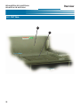
Model: EOF-10-10/FFLT/24/24
Model: EOF-20/FFLT/24/24
Giles Enterprises, Inc.
FOODSERVICE EQUIPMENT
2750 Gunter Park Drive West • Montgomery, AL 36109 USA
Fax: 334.239.4117 • Website: www.gfse.com
Service Hotline (Toll Free): 800.554.4537 (USA & Canada Only)
Form No. 60221 (Release date: 11/99) Revised: 07/15/12; Rev. E)
LIMITED WARRANTY
•
Subject to the terms and conditions of this Limited Warranty as herein stated, all Giles Enterprises,
Inc., Foodservice Equipment and parts purchased new from an authorized Giles Enterprises, Inc.,
representative are warranted as to defects in material or workmanship for a period of 12 months
from the date of installation, provided, however, that with regard to labor costs in connection with
this warranty, see below. All installations must be made by a qualified installing agency in accordance with all applicable codes and/or regulations in the jurisdiction in which installed. Limited warranty coverage is extended to the original owner only and is void if the unit is resold.
•
During the Limited Warranty period, Giles Enterprises, Inc. will replace or recondition, at its factory,
any part or parts of this unit which Giles Enterprises, Inc. inspectors judge defective, provided the
unit has been subjected to normal usage, properly installed, operated and serviced. This Limited
Warranty does not cover cosmetic damage, and damage due to acts of God, accident, misuse, alteration, negligence, abuse of the Giles Foodservice Equipment or the use of unorthodox repair methods. All parts replaced under this Limited Warranty carry only the unexpired term of this Limited
Warranty. Limited Warranty service may be furnished only by an authorized Giles Enterprises, Inc.,
representative.
•
If Limited Warranty service is requested, Giles Enterprises, Inc., will send factory-authorized service representatives to repair, recondition, replace or inspect units of its manufacture with such labor
being rendered without cost to owner for ninety (90) days from the date of installation. Otherwise,
service, including labor and transportation charges or other expenses, in connection with the
removal or installation of any part or parts supplied under this Limited Warranty, are specified on the
original sales contract between the purchaser and the authorized Giles Enterprises, Inc., representative.
•
Giles Enterprises, Inc. reserves the right to change or improve its equipment and parts in any way
without obligation to alter such equipment or parts previously manufactured.
•
Giles Enterprises, Inc. makes no further warranties, express or implied including implied warranties
of merchantability or fitness for a particular purpose, and has no other obligation or liability not
specifically stated herein.
•
Repair or replacement as provided under this limited warranty is the exclusive remedy. Giles
Enterprises, Inc., shall not be liable for any incidental or consequential damages for breach of any
express or implied warranty on this product, except to the extent prohibited by applicable law. Any
implied warranty of merchantability or fitness for a particular purpose on this product is limited in
duration to the duration of this limited warranty.
•
Used Giles Enterprises, Inc., Foodservice Equipment or parts or Giles Enterprises, Inc., Foodservice
Equipment or parts not purchased from an authorized Giles Enterprises, Inc., representative, carry
no warranties, express or implied.
Table Of Contents
Safety
EOF-10-10/FFLT/24, EOF-10-10/FFLT/24/24
EOF-20/FFLT/24/24, EOF-20/FFLT/24/24
. . . . . . . . . . . . . . . . . . . . . . . . . . . . . . . . . . . . . . . . . . . . . . . . . . . . . . . vii
Safety Overview . . . . . . . . . . . . . . . . . . . . . . . . . . . . . . . . . . . . . . . . . . . . . . . . . . . . . . . . . . . . . . . . . . . vii
Specific Safety Precautions . . . . . . . . . . . . . . . . . . . . . . . . . . . . . . . . . . . . . . . . . . . . . . . . . . . . . . . . . . viii
1.
Introduction . . . . . . . . . . . . . . . . . . . . . . . . . . . . . . . . . . . . . . . . . . . . . . 1
1-01.
1-02.
1-03.
1-04.
1-04.1.
1-04.2.
1-04.3.
1-04.4.
1-04.5.
Construction . . . . . . . . . . . . . . . . . . . . . . . . . . . . . . . . . . . . . . . . . . . . . . . . . . . . . . . . . . . . . . 1
Standard Features. . . . . . . . . . . . . . . . . . . . . . . . . . . . . . . . . . . . . . . . . . . . . . . . . . . . . . . . . . 1
Optional Features . . . . . . . . . . . . . . . . . . . . . . . . . . . . . . . . . . . . . . . . . . . . . . . . . . . . . . . . . . 1
Specifications . . . . . . . . . . . . . . . . . . . . . . . . . . . . . . . . . . . . . . . . . . . . . . . . . . . . . . . . . . . . . 2
Overall Dimensions for EOF-10-10/FFLT/24(24) or EOF-20/FFLT/24(24) . . . . . . . . . . . . . . . . . 2
Regulatory Listings . . . . . . . . . . . . . . . . . . . . . . . . . . . . . . . . . . . . . . . . . . . . . . . . . . . . . . . . . 3
Basket Size . . . . . . . . . . . . . . . . . . . . . . . . . . . . . . . . . . . . . . . . . . . . . . . . . . . . . . . . . . . . . . . 3
Vat Size and Capacity . . . . . . . . . . . . . . . . . . . . . . . . . . . . . . . . . . . . . . . . . . . . . . . . . . . . . . . 3
Shipping Specifications (Crated) . . . . . . . . . . . . . . . . . . . . . . . . . . . . . . . . . . . . . . . . . . . . . . . 4
2.
Installation . . . . . . . . . . . . . . . . . . . . . . . . . . . . . . . . . . . . . . . . . . . . . . . 5
2-01.
2-02.
2-03.
2-04.
2-04.1.
2-04.1.
2-04.2.
2-05.
2-05.1.
2-06.
Location . . . . . . . . . . . . . . . . . . . . . . . . . . . . . . . . . . . . . . . . . . . . . . . . . . . . . . . . . . . . . . . . . 5
Unpacking . . . . . . . . . . . . . . . . . . . . . . . . . . . . . . . . . . . . . . . . . . . . . . . . . . . . . . . . . . . . . . . . 6
Shipping Bars . . . . . . . . . . . . . . . . . . . . . . . . . . . . . . . . . . . . . . . . . . . . . . . . . . . . . . . . . . . . . 7
Electrical Requirements . . . . . . . . . . . . . . . . . . . . . . . . . . . . . . . . . . . . . . . . . . . . . . . . . . . . . 8
EOF-10-10 Electrical Specifications . . . . . . . . . . . . . . . . . . . . . . . . . . . . . . . . . . . . . . . . . . . . . 8
EOF-20 Electrical Specifications . . . . . . . . . . . . . . . . . . . . . . . . . . . . . . . . . . . . . . . . . . . . . . . 8
EOF-24 Electrical Specifications . . . . . . . . . . . . . . . . . . . . . . . . . . . . . . . . . . . . . . . . . . . . . . . 9
Electrical Connections . . . . . . . . . . . . . . . . . . . . . . . . . . . . . . . . . . . . . . . . . . . . . . . . . . . . . . 9
Electrical Connections Diagram . . . . . . . . . . . . . . . . . . . . . . . . . . . . . . . . . . . . . . . . . . . . . . 10
Ventilation of Fryer . . . . . . . . . . . . . . . . . . . . . . . . . . . . . . . . . . . . . . . . . . . . . . . . . . . . . . . . 10
3.
Overview . . . . . . . . . . . . . . . . . . . . . . . . . . . . . . . . . . . . . . . . . . . . . . . 11
3-01.
3-02.
3-03.
3-04.
3-05.
3-06.
3-07.
3-08.
3-09.
3-10.
3-11.
3-12.
3-13.
3-14.
3-15.
EOF-10-10 Basket Elevator and Baskets . . . . . . . . . . . . . . . . . . . . . . . . . . . . . . . . . . . . . . . . 12
EOF-10-10 Control Panel . . . . . . . . . . . . . . . . . . . . . . . . . . . . . . . . . . . . . . . . . . . . . . . . . . . . 14
EOF-10-10 Lower Cabinet Area . . . . . . . . . . . . . . . . . . . . . . . . . . . . . . . . . . . . . . . . . . . . . . . 16
EOF-20 Basket Elevator and Baskets . . . . . . . . . . . . . . . . . . . . . . . . . . . . . . . . . . . . . . . . . . 18
EOF-20 Control Panel . . . . . . . . . . . . . . . . . . . . . . . . . . . . . . . . . . . . . . . . . . . . . . . . . . . . . . 20
EOF-20 Lower Cabinet Area . . . . . . . . . . . . . . . . . . . . . . . . . . . . . . . . . . . . . . . . . . . . . . . . . 22
FFLT Table . . . . . . . . . . . . . . . . . . . . . . . . . . . . . . . . . . . . . . . . . . . . . . . . . . . . . . . . . . . . . . . 24
FFLT Control Panel . . . . . . . . . . . . . . . . . . . . . . . . . . . . . . . . . . . . . . . . . . . . . . . . . . . . . . . . 26
FFLT Lower Cabinet Area . . . . . . . . . . . . . . . . . . . . . . . . . . . . . . . . . . . . . . . . . . . . . . . . . . . 28
EOF-24 Basket Hanger and Baskets . . . . . . . . . . . . . . . . . . . . . . . . . . . . . . . . . . . . . . . . . . . 30
EOF-24 Control Panel . . . . . . . . . . . . . . . . . . . . . . . . . . . . . . . . . . . . . . . . . . . . . . . . . . . . . . 32
EOF-24 Lower Cabinet Area . . . . . . . . . . . . . . . . . . . . . . . . . . . . . . . . . . . . . . . . . . . . . . . . . 34
Filter Pan Assembly . . . . . . . . . . . . . . . . . . . . . . . . . . . . . . . . . . . . . . . . . . . . . . . . . . . . . . . 36
Accessories (Included) . . . . . . . . . . . . . . . . . . . . . . . . . . . . . . . . . . . . . . . . . . . . . . . . . . . . . 38
Accessories (Not Included). . . . . . . . . . . . . . . . . . . . . . . . . . . . . . . . . . . . . . . . . . . . . . . . . . 41
iii
EOF-10-10/FFLT/24, EOF-10-10/FFLT/24/24,
EOF-20/FFLT/24, EOF-20/FFLT/24,24
Table Of Contents
4.
Unit Preparation . . . . . . . . . . . . . . . . . . . . . . . . . . . . . . . . . . . . . . . . . 43
4-01.
4-02.
4-03.
4-04.
4-05.
4-06.
Settings before each test . . . . . . . . . . . . . . . . . . . . . . . . . . . . . . . . . . . . . . . . . . . . . . . . . . . 43
Power test . . . . . . . . . . . . . . . . . . . . . . . . . . . . . . . . . . . . . . . . . . . . . . . . . . . . . . . . . . . . . . 45
Heating Element test . . . . . . . . . . . . . . . . . . . . . . . . . . . . . . . . . . . . . . . . . . . . . . . . . . . . . . 46
Filter Pump Test . . . . . . . . . . . . . . . . . . . . . . . . . . . . . . . . . . . . . . . . . . . . . . . . . . . . . . . . . . 47
Perform Boil Out Procedure . . . . . . . . . . . . . . . . . . . . . . . . . . . . . . . . . . . . . . . . . . . . . . . . . 48
Clean Filter Pan. . . . . . . . . . . . . . . . . . . . . . . . . . . . . . . . . . . . . . . . . . . . . . . . . . . . . . . . . . . 48
5.
Fryer Operation . . . . . . . . . . . . . . . . . . . . . . . . . . . . . . . . . . . . . . . . . . 49
5-01.
5-01.1.
5-01.2.
5-01.3.
5-01.4.
5-01.5.
5-01.6.
5-01.7.
5-01.8.
5-02.
5-03.
5-04.
5-05
5-05.1
5-06.
5-07.
Cooking Controller . . . . . . . . . . . . . . . . . . . . . . . . . . . . . . . . . . . . . . . . . . . . . . . . . . . . . . . . 50
Buttons and Functions . . . . . . . . . . . . . . . . . . . . . . . . . . . . . . . . . . . . . . . . . . . . . . . . . . . . . 51
Programming the Cooking Temperature . . . . . . . . . . . . . . . . . . . . . . . . . . . . . . . . . . . . . . . . 52
Programming a Cooking Time. . . . . . . . . . . . . . . . . . . . . . . . . . . . . . . . . . . . . . . . . . . . . . . . 53
Start a cooking time . . . . . . . . . . . . . . . . . . . . . . . . . . . . . . . . . . . . . . . . . . . . . . . . . . . . . . . 54
Cancel the currently running cooking time. . . . . . . . . . . . . . . . . . . . . . . . . . . . . . . . . . . . . . 54
Manually lowering and raising the cooking basket (Basket Elevator Only) . . . . . . . . . . . . . 54
Displaying remaining cooking time. . . . . . . . . . . . . . . . . . . . . . . . . . . . . . . . . . . . . . . . . . . . 55
Displaying the actual temperature of the liquid shortening . . . . . . . . . . . . . . . . . . . . . . . . . 55
Cooking Procedure . . . . . . . . . . . . . . . . . . . . . . . . . . . . . . . . . . . . . . . . . . . . . . . . . . . . . . . . 56
Filtering Liquid Shortening . . . . . . . . . . . . . . . . . . . . . . . . . . . . . . . . . . . . . . . . . . . . . . . . . . 61
Removal of Liquid Shortening . . . . . . . . . . . . . . . . . . . . . . . . . . . . . . . . . . . . . . . . . . . . . . . 64
Using the Optional Renewable Filter Media (SSFS).. . . . . . . . . . . . . . . . . . . . . . . . . . . . . . . 67
Washing the Renewable Filter Media (SSFS). . . . . . . . . . . . . . . . . . . . . . . . . . . . . . . . . . . . 67
Normal Shut-Down . . . . . . . . . . . . . . . . . . . . . . . . . . . . . . . . . . . . . . . . . . . . . . . . . . . . . . . . 68
Emergency Shut-Down. . . . . . . . . . . . . . . . . . . . . . . . . . . . . . . . . . . . . . . . . . . . . . . . . . . . . 68
6.
Cleaning . . . . . . . . . . . . . . . . . . . . . . . . . . . . . . . . . . . . . . . . . . . . . . . . 69
6-01.
6-02.
6-03.
Boil-Out Procedure (Cleaning the Fry Pot) . . . . . . . . . . . . . . . . . . . . . . . . . . . . . . . . . . . . . . 69
Cleaning the Filter Pan and replacing Filter Paper after Boil Out . . . . . . . . . . . . . . . . . . . . . 72
Cleaning the Filter Pan and replacing the Filter Paper daily . . . . . . . . . . . . . . . . . . . . . . . . . 73
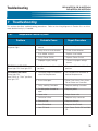
7.
Troubleshooting . . . . . . . . . . . . . . . . . . . . . . . . . . . . . . . . . . . . . . . . . 75
7-01.
7-02.
7-03.
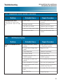
Temperature Control System . . . . . . . . . . . . . . . . . . . . . . . . . . . . . . . . . . . . . . . . . . . . . . . . 75
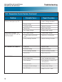
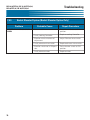
Oil Filtration System . . . . . . . . . . . . . . . . . . . . . . . . . . . . . . . . . . . . . . . . . . . . . . . . . . . . . . . 77
Basket Elevator System (Basket Elevator Option Only) . . . . . . . . . . . . . . . . . . . . . . . . . . . . 78
8.
Parts List . . . . . . . . . . . . . . . . . . . . . . . . . . . . . . . . . . . . . . . . . . . . . . . 79
8–01.
8-02.
8-03.
8-04.
8-05.
8-06.
8-07.
8-08.
Parts Ordering and Service Information . . . . . . . . . . . . . . . . . . . . . . . . . . . . . . . . . . . . . . . . 79
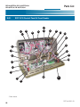
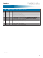
EOF-10-10 Control Panel & Front Header . . . . . . . . . . . . . . . . . . . . . . . . . . . . . . . . . . . . . . . 80
EOF-10-10 Front Lower Cabinet . . . . . . . . . . . . . . . . . . . . . . . . . . . . . . . . . . . . . . . . . . . . . . 82
EOF-10-10 Rear Lower Cabinet . . . . . . . . . . . . . . . . . . . . . . . . . . . . . . . . . . . . . . . . . . . . . . . 84
EOF-20 Control Panel & Front Header . . . . . . . . . . . . . . . . . . . . . . . . . . . . . . . . . . . . . . . . . 86
EOF-20 Front Lower Cabinet. . . . . . . . . . . . . . . . . . . . . . . . . . . . . . . . . . . . . . . . . . . . . . . . . 88
EOF-20 Rear Lower Cabinet . . . . . . . . . . . . . . . . . . . . . . . . . . . . . . . . . . . . . . . . . . . . . . . . . 90
EOF-24 Control Panel & Front Header . . . . . . . . . . . . . . . . . . . . . . . . . . . . . . . . . . . . . . . . . 92
iv
Table Of Contents
8-09.
8-10.
8-11.
8-12.
8-13.
EOF-10-10/FFLT/24, EOF-10-10/FFLT/24/24
EOF-20/FFLT/24/24, EOF-20/FFLT/24/24
EOF-24 Front Lower Cabinet. . . . . . . . . . . . . . . . . . . . . . . . . . . . . . . . . . . . . . . . . . . . . . . . . 94
EOF-24 Rear Lower Cabinet . . . . . . . . . . . . . . . . . . . . . . . . . . . . . . . . . . . . . . . . . . . . . . . . . 96
FFLT Front. . . . . . . . . . . . . . . . . . . . . . . . . . . . . . . . . . . . . . . . . . . . . . . . . . . . . . . . . . . . . . . 98
FFLT Rear . . . . . . . . . . . . . . . . . . . . . . . . . . . . . . . . . . . . . . . . . . . . . . . . . . . . . . . . . . . . . . 100
Filter Pan . . . . . . . . . . . . . . . . . . . . . . . . . . . . . . . . . . . . . . . . . . . . . . . . . . . . . . . . . . . . . . . 102
v
EOF-10-10/FFLT/24, EOF-10-10/FFLT/24/24,
EOF-20/FFLT/24, EOF-20/FFLT/24,24
Notes:
vi
Table Of Contents
EOF-10-10/FFLT/24, EOF-10-10/FFLT/24/24
EOF-20/FFLT/24, EOF-20/FFLT/24/24
Safety
Safety
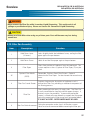
Safety Overview
The instructions contained in this manual have been prepared to aid you in learning the proper procedures
for installing and servicing your unit.
Throughout this manual, safety precautions are identified through the use of the safety alert symbol and
three signal words: DANGER, WARNING, and CAUTION. All safety alert information precedes the
step(s) to which they apply. Suggested, recommended, or other noteworthy information is identified
through the use of NOTES. Additionally, certain words are used to indicate a specific meaning or to add
emphasis.
The following words are used as indicated throughout the manual:
Shall: understood to be mandatory.
Should: understood to be advisory.
May: understood to be permissive.
Will: indicates a future event/condition to occur.
! or !
(Safety Alert Symbol)
Used in conjunction with signal words (DANGER, WARNING, or CAUTION) to alert you of potential personal injury hazards, immediately preceding precautionary measures that pertain to subsequent step(s).
Obey all safety messages that follow these symbols to avoid possible injury or death. Failure to adhere to
safety precautions identified by the safety alert symbol may also void the warranty.
!
DANGER
• Indicates an imminently hazardous situation which, if not avoided, will result in death or serious injury.
Use of this is limited to the most extreme situations.
! WARNING
• Indicates a potentially hazardous situation which, if not avoided, could result in death or serious injury.
! CAUTION
• Indicates a potentially hazardous situation which, if not avoided, may result in minor or moderate injury.
Also used to alert against unsafe practices.
CAUTION
• When used without the safety alert symbol, CAUTION indicates a potentially hazardous situation
which, if not avoided, may result in equipment/property damage, and void the warranty.
NOTE:
• Identifies suggested, recommended, or other noteworthy information.
vii
EOF-10-10/FFLT/24, EOF-10-10/FFLT/24/24,
EOF-20/FFLT/24, EOF-20/FFLT/24/24
Safety
Specific Safety Precautions
For your safety, please observe the following precautions when operating or servicing this unit. Read the
following important safety information to avoid personal injury and/or damage to the equipment.
!
DANGER
• Turn off the unit and unplug the power cord before cleaning or performing maintenance.
• DO NOT hose down the unit’s interior or exterior with water.
• Failure to comply with these DANGER notices will result in death or serious injury, equipment/property damage,
and void the warranty.
! WARNING
• Consult a qualified electrician to ensure that:
•• all electrical specifications and codes are met.
•• circuit breakers and wiring are of sufficient rating and gauge.
• The unit must be properly grounded and all electrical specifications must be met during installation.
• Improper installation, adjustment, alteration, service or maintenance could result in death or serious injury, equipment/property damage, and void the warranty.
• DO NOT use or store gasoline or other flammable liquids or vapors in the vicinity of this or any other electrical
appliance!
• Failure to comply with WARNING notices could result in death or serious injury and equipment/property damage
and void the warranty.
! CAUTION
• The unit must remain in the upright (vertical) position.
• Exercise care when removing the wooden crate from around the unit.
• DO NOT operate the unit unless you fully understand the components and their intended functions (see Section
3).
• The unit and its parts are HOT!
Exercise caution when operating, loading/unloading food, cleaning or servicing.
Wearing of thermal oven mitts is recommended.
• Failure to comply with CAUTION notices may result in minor or moderate injury, equipment/property damage,
and void the warranty.
viii
EOF-10-10/FFLT/24, EOF-10-10/FFLT/24/24
EOF-20/FFLT/24, EOF-20/FFLT/24/24
Safety
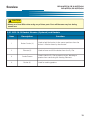
! CAUTION
• Food products must be maintained at a temperature of 150°F (65.5°C) minimum or in accordance with local or
state health regulations.
•
Fryers must be adequately and properly grounded. Improper grounding may result in electrical shock.
Always refer to your local electrical code to ensure proper grounding of this or any other electrical equipment. Always consult with an electrician or other qualified service person to ensure breakers and wiring are
of sufficient rating and gauge for the equipment being operated.
• Giles Electric Fryers are available from the factory wired for various voltages, phase and hertz. Check the rating
plate on the front of the fryer to determine the correct power supply.
• Ensure the fry kettle is positioned in a secure, safe location with the casters in the locked position.
• Consult an electrician to ensure all electrical specifications have been met and the unit is properly grounded. The
wiring diagrams contained in this manual should aid your electrician in the installation of your fryer.
• Due to the high temperature of shortening in your fryer during cooking, it is extremely important the user exercise caution in the operation of this equipment to avoid personal injury.
• Before attempting to operate the unit, refer to Section 3 to familiarize yourself with the various control functions.
• Be careful not to puncture the filter paper when using the brush to unclog the Drain Valve.
• Allow the unit to cool down a minimum of 15 minutes before cleaning or servicing.
CAUTION
• The electronic components of the Control Panel are impact-sensitive. Exercise care around the Control Panel to
maintain proper operation.
• DO NOT install the unit next to combustible walls and materials. Failure to maintain safe distances may result in
fire.
• During cleaning of the unit:
••
••
••
••
DO
DO
DO
DO
NOT
NOT
NOT
NOT
steam clean.
use products containing chlorine.
use abrasive products, steel wool or scouring pads.
use oven cleaner.
• Failure to comply with these CAUTION notices may result in equipment/property damage and void the warranty.
• Failure to comply with these CAUTION notices may violate local health codes.
• DO NOT Modify, Alter or Add Attachments to this Equipment!
ix
EOF-10-10/FFLT/24, EOF-10-10/FFLT/24/24,
EOF-20/FFLT/24, EOF-20/FFLT/24/24
Safety
NOTE:
• If the crate in which the unit is shipped is damaged upon receipt, immediately inspect the unit and notify the carrier of any damage to the unit.
• To aid the electrician, an electrical wiring diagram is contained in this manual. Refer to the wiring diagram during
installation or servicing.
• Comply with all appropriate state and/or local heath regulations regarding the cleaning and sanitation of equipment.
x
Introduction
1.
EOF-10-10/FFLT/24, EOF-10-10/FFLT/24/24
EOF-20/FFLT/24, EOF-20/FFLT/24/24
Introduction
Congratulations on the purchase of your new Giles equipment, Model EOF-10-10/FFLT/24/24 or
EOF-10-10/FFLT/24, EOF-20/FFLT/24/24 or EOF-20/FFLT/24, manufactured by Giles Enterprises, Inc.,
Montgomery, Alabama (USA), hereafter referred to as "Giles". Every unit is thoroughly inspected and tested prior to shipment. Proper care and maintenance will ensure years of trouble-free service.
To help protect your investment in this state-of-the-art cooking equipment, we recommend you take a few
moments to familiarize yourself with the installation, cleaning and maintenance procedures contained in this
manual. Adherence to these recommended procedures minimizes the potential for costly “Down-Time” and
equipment repairs. Please retain this manual for future reference.
1-01. Construction
Model EOF-10-10/FFLT/24, EOF-10-10/FFLT/24/24, EOF-20/FFLT/24/24 and EOF-20/FFLT/24/24, exterior and
fry vats are constructed of stainless steel.
1-02. Standard Features
Temperature Controller -used to control the temperature of the cooking oil and the cooking time.
Oil Filtration System -used to extend the life of cooking oil.
FFLT (Fried Food Landing Table) -used as a convenient location to place cooked product.
1-03. Optional Features
Automatic Basket Lift -used to automatically lift cooked product from hot cooking oil at the end of the
cooking cycle.
1
EOF-10-10/FFLT/24, EOF-10-10/FFLT/24/24,
EOF-20/FFLT/24, EOF-20/FFLT/24/24
Introduction
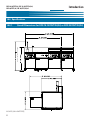
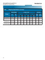
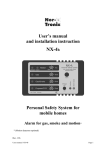
1-04. Specifications
1-04.1.
Overall Dimensions for EOF-10-10/FFLT/24(24) or EOF-20/FFLT/24(24)
EOF-10-10/FFLT/24/24 or EOF-20/FFLT/24/24
BASKET LIFT IN UP POSITION
EOF-10-10/FFLT/24 or EOF-20/FFLT/24
INCHES [MILLIMETERS]
2
EOF-10-10/FFLT/24, EOF-10-10/FFLT/24/24
EOF-20/FFLT/24, EOF-20/FFLT/24/24
Introduction
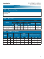
1-04.2.
Regulatory Listings
UL (US and Canada)
UL Sanitation
1-04.3.
Basket Size
Basket Size
Model
Height
Width
Length
Volume
cubic inch
cubic meter
139.7
811
0.005
127
1176
0.019
in
mm
in
mm
in
mm
EOF-10 or EOF-20
9.00
228.6
18.50
469.9
5.5
EOF-24
11.00
279.4
22.75
577.85
5.0
1-04.4.
Vat Size and Capacity
Width
(Inside)
Length
(Inside)
Model
Height
(Top of element to oil
level line
Liquid Shortening Capacity
(Bottom of Vat to Oil level)
In
mm
In
mm
In
mm
Lbs
Kg
Gal
Lt
EOF-10
20
508
10
254
4 1/2
114
55
25
8
29.5
EOF-20
20
508
20
508
4 1/2
114
110
50
16
59
EOF-24
24
610
24
610
4 1/2
114
160
73
23
86
3
EOF-10-10/FFLT/24, EOF-10-10/FFLT/24/24,
EOF-20/FFLT/24, EOF-20/FFLT/24/24
1-04.5.
Introduction
Shipping Specifications (Crated)
Crated Size
Net Weight
Model
Length
Lbs
Volume
Width
Height
Kg
In
mm
In
mm
In
mm
Cubic
Feet
Cubic
Meters
EOF-10-10/FFLT/24
1069
485
108
2743
50
1270
61
1549
193.75
5.5
EOF-10-10/FFLT/24/24
1197
543
108
2743
50
1270
61
1549
193.75
5.5
EOF-20/FFLT/24
1069
485
108
2743
50
1270
61
1549
193.75
5.5
EOF-20/FFLT/24/24
1197
543
108
2743
50
1270
61
1549
193.75
5.5
4
Installation
EOF-10-10/FFLT/24, EOF-10-10/FFLT/24/24
EOF-20/FFLT/24, EOF-20/FFLT/24/24
2. Installation
This section provides a summary of the procedures necessary for proper installation of your new unit. To prevent personal injury or equipment damage, please ensure the following steps are taken.
2-01. Location
! CAUTION
• DO NOT MODIFY, ALTER OR ADD ATTACHMENTS TO THIS EQUIPMENT
1.
Keep the appliance and surrounding area free and clear from combustible materials. {(3")(7.6cm) for
Fryer.}
2.
Please note wiring diagrams for this appliance are located in the rear of this manual. Ensure the
wiring diagram corresponds with the model being operated.
3.
Please ensure this appliance is electrically grounded in accordance with local codes, or in the absence
of local codes, with the National Electrical Code, ANSI/NFPA NO. 70-1999.
4.
Please provide adequate room for servicing and proper operation of this appliance. Also, provide
adequate ventilation in the operating area where necessary.
5.
Always consult with an electrician or other qualified individual prior to installation.
6.
Ensure voltage and amperage supplied to the unit are as specified on the fryer’s rating plate.
7.
Make sure this unit is in a secure position and will not move. Locking casters are supplied on this
unit--use them!
8.
This appliance is to be installed, used and maintained in accordance with the Standard for Ventilation
Control, and Fire Protection of Commercial Cooking Operations, NFPA 96-1994.
Compliance with the above steps will help to ensure safe and proper installation of your fryer. If you have any
questions concerning these procedures, contact your local Giles distributor or other qualified service person.
5
EOF-10-10/FFLT/24, EOF-10-10/FFLT/24/24,
EOF-20/FFLT/24, EOF-20/FFLT/24/24
Installation
2-02. Unpacking
Your Giles Fryer may arrive enclosed by a wooden crate. The Fryer is secured to a wooden platform by means
of high-tensile strength strapping.
! CAUTION
• Exercise care when lifting or moving the unit.
• Exercise care when removing the wooden crate from around the unit.
• Failure to comply with these CAUTION notices may result in minor or moderate injury, equipment/property damage, and void the warranty.
NOTE:
• If crate is damaged, immediately inspect the unit and notify the carrier of any damage to the
unit.
1. Carefully cut and remove the plastic shipping wrap and the strapping mentioned above.
2. Use pliers to loosen wire hooks which secure the wooden crate around the fryer. Remove the wooden crate.
3. Carefully remove the fryer from the shipping platform. Your new fryer is extremely heavy, the uncrated weight for the EOF-10-10/FFLT/24 and the EOF-20/FFLT/24 is 769 lbs (349 kg); the EOF-1010/FFLT/24/24 and EOF-20/FFLT/24/24 is 897 lbs (407 kg), only use a fork lift when lifting this equipment, refer to 2-03.
6
Installation
EOF-10-10/FFLT/24, EOF-10-10/FFLT/24/24
EOF-20/FFLT/24, EOF-20/FFLT/24/24
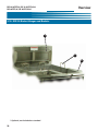
2-03. Shipping Bars
Reinforcement bars have been attached to the framework, at both the front and rear of the fryer bank.
These bars are provided as a stabilizing reinforcement for lifting the unit and during installation. Please
note the following:
1. The bars must remain in place until the fryer is positioned in the designated final position.
2. Open or remove front doors before placing forks underneath the unit.
3. The bars are designed to be used as a lifting point for fork trucks or other type lifting devices.
! CAUTION
• Caution must be used whenever attempting to lift any fryer or placing forks for lifting to insure
that components on the fryer are not hit by the forks or damaged due to lifting.
4. After the banked unit is in the final position, the front bar must be removed to permit installation and
proper operation of the fryer Filter Pan.
NOTE:
• The Front Bar must be removed to allow the installation of the Filter Pan.
5. The rear bar is intended to remain in place and will not affect fryer operation.
6. Remove the front bar by removing all the screws fastening the bar to the fryer frame. Note that the
bar is fastened to the fryer at all vertical uprights.
7.
Once the screws are removed, the bar can be removed from the fryer.
8. Install the screws that are included with the shipping documents, these screws are designed to
replace the screws removed when removing the shipping bar.
9. Close or reinstall the unit's front doors.
10. Once the front bar is removed, then please follow the instructions provided in the operation manual for
the remaining installation and operation of the equipment.
NOTE:
• Giles is not liable for damage to a unit caused by the improper use of forklifts or other handling
equipment, or by premature removal of the reinforcing bars. The bars must remain in place until
the fryer has been located in the designated final operating position. Failure to follow these
instructions could void the warranty. Giles is not liable for injuries incurred during installation of
this equipment. Installation of this equipment is the sole responsibility of the purchaser.
7
EOF-10-10/FFLT/24, EOF-10-10/FFLT/24/24,
EOF-20/FFLT/24, EOF-20/FFLT/24/24
Installation
2-04. Electrical Requirements
! CAUTION
• Fryers must be adequately and properly grounded.
Improper grounding may result in electrical
shock. Always refer to your local electrical code to ensure proper grounding of this or any other
electrical equipment. Always consult with an electrician or other qualified service person to ensure
breakers and wiring are of sufficient rating and gauge for the equipment being operated.
The EOF-10-10, EOF-20 and EOF-24 are available from the factory in the voltages and phases listed below.
Check the rating plate on the rear of the fryer to determine the correct power supply.
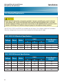
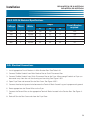
2-04.1. EOF-10-10 Electrical Specifications
Voltage
Phase
Amps
L1
L2
L3
Circuit Breaker
required
Watts
208
3
24,000
68
66
68
80
240
3
24,000
59
57
59
75
480
3
24,000
31
29
31
50
2-04.1. EOF-20 Electrical Specifications
Voltage
8
Phase
Amps
L1
L2
L3
Circuit Breaker
required
Watts
208
1
24,000
115
115
---
150
208
3
24,000
72
46
72
80
240
1
24,000
100
100
---
125
240
3
24,000
68
44
68
75
480
3
24,000
34
22
34
50
EOF-10-10/FFLT/24, EOF-10-10/FFLT/24/24
EOF-20/FFLT/24, EOF-20/FFLT/24/24
Installation
2-04.2. EOF-24 Electrical Specifications
Voltage
Phase
Amps
L1
L2
L3
Circuit Breaker
required
Watts
208
1
30,000
144
144
---
200
208
3
30,000
72
92
72
100
240
1
30,000
125
125
---
150
240
3
30,000
68
88
68
100
480
3
30,000
34
44
34
50
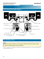
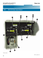
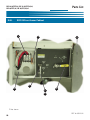
2-05. Electrical Connections
1. Install appropriate Circuit Breakers in Main Breaker Box! See Table 2-04.
2. Connect Flexible Conduit from Main Breaker Box to Quick Disconnect Box.
3. Connect Flexible Conduit from Quick Disconnect Box to the Fryer. Allow enough Conduit so Fryer can
be moved away from the wall for cleaning and servicing. See Figure 2-05.1.
4. Open Fryer Door and remove Service Box Cover. See Figure 2-05.1.
5. Connect the electrical ground wire between the Terminal Block Ground Lug and a proper earth ground.
6. Route appropriate size Power Wires to the Fryer.
7.
Connect the Power Wires to the appropriate Terminal Blocks located in the Service Box. See Figure 204.1.
8. Reinstall Service Box Cover and close the Fryer Door.
9
EOF-10-10/FFLT/24, EOF-10-10/FFLT/24/24,
EOF-20/FFLT/24, EOF-20/FFLT/24/24
Installation
2-05.1. Electrical Connections Diagram
Flexible Conduit
Flexible Conduit
Service Box
Terminal Blocks
Service Box Cover
Terminal Blocks
Power Wires from QuickDisconnect Box
Service Box Cover
Ground Lug
Power Wires from QuickDisconnect Box
Service Box
2-06. Ventilation of Fryer
NOTE:
•Guidelines for proper ventilation system requirements differ from location to location. Always
consult with local authorities to ensure compliance.
Consult a professional ventilation or heating and air conditioning company for assistance in designing a
Ventilation hood for this unit.
10
EOF-10-10/FFLT/24, EOF-10-10/FFLT/24/24
EOF-20/FFLT/24, EOF-20/FFLT/24/24
Overview
3. Overview
The following section provides a brief overview of the components, functions, and accessories of the unit.
Please review this section carefully before proceeding any further.
EOF-20 Baskets and Basket Lift
(Shown) Figure 3-04.
or
EOF-10-10 Baskets and Basket Lift
Figure 3-01.
Landing Table
Figure 3-04.
FFLT Control Panel
Figure 3-05.
EOF-24 Baskets
and Basket
Hanger
Figure 3-07.
EOF-20 Control
Panel
Figure 3-05.
(Shown)
or
EOF-10-10 Control
Panel
Figure 3-02.
EOF-20 Lower Cabinet Area
(Shown) Figure 3-06.
or
EOF-10-10 Lower Cabinet Area
Figure 3-03.
Filter Pan Assembly
Figure 3-10.
EOF-24 Lower
Cabinet Area
Figure 3-09.
EOF-24 Control
Panel
Figure 3-08.
FFLT Lower Cabinet
Area
Figure 3-06.
11
EOF-10-10/FFLT/24, EOF-10-10/FFLT/24/24,
EOF-20/FFLT/24, EOF-20/FFLT/24/24
Overview
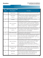
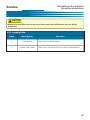
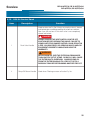
3-01. EOF-10-10 Basket Elevator and Baskets
2
Left Vat
Left Vat
1
Right Vat
1
Right Vat
2
3
Left Vat
Left Vat
3
4
4
12
Right Vat
Right Vat
EOF-10-10/FFLT/24, EOF-10-10/FFLT/24/24
EOF-20/FFLT/24, EOF-20/FFLT/24/24
Overview
! CAUTION
• Always use Oven Mitts when using any of these parts. Parts will become very hot during
normal use.
3-01. EOF-10-10 Basket Elevator (Optional) and Baskets
Item
Description
1
Basket Carrier (2)
2
Elevator (2)
3
Crumb Screen
4
Basket (2)
Function
Used to hold the basket in the correct position when the
basket is lifted or lower by the elevator.
Used to lower and lift the basket from the Fry Pot.
Used inside the Fry Pot to prevent excess breading or
product from contacting the Heating Elements.
Used for cooking product.
13
EOF-10-10/FFLT/24, EOF-10-10/FFLT/24/24,
EOF-20/FFLT/24, EOF-20/FFLT/24/24
Overview
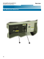
3-02. EOF-10-10 Control Panel
4
3
8
9
5
10
2
6
1
7
14
EOF-10-10/FFLT/24, EOF-10-10/FFLT/24/24
EOF-20/FFLT/24, EOF-20/FFLT/24/24
Overview
3-02. EOF-10-10 Control Panel
Item
Description
1
Power Switch
Heat Switch
2
(Left Vat)
3
Controller
High-Limit Indicator
4
(Left Vat)
Heat Indicator Light
5
(Left Vat)
6
7
Power Indicator Light
Elevator Lift Switch
High-Limit Indicator
8
(Right Vat)
Heat Indicator Light
9
(Right Vat)
Heat Switch
10
(Right Vat)
Function
The Power Switch is used to turn power ON or OFF to the
unit.
The Heat Switch is used to turn power to elements ON and
OFF. Place the Heat Switch in the OFF position when
programming the controller or shutting down the unit. Place
in ON position when ready to heat the oil.
The Electronic Controller is used for setting a cooking
temperature and cooking times.
The Red High-Limit Light indicates an alarm condition. It is
illuminated when power is shut-off to the heating elements
by the overheat safety shutdown control circuit. Should this
light come on during operation, refer to the Troubleshooting,
Section 7, of this manual. COOKING ACTIVITIES SHOULD
BE DISCONTINUED UNTIL CAUSE IS DETERMINED!
The Orange Heat Indicator Light is illuminated when the
Heat Switch is in the ON position and the heating elements
are energized. The light is off during intervals when oil is at
setpoint and elements are de-energized.
The Green Power Light is illuminated whenever the fryer’s
Power Switch is in the ON position.
The Elevator Switch is used activate or deactivate the Basket
Lifts. If the switch is ON the Lift will lower when a cooking
cycle starts and rise when a cooking cycle ends. If the
switch is OFF the Basket Lifts will not operate. (This switch
controls both left and right basket lifts)
The Red High-Limit Light indicates an alarm condition. It is
illuminated when power is shut-off to the heating elements
by the overheat safety shutdown control circuit. Should
this light come on during operation, refer to the
Troubleshooting, Section 7, of this manual. COOKING
ACTIVITIES SHOULD BE DISCONTINUED UNTIL CAUSE IS
DETERMINED!
The Orange Heat Indicator Light is illuminated when the
Heat Switch is in the ON position and the heating elements
are energized. The light is off during intervals when oil is at
setpoint and elements are de-energized.
The Heat Switch is used to turn power to elements ON and
OFF. Place the Heat Switch in the OFF position when
programming the controller or shutting down the unit.
Place in ON position when ready to heat the oil.
15
EOF-10-10/FFLT/24, EOF-10-10/FFLT/24/24,
EOF-20/FFLT/24, EOF-20/FFLT/24/24
Overview
3-03. EOF-10-10 Lower Cabinet Area
1
2 Left Vat
2
1
16
Left Vat
Right Vat
Right Vat
EOF-10-10/FFLT/24, EOF-10-10/FFLT/24/24
EOF-20/FFLT/24, EOF-20/FFLT/24/24
Overview
3-03. EOF-10-10 Lower Cabinet Area
Item
Description
Function
Used to drain the Fry Pot. Always ensure the Handle is
closed and locked prior to adding cooking oil or boil out
solution. Your fryer will not heat if this Drain Valve Handle is
not completely closed and locked.
!
1
Drain Valve Handle
DANGER
ALWAYS ENSURE THE HEAT SWITCH IS IN THE OFF
POSITION BEFORE OPENING THIS VALVE. FAILURE TO
COMPLY WITH THIS DANGER NOTICE COULD RESULT
IN A FIRE, CAUSING DEATH OR SERIOUS INJURY
AND/OR EQUIPMENT/PROPERTY DAMAGE AND VOID
THE WARRANTY.
! WARNING
NEVER DRAIN OIL INTO THE FILTER PAN FROM MORE
THAN ONE FRY POT AT A TIME. DOING SO WILL
CAUSE THE FILTER PAN TO OVERFLOW. ALWAYS PUMP
OIL FROM THE FILTER PAN BACK TO A FRY POT OR TO A
DISPOSAL TANK BEFORE DRAINING ANOTHER FRY POT.
2
Pump Oil Return Handle
Used when Filtering to return oil to the Fry Vat.
17
EOF-10-10/FFLT/24, EOF-10-10/FFLT/24/24,
EOF-20/FFLT/24, EOF-20/FFLT/24/24
Overview
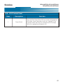
3-04. EOF-20 Basket Elevator and Baskets
1
*2
4
3
18
EOF-10-10/FFLT/24, EOF-10-10/FFLT/24/24
EOF-20/FFLT/24, EOF-20/FFLT/24/24
Overview
! CAUTION
• Always use Oven Mitts when using any of these parts. Parts will become very hot during
normal use.
3-04. Basket Elevator (Optional) and Baskets
Item
Description
1
Basket Carrier (2)
2
Elevator (2)
3
Crumb Screen
4
Basket (2)
Function
Used to hold the basket in the correct position when the
basket is lifted or lower by the elevator.
LowerS and lifts basket from the Fry Pot.
Positioned just above elements to prevent excessive
breading or product crumbs from accumulating near the
Heating Elements.
Used for cooking product.
19
EOF-10-10/FFLT/24, EOF-10-10/FFLT/24/24,
EOF-20/FFLT/24, EOF-20/FFLT/24/24
Overview
3-05. EOF-20 Control Panel
3
2
6
5
1
4
7
20
EOF-10-10/FFLT/24, EOF-10-10/FFLT/24/24
EOF-20/FFLT/24, EOF-20/FFLT/24/24
Overview
3-05. EOF-20 Control Panel
Item
Description
1
Power Switch
2
Heat Switch
3
Controller
Function
The Power Switch is used to turn power ON or OFF to the
unit.
The Heat Switch is used to turn power to elements ON and
OFF. Place the Heat Switch in the OFF position when
programming the controller or shutting down the unit. Place
in ON position when ready to heat the oil.
The Electronic Controller is used for setting a cooking
temperature and cooking times.
High-Limit Indicator
The Red High-Limit Light indicates an alarm condition. It is
illuminated when power is shut-off to the heating elements
by the overheat safety shutdown control circuit. Should this
light come on during operation, refer to the Troubleshooting,
Section 7, of this manual. COOKING ACTIVITIES SHOULD
BE DISCONTINUED UNTIL CAUSE IS DETERMINED!
5
Heat Indicator Light
The Orange Heat Indicator Light is illuminated when the
Heat Switch is in the ON position and the heating elements
are energized. The light is off during intervals when oil is at
setpoint and elements are de-energized.
6
Power Indicator Light
The Green Power Light is illuminated whenever the fryer’s
Power Switch is in the ON position.
4
7
Elevator Switch
The Elevator Switch is used activate or deactivate the Basket
Lifts. If the switch is ON the Lift will lower when a cooking
cycle starts and rise when a cooking cycle ends. If the
switch is OFF the Basket Lifts will not operate. (This switch
controls both left and right basket lifts)
21
EOF-10-10/FFLT/24, EOF-10-10/FFLT/24/24,
EOF-20/FFLT/24, EOF-20/FFLT/24/24
Overview
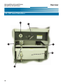
3-06. EOF-20 Lower Cabinet Area
1
2
22
EOF-10-10/FFLT/24, EOF-10-10/FFLT/24/24
EOF-20/FFLT/24, EOF-20/FFLT/24/24
Overview
3-06. EOF-20 Lower Cabinet Area
Item
Description
Function
Used to drain the Fry Pot. Always ensure the Handle is
closed and locked prior to adding cooking oil or boil out
solution. Your fryer will not heat if this Drain Valve Handle is
not completely closed and locked.
!
1
Drain Valve Handle
DANGER
ALWAYS ENSURE THE HEAT SWITCH IS IN THE OFF
POSITION BEFORE OPENING THIS VALVE. FAILURE TO
COMPLY WITH THIS DANGER NOTICE COULD RESULT
IN A FIRE, CAUSING DEATH OR SERIOUS INJURY
AND/OR EQUIPMENT/PROPERTY DAMAGE AND VOID
THE WARRANTY.
! WARNING
NEVER DRAIN OIL INTO THE FILTER PAN FROM MORE
THAN ONE FRY POT AT A TIME. DOING SO WILL
CAUSE THE FILTER PAN TO OVERFLOW. ALWAYS PUMP
OIL FROM THE FILTER PAN BACK TO A FRY POT OR TO A
DISPOSAL TANK BEFORE DRAINING ANOTHER FRY POT.
2
Pump Oil Return Handle
Used when Filtering to return oil to the Fry Vat.
23
EOF-10-10/FFLT/24, EOF-10-10/FFLT/24/24,
EOF-20/FFLT/24, EOF-20/FFLT/24/24
Overview
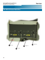
3-07. FFLT Table
1
2
24
EOF-10-10/FFLT/24, EOF-10-10/FFLT/24/24
EOF-20/FFLT/24, EOF-20/FFLT/24/24
Overview
! CAUTION
• Always use Oven Mitts when using any of these parts. Parts will become very hot during
normal use.
3-07. Landing Table
Item
Description
1
Landing Table
2
Landing Table Screen
Function
Dump area for cooked product.
Allow excess oil to drain from the freshly cooked product.
25
EOF-10-10/FFLT/24, EOF-10-10/FFLT/24/24,
EOF-20/FFLT/24, EOF-20/FFLT/24/24
Overview
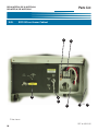
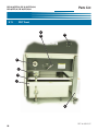
3-08. FFLT Control Panel
1
26
EOF-10-10/FFLT/24, EOF-10-10/FFLT/24/24
EOF-20/FFLT/24, EOF-20/FFLT/24/24
Overview
3-08. FFLT Control Panel
Item
1
Description
Function
Pump Switch
Turns the Filter Pump ON or OFF to circulate oil through the
oil filtration system and return it back to a selected Fry Vat,
or pump oil from the Filter Pan, through the Oil Discharge
Hose to an appropriate oil disposal unit.
27
EOF-10-10/FFLT/24, EOF-10-10/FFLT/24/24,
EOF-20/FFLT/24, EOF-20/FFLT/24/24
Overview
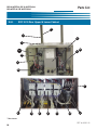
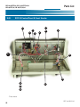
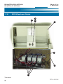
3-09. FFLT Lower Cabinet Area
2
1
3
5
6
4
28
EOF-10-10/FFLT/24, EOF-10-10/FFLT/24/24
EOF-20/FFLT/24, EOF-20/FFLT/24/24
Overview
! WARNING
• Never remove the Filter Pan while it contains Liquid Shortening.
This could result in oil
spillage or possible burn injury. Please see Section 5-4. Removal of Liquid Shortening.
! CAUTION
• Always use Oven Mitts when handling any of these parts.
Parts become very hot during
normal use.
• Never drain Boil Out Solution into the Filter Pan.
Boil Out Solution is corrosive and will
damage the Filter Pan, Filter Pan components and Filter Pump. See Section 6-1. Boil Out
3-09. FFLT Lower Cabinet Area
Item
Description
Function
1
Diverter Valve Handle
Used to direct pumped cooking oil from the Filter Pan to the
Fry Pot or to the Cooking Oil Discharge Hose.
2
Quick Disconnect for
Oil Discharge Wand
Connection fitting for the Oil Discharge Hose when removing
oil from the fryer.
3
Quick Disconnect for
Filter Pan Hose
Fitting for connecting the Filter Pan quick-disconnect hose to
the fryer’s oil filtration system.
4
Filter Pan Quick
Disconnect Hose
See Section 3-8.
5
Filter Pan Cover
Helps prevent possibility of foreign material contamination of
cooking oil during filtering operations.
6
Filter Pan
See Section 3-8.
29
EOF-10-10/FFLT/24, EOF-10-10/FFLT/24/24,
EOF-20/FFLT/24, EOF-20/FFLT/24/24
Overview
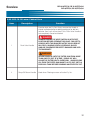
3-10. EOF-24 Basket Hanger and Baskets
1
2
3*
* Optional, not included as standard
30
EOF-10-10/FFLT/24, EOF-10-10/FFLT/24/24
EOF-20/FFLT/24, EOF-20/FFLT/24/24
Overview
! CAUTION
• Always use Oven Mitts when using any of these parts. Parts will become very hot during
normal use.
3-10. EOF-24 Basket Hanger and Baskets
Item
Description
Function
1
Basket Hanger
Used to hold basket(s) allowing excess oil to drain from
cooked product.
2
Crumb Screen
Positioned just above elements to prevent excessive
breading or product crumbs from accumulating near the
Heating Elements.
3
Basket (2)
Used for cooking product. (Optional item, not included as
standard)
31
EOF-10-10/FFLT/24, EOF-10-10/FFLT/24/24,
EOF-20/FFLT/24, EOF-20/FFLT/24/24
Overview
3-11. EOF-24 Control Panel
3
6
2
5
4
1
32
EOF-10-10/FFLT/24, EOF-10-10/FFLT/24/24
EOF-20/FFLT/24, EOF-20/FFLT/24/24
Overview
3-11.
EOF-24 Control Panel
Item
Description
1
Power Switch
2
Heat Switch
3
Controller
Function
The Power Switch is used to turn power ON or OFF to the
unit.
The Heat Switch is used to turn power to elements ON and
OFF. Place the Heat Switch in the OFF position when
programming the controller or shutting down the unit. Place
in ON position when ready to heat the oil.
The Electronic Controller is used for setting a cooking
temperature and cooking times.
High-Limit Indicator
The Red High-Limit Light indicates an alarm condition. It is
illuminated when power is shut-off to the heating elements
by the overheat safety shutdown control circuit. Should this
light come on during operation, refer to the Troubleshooting,
Section 7, of this manual. COOKING ACTIVITIES SHOULD
BE DISCONTINUED UNTIL CAUSE IS DETERMINED!
5
Heat Indicator Light
The Orange Heat Indicator Light is illuminated when the
Heat Switch is in the ON position and the heating elements
are energized. The light is off during intervals when oil is at
setpoint and elements are de-energized.
6
Power Indicator Light
4
The Green Power Light is on whenever the fryer’s Power
Switch is in the ON position.
33
EOF-10-10/FFLT/24, EOF-10-10/FFLT/24/24,
EOF-20/FFLT/24, EOF-20/FFLT/24/24
Overview
3-12. EOF-24 Lower Cabinet Area
2
34
1
EOF-10-10/FFLT/24, EOF-10-10/FFLT/24/24
EOF-20/FFLT/24, EOF-20/FFLT/24/24
Overview
3-12. EOF-24 Control Panel
Item
Description
Function
Used to drain the Fry Pot. Always ensure the valve is closed
and locked prior to adding cooking oil or boil out solution.
Your fryer will not heat if this drain valve is not completely
closed and locked.
!
1
Drain Valve Handle
DANGER
ALWAYS ENSURE THE HEAT SWITCH IS IN THE OFF
POSITION BEFORE OPENING THIS VALVE. FAILURE TO
COMPLY WITH THIS DANGER NOTICE COULD RESULT IN
A FIRE, CAUSING DEATH OR SERIOUS INJURY AND/OR
EQUIPMENT/PROPERTY DAMAGE AND VOID THE
WARRANTY.
! WARNING
NEVER DRAIN OIL INTO THE FILTER PAN FROM MORE
THAN ONE FRY POT AT A TIME. DOING SO WILL CAUSE
THE FILTER PAN TO OVERFLOW. ALWAYS PUMP OIL
FROM THE FILTER PAN BACK TO A FRY POT OR TO A
DISPOSAL TANK BEFORE DRAINING ANOTHER FRY POT.
2
Pump Oil Return Handle
Used when Filtering to return oil to the Fry Vat.
35
EOF-10-10/FFLT/24, EOF-10-10/FFLT/24/24,
EOF-20/FFLT/24, EOF-20/FFLT/24/24
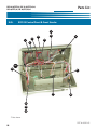
Overview
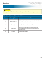
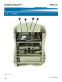
3-13. Filter Pan Assembly
1
3
2
3*
4
6
5
36
EOF-10-10/FFLT/24, EOF-10-10/FFLT/24/24
EOF-20/FFLT/24, EOF-20/FFLT/24/24
Overview
! WARNING
• Never remove the Filter Pan while it contains Liquid Shortening.
This could result in oil
spillage or possible burn injury. Please see Section 5-4. Removal of Liquid Shortening.
! CAUTION
• Always use Oven Mitts when using any of these parts. Parts will become very hot during
normal use.
3-13. Filter Pan Assembly
Item
Description
1
Hold Down Lever
(4 Levers)
Locks & tightly holds the hold-down frame, sealing the filter
paper against the pan bottom.
2
Hold Down Frame
Holds & seal the filter paper against the pan bottom.
3
Filter Paper
Optional Filter Media
3*
(SSFS)
Function
Filters finer particles of sediment from the cooking oil. The
system requires at least (1) piece of Filter Paper, (2) may be
used.
Renewable, Stainless Steel Filter Screen. Optional
alternative for Filter Paper. Can be cleaned and reused many
times.
Filter Pan Crumb Screen
Captures large crumbs & particles of sediment as oil is
drained into Filter Pan, providing an additional component of
the filtering process.
5
Filter Pan
Filters cooking oil after every (4) cook cycles. The Filter Pan
is easily removable for cleaning and filter paper changes. It
features casters for portability. A permanent perforated
screen is affixed to the pan bottom to support the filter paper
and aid in protecting the filter pump from unintended debris.
IT IS NOT A FILTER - FILTER PAPER MUST BE USED.
6
Filter Pan Quick-disconnect
4
Fitting for connection to the fryer’s oil filtration system.
Hose must be disconnected before removing the filter pan.
37
EOF-10-10/FFLT/24, EOF-10-10/FFLT/24/24,
EOF-20/FFLT/24, EOF-20/FFLT/24/24
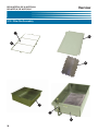
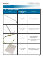
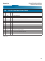
3-14.
Accessories (Included)
Part
38
Overview
Description/Part
Number
Function
Kettle Drain Brush
P/N: 71025
Used for cleaning the Fry Pot.
Drain Brush, Small
P/N: 73235
Used for cleaning the FFLT drain
Stir Paddle
P/N: 77775
Used for stirring Hot Oil and
Product being cooked.
Fry Vat Clean Brush
P/N: 71100
Used for cleaning Fry Pot and
Elements.
Crumb Shovel
P/N: 30059
Used for removing sediment from
the Filter Pan.
EOF-10-10/FFLT/24, EOF-10-10/FFLT/24/24
EOF-20/FFLT/24, EOF-20/FFLT/24/24
Overview
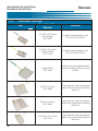
3-14.
Accessories (Included)
Part
Description/Part
Number
Function
L- Shaped Brush
P/N: 73233
Used for cleaning between
elements.
Vat Drain Clean Out
P/N: 36577
Used to clear excessive sediment
build up from the Vat Drain.
Wand Hose
P/N: 33667
FFLT Drain Screen
P/N: 70085
Used for removing liquid
shortening from unit.
Note: Not intended for washing
down the fry vat.
Used to allow excess oil to drain
from freshly cooked product.
39
EOF-10-10/FFLT/24, EOF-10-10/FFLT/24/24,
EOF-20/FFLT/24, EOF-20/FFLT/24/24
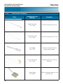
3-14.
Overview
Accessories (Included)
Part
Description/Part
Number
Function
(1) EOF-20 Fry Basket
(Blue Handle)
P/N: 70420
Used for cooking product in the
EOF-10-10 or the EOF-20.
(1) EOF-20 Fry Basket
(Yellow Handle)
P/N: 71109
Used for cooking product in the
EOF-10-10 or the EOF-20.
Scoop Basket
P/N: 70430
40
Used for removing cooked product
when batch cooking without using Fry
Baskets.
EOF-20 Fry Screen
P/N: 70083
Used to prevent excess breading or
product from contacting the Heating
Elements.
EOF-24 Fry Screen
P/N: 70084
Used to prevent excess breading or
product from contacting the Heating
Elements.
(2) EOF-10-10 Fry Screen
P/N: 71110
Used to prevent excess breading or
product from contacting the Heating
Elements.
EOF-10-10/FFLT/24, EOF-10-10/FFLT/24/24
EOF-20/FFLT/24, EOF-20/FFLT/24/24
Overview
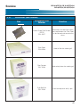
3-15.
Accessories (Not Included)
Part
Description/Part
Number
Function
Renewable, reusable filter media;
Stailess Steel Filter Screen
direct replacement for Filter Paper.
(SSFS)
Can be cleaned and reused many
P/N: 41017
times.
Filter Paper
P/N: 60328
Used to filter the cooking oil.
Filter Powder
P/N: 72004
Used to help clean the cooking oil.
Fryer Boil-Out
P/N: 72003
Used to help clean the fry pot.
41
EOF-10-10/FFLT/24, EOF-10-10/FFLT/24/24,
EOF-20/FFLT/24, EOF-20/FFLT/24/24
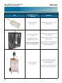
3-15.
Overview
Accessories (Not Included)
Part
Description/Part
Number
Function
EOF-24 Fry Basket
P/N: 70421
Sized for use in the 24” Vat to
cook product.
Fryer Tool Caddy/Splash
Guard
Left-Side: P/N 71523
Right-Side: P/N 71524
(Tools come standard with
Fryer or sold separately)
Giles Oil Caddy
P/N: 79187
Dual purpose Fryer attachment (no
tools required)
Store and organize Fryer Tools right
at the fryer.
Acts as Splash Guard to keep oil
splatter or splash off the floor or
adjacent equipment.
A portable oil disposal container
with a capacity of 80lbs of
liquid shortening.
Note: For use with filtered, warm
oil only. No crumbs or debris.
42
EOF-10-10/FFLT/24, EOF-10-10/FFLT/24/24
EOF-20/FFLT/24, EOF-20/FFLT/24/24
Unit Preparation
4. Unit Preparation
Giles Enterprises takes pride in the quality of its workmanship. Every effort has been made to ensure that
your unit is in good operating condition when received. Each unit must pass rigorous quality control testing
prior to shipment. To further ensure optimum operation, a brief operational check-out of your new fryer must
be conducted as described in this section.
! CAUTION
• Before attempting to operate the unit, refer to Section 3 to familiarize yourself with the various
control functions. Once you have read and fully understand Section 3, please follow the steps
below precisely in order to prevent equipment damage or malfunction.
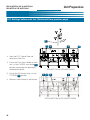
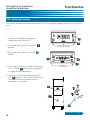
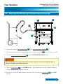
4-01. Settings before each test
Please ensure each unit’s control panel and valves are set to the following before proceeding to each test.
2
1
1. Power Switch is in the OFF 1 position.
EOF-20 or EOF-24
2. Heat Switch is in the OFF 2 position.
2
2
1
EOF-10-10
Continued next page
43
EOF-10-10/FFLT/24, EOF-10-10/FFLT/24/24
EOF-20/FFLT/24, EOF-20/FFLT/24/24
Unit Preparation
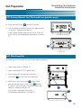
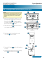
4-01. Settings before each test (Continued from previous page)
3
3
4
3
3
3. Open the FFLT Cabinet Door and
remove the Filter Pan.
4. Ensure the Drain Valve Handle on each
unit is in the CLOSED and Locked 3
position (tab pushed thru opening &
tucked behind panel).
5. Ensure the Oil Diverter Valve is in the
TO FRYER 4 position.
EOF-20/FFLT/24 or EOF-20/FFLT/24/24
3
3
4
3
6. Remove Crumb Screen(s) and Baskets.
EOF-10-10/FFLT/24 or EOF-10-10/FFLT/24/24
44
3
EOF-10-10/FFLT/24, EOF-10-10/FFLT/24/24
EOF-20/FFLT/24, EOF-20/FFLT/24/24
Unit Preparation
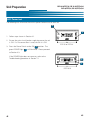
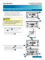
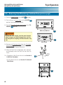
4-02. Power test
The following test will ensure the unit has power. Perform test on each unit.
2
1
1. Follow steps shown in Section 4-1.
2. Ensure the main circuit breaker supplying power the unit
is ON. If a Disconnect Box is used, ensure it is ON.
EOF-20 or EOF-24
3. Press the Power Switch to the ON 1 position. The
green POWER light 2 will illuminate. Please proceed
to Section 4-3.
If the POWER light does not come on, refer to the
Troubleshooting procedure in Section 7-1.
2
1
EOF-10-10
45
45
EOF-10-10/FFLT/24, EOF-10-10/FFLT/24/24
EOF-20/FFLT/24, EOF-20/FFLT/24/24
Unit Preparation
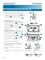
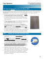
4-03. Heating Element test
The following test will ensure the Heating Element is being powered. Perform this test on each Fry Pot.
!
DANGER
•DO NOT touch the Heating Elements.
The Heating Elements are very hot and skin contact with the
Heating Elements may result in severe burns.
1
1. Follow steps shown in Section 4-1.
2. Ensure Power Switch is in the OFF position.
3. Liberally dampen a sponge with water and wipe down the
Heating Element 1 .
1
4. Press the Power Switch to the ON 2 position.
5. Wait until the Controller display 3 reads “HOLD.”
3
6.a.For the EOF-20 or EOF-24 only, press the Set Temp 4
button, the display should read 350. If not, set the temperature to 350, see Section 5-1.2. Programming the Cooking
Temperature.
6.b.For the EOF-10-10 only, press the left or right arrow 5
button to select the left or right cooking vat, then press the
Set Temp 6 button, the display should read 350. If not,
set the temperature to 350, see Section 5-1.2.
Programming the Cooking Temperature.
7.
7
4
2
9
8
7
3
EOF-20 or EOF-24
3
6
7
Press the Heat Switch to the HEAT 7 position. Leave in
the HEAT position NO MORE THAN 10 SECONDS.
Note: Should the Controller Scrolling Display 8 read
2
“Check Oil Level”, press the Power Switch 9 to the OFF
position and proceed to the next step.
9
8
5
8
EOF-10-10
Continued next page
46
EOF-10-10/FFLT/24, EOF-10-10/FFLT/24/24
EOF-20/FFLT/24, EOF-20/FFLT/24/24
Unit Preparation
4-03. Heating Element test (Continued from previous page)
8. Press the Heat Switch 10 to the OFF position
9. The wet element should dry quickly dry, approximately
15 seconds. Proceed to Section 4-4.
10
If the Heating Element does not dry within 15-30 seconds, refer to the Troubleshooting procedure in Section
7-1.
EOF-20 or EOF-24
10
10
EOF-10-10
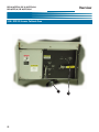
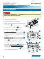
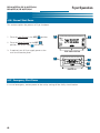
4-04. Filter Pump Test
The following test will ensure the Filter Pump is operating correctly.
1. Follow steps shown in Section 4-1.
2. Open Landing Table (FFLT) Cabinet Door.
3. Place the palm of your hand over the Quick
Disconnect 1 for the Filter Pan connection.
4. Briefly press the Pump Switch 2 to the PUMP
position and then return it to the OFF 3 position.
If suction is felt on the palm, the pump is operating
correctly. Proceed to Section 4.5.
If no suction is detected, refer to the
Troubleshooting procedure in Section 7-2.
1
2
3
47
EOF-10-10/FFLT/24, EOF-10-10/FFLT/24/24
EOF-20/FFLT/24, EOF-20/FFLT/24/24
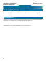
Unit Preparation
4-05. Perform Boil Out Procedure
Perform a Boil Out Procedure to remove any dirt, dust or debris that may have accumulated during shipping.
Follow Section 6-1 Boil Out Procedure. After performing the Boil Out Procedure proceed to Section 4-6.
4-06. Clean Filter Pan
Thoroughly clean the Filter Pan to remove any dirt, dust or debris that may have accumulated during shipping.
Follow Section 6-2 Cleaning the Filter Pan and replacing Filter Paper after Boil Out.
Fryer preparation is now complete; proceed to the Fryer Operation Section.
48
Fryer Operation
EOF-10-10/FFLT/24, EOF-10-10/FFLT/24/24
EOF-20/FFLT/24, EOF-20/FFLT/24/24
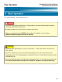
5. Fryer Operation
This section describes how to operate the unit.
!
DANGER
• Turn off the unit and turn off the fryer’s circuit breaker in the main circuit breaker box before
cleaning or performing maintenance.
• DO NOT hose down the unit’s interior or exterior with water.
• Failure to comply with these DANGER notices will result in death or serious injury,
equipment/property damage, and void the warranty.
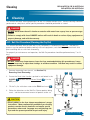
! CAUTION
• Ensure the unit is positioned in a secure, safe location ... casters with brakes must have the
brake applied.
• Consult an electrician to ensure all electrical specifications have been met and the unit is
properly grounded. The wiring diagrams provided with this unit should aid the electrician while
installing the fryer.
• Due to the high temperature of oil during cooking operations, it is extremely important that the
user exercise caution when working with or around this equipment to avoid personal injury.
49
EOF-10-10/FFLT/24, EOF-10-10/FFLT/24/24,
EOF-20/FFLT/24, EOF-20/FFLT/24/24
Fryer Operation
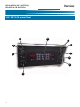
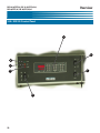
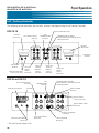
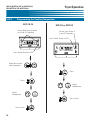
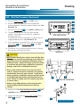
5-01. Cooking Controller
The following section describes the functions, features and programming of the Cooking Controller.
RESET ALARM BUTTON
EOF-10-10
DISPLAY
(LEFT VAT)
LEFT TIMER SELECT
BUTTON
SET
TEMPERATURE
BUTTON
TEMPERATURE & TIMER
ADJUSTMENT & ELEVATOR UP OR
DOWN BUTTONS
DISPLAY
(RIGHT VAT)
SCROLLING
DISPLAY
SCROLLING
DISPLAY
DISPLAY INDICATOR
LIGHTS (LEFT VAT)
LEFT VAT
TIMER
MENU
BUTTONS
LEFT VAT
TEMP &
BASKET
SELECT
BUTTON
RIGHT VAT
TEMP &
BASKET
SELECT
BUTTON
RIGHT VAT
TIMER
MENU
BUTTONS
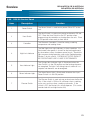
EOF-20 or EOF-24
LEFT TIMER SELECT
BUTTON
SCROLLING DISPLAY
SET
TEMPERATURE
BUTTON
TEMPERATURE & TIMER
ADJUSTMENT & ELEVATOR UP OR
DOWN BUTTONS
DISPLAY
RESET ALARM
BUTTON
RIGHT TIMER
SELECT BUTTON
RIGHT TIMER MENU
BUTTONS
RIGHT ELEVATOR
BUTTON*
DISPLAY INDICATOR
LIGHTS
* -Basket Elevator Option Only
50
LEFT TIMER MENU
BUTTONS
LEFT ELEVATOR
BUTTON*
EOF-10-10/FFLT/24, EOF-10-10/FFLT/24/24
EOF-20/FFLT/24, EOF-20/FFLT/24/24
Fryer Operation
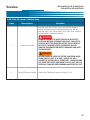
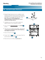
5-01.1.
Buttons and Functions
Used to set and display cooking temperature.
Used to increase or decrease cooking time and temperature.
Used to set and recall cooking times.
Used to silence alarm.
EOF-10-10: Used to select Left-Right Vat and Basket Elevator.
EOF-20 or EOF-24: Used to select Left or Right Basket Elevator. (Basket Elevator
Option Only)
Used to select the Left Basket Timer.
Used to select the Right Basket Timer.
Used to display cooking times and temperature.
Scrolls various status information.
51
EOF-10-10/FFLT/24, EOF-10-10/FFLT/24/24,
EOF-20/FFLT/24, EOF-20/FFLT/24/24
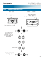
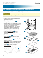
5-01.2.
Fryer Operation
Programming the Cooking Temperature
EOF-10-10
Ensure both Heat Switches
are in the OFF position
EOF-20 or EOF-24
Ensure Heat Switch is
in the OFF position
Press Power Switch to ON
Press Power Switch to ON
Select left or right
side to program
Press
Press
Adjust
temperature
Adjust
temperature
Press to set
Press to set
52
EOF-10-10/FFLT/24, EOF-10-10/FFLT/24/24
EOF-20/FFLT/24, EOF-20/FFLT/24/24
Fryer Operation
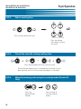
5-01.3.
Programming a Cooking Time
EOF-20 or EOF-24
EOF-10-10
Ensure Heat Switch is
in the OFF position
Ensure both Heat Switches
are in the OFF position
Press Power Switch to ON
Press Power Switch to ON
or
Press & hold both the
desired Basket Timer
Button (left or right) and
the desired Menu # Key
for 5 seconds
+
Adjust the time
Press the desired Basket
Timer Button again to
set
or
53
EOF-10-10/FFLT/24, EOF-10-10/FFLT/24/24,
EOF-20/FFLT/24, EOF-20/FFLT/24/24
5-01.4.
Fryer Operation
Start a cooking time
x2
or
Press the desired Basket Timer.
Press the desired
menu button twice to
start timer.
5-01.5.
Cancel the currently running cooking time
+
or
+
Press the desired Basket Timer twice to cancel.
(Basket Elevator Option Only) If cancelled after the Basket Lift has
been lowered, the Lift will raise when the program is cancelled.
5-01.6.
Manually lowering and raising the cooking basket (Basket Lift
Only)
Press the
desired Basket
Elevator.
54
Press to lower or
raise the cooking
basket.
EOF-10-10/FFLT/24, EOF-10-10/FFLT/24/24
EOF-20/FFLT/24, EOF-20/FFLT/24/24
Fryer Operation
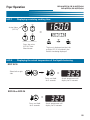
5-01.7.
Displaying remaining cooking time
Active Menu
(LED lit)
=
Press the active
(LED lit) Timer
Menu button
5-01.8.
The time is displayed and the Left
or Right LED is lit to identify the
Basket time being displayed.
Displaying the actual temperature of the liquid shortening
EOF-10-10
Select left or right
side
=
Press and Hold
for 5 seconds
Actual temperature will
display for 20 seconds
EOF-20 or EOF-24
=
Press and Hold
for 5 seconds
Actual temperature will
display for 20 seconds
55
EOF-10-10/FFLT/24, EOF-10-10/FFLT/24/24,
EOF-20/FFLT/24, EOF-20/FFLT/24/24
Fryer Operation
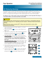
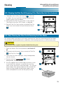
5-02. Cooking Procedure
This section describes the cooking process for the unit. This procedure applies to the EOF-20 and EOF-24
units.
1. Program the Controller to the desired
temperature, See Section 5-1.2.
2
1
2. Ensure the Power Switch is in the OFF 1
position.
EOF-20 or EOF-24
3. Ensure the Heat Switch is in the OFF 2
position.
2
2
1
4. Ensure the Drain Valve is pushed in and locked
in the CLOSED 3 position (tab thru opening
& tucked securely behind panel).
EOF-10-10
5. Fill the Fry Pot with liquid shortening to the
ADD 4 level only. The Fry Pot is filled only to
this level to allow for expansion of liquid
shortening as it is heated.
4
3
3
Continued next page
56
EOF-10-10/FFLT/24, EOF-10-10/FFLT/24/24
EOF-20/FFLT/24, EOF-20/FFLT/24/24
Fryer Operation
5-02. Cooking Procedure (Continued from previous page)
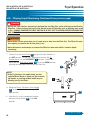
6. Press the Power Switch 5 to the ON
position. The Power Light 6 will turn on. If
the unit is equipped with the Basket Elevators
and you wish to activate the lifts, place the
Basket Elevator Switch 7 in the ON position.
6
10
11
8
9
NOTE:
• If an alarm sounds when Power Switch is
placed in the ON position and the Scrolling
Display reads “Drain Open - Close & Push
Reset”, follow step 4, above and then press
Alarm Reset on the Cooking Controller.
5
7
EOF-20 or EOF-24
10
10
11
9
11
9
8
8
6
7. Press the HEAT Switch 8 to the ON position. The
Heat Light 9 will illuminate, the display 10 will
5
7
EOF-10-10
read “HOLD” and the Scrolling Display 11 will
read “Oil Heating”. Oil will begin to heat to the
programmed setpoint temperature .
NOTE:
• On the first heating of the day, particularly if
the cool shortening is in a thickened state, it
is recommended that the vat be stirred
occasionally during heating to prevent false
Hi-Limit or Low Oil alarms.
Continued next page
57
EOF-10-10/FFLT/24, EOF-10-10/FFLT/24/24,
EOF-20/FFLT/24, EOF-20/FFLT/24/24
Fryer Operation
5-02. Cooking Procedure (Continued from previous page)
NOTE:
• The following step will help remove any cold
areas in the heated Liquid Shortening which
will allow the product to be cooked more
evenly.
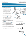
8. Once oil has reached the first preheat, an alarm
will sound and the Scroll Display will read “Stir
Oil and Push Reset” 11 . Using the supplied
Stir Paddle, thoroughly stir the Cooking Oil, then
press the Alarm Reset 12 button.
9. When the Heat Light 13 goes out the Oil has
reach setpoint temperature.
11
12
13
EOF-20 or EOF-24
12
13
13
11
11
EOF-10-10
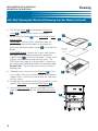
10. Check the oil level, it should now be at the
FULL Mark 14 . Add if needed.
14
16
17
11. Place the Fry Screen 15 into Fry Pot (handles to
the sides).
15
12. (Basket Elevator Option Only) Place the Cooking
Basket 16 onto the Basket Carrier 17 .
Continued next page
58
EOF-10-10/FFLT/24, EOF-10-10/FFLT/24/24
EOF-20/FFLT/24, EOF-20/FFLT/24/24
Fryer Operation
5-02. Cooking Procedure (Continued from previous page)
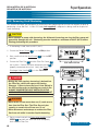
13. We recommend placing uncooked product into the
Cook Basket while in the up position, then
lowering the basket into the oil. However,
uncooked product may be placed into the Cooking
Basket after it has been lowered into the oil.
19
18
! CAUTION
•
EOF-20 or EOF-24
Use extreme caution when placing product into
the HOT shortening as severe burns are
possible should hands contact hot oil or in the
event of unexpected oil splash.
19
14. (Basket Elevator Option Only) Press the desired
Basket Lift Button 18 . Then press the Down
EOF-10-10
18
Arrow 19 . Cook Basket will lower.
(Basket Hanger Option Only) Place Baskets in Fry
Pot, resting on Fry Screen 20 .
20
21
15. Press desired Basket Timer 21 Button , then press
23
22
the desired Menu Time 22 Button two times. The
the time will start counting down and the Scrolling
Display will read “Cooking” 23 .
EOF-20 or EOF-24
21
23
23
EOF-10-10
22
Continued next page
59
EOF-10-10/FFLT/24, EOF-10-10/FFLT/24/24,
EOF-20/FFLT/24, EOF-20/FFLT/24/24
Fryer Operation
5-02. Cooking Procedure (Continued from previous page)
25
16. After 60% of the cooking time has elapsed from the
selected cooking time, a Stir Cycle alarm will sound and
the Scrolling Display will read “Stir Product” 24 . Using
the Stir Paddle 25 and wearing oven mitts, stir the
product and then press the Alarm Reset Button 26 .
17. With Basket Elevators: At the end of the
programmed cooking time, an alarm will sound and
the Display will read “DONE” 27 . The Scrolling
Display will read “Left Timer” or “Right Timer” 24 .
The Cook Basket 28 will automatically be raised
27
26
24
from the oil. Press Alarm Reset Button 26 to
silence the alarm.
With Manual Baskets: At the end of the
programmed cooking time, an alarm will sound and
the Display will read “DONE” 27 . The Scrolling
Display will read “Left Timer” or “Right Timer” 24 .
Using Oven Mitts lift the Basket 28 from the oil and
27
EOF-20 or EOF-24
26
24
hang it on the top bar of the Basket Hanger 29 .
27
Press the Alarm Reset Button 26 to silence the
alarm.
24
18. Allow cooked product to adequately drain.
19. Using Oven Mitts remove the Basket and dump
cooked product onto the FFLT landing table or into
an appropriate container.
EOF-10-10
28
28
29
20. • To continue cooking return to step 6 of this
procedure.
• To shut-down the unit, see Section 5-5 Normal
Shut-Down.
Basket Elevator
60
Basket Hanger
Fryer Operation
EOF-10-10/FFLT/24, EOF-10-10/FFLT/24/24
EOF-20/FFLT/24, EOF-20/FFLT/24/24
5-03. Filtering Fryer Shortening
This section describes the procedure for filtering the fryer shortening through the built-in filtration system.
The filtration system circulates used cooking oil through filter media in the Filter Pan and back to the
Cooking Vat. Adhering to this process can increase shortening life up to 50%. Cooking Controllers on
each fry vat are preset to alert the operator to filter shortening after every fourth (4th) load cooked.
Two different types of filter media can be used with the EOF Fryer, either disposable Filter Paper or
a renewable stainless steel mirco-mesh filter screen (SSFS)
! CAUTION
• Never attempt to filter cold shortening; the thickened shortening can clog the filter pump and
potentially damage the unit. Shortening must be heated to a minimum of 200°F (93°C) before
filtering.
• Parts of the Fryer may be extremely HOT! Always wear thermal mitts or gloves when
performing this procedure.
1
1. After the fourth (4th) load has been cooked in a vat, the oil
needs to be filtered.
2. Place the Heat Switch 1 for the unit to be filtered in the
OFF position .
3. Open the FFLT Cabinet Door. While wearing hand protection,
disconnect the Filter Pan quick-disconnect hose 2 and
remove the empty Filter Pan 3 from under the unit.
EOF-20 or EOF-24
4. Using Filter Paper: Ensure that (1) sheet of Filter Paper is
installed correctly in Filter Pan and that the Hold-down Frame
is securely locked in place. Two (2) pieces of paper are
required for older models without the permanent Filter
Pan screen.
Using Renewable Mesh Screen: Ensure the Screen is free
of residue and properly seated in the Filter Pan bottom. Be
certain that no debris is trapped underneath the gasket and
that the Hold-down Frame is securely locked in place.
5. Evenly distribute approximately 4-3/4 oz. of an appropriate
Filter Powder evenly over the filter media surface ... Giles
#72004 is recommended.
6. Ensure the Filter Pan Cover 4 is in place, then reposition
Filter Pan under the unit. Reconnect the Filter Pan quickdisconnect hose 2 to the proper fitting on the Fryer.
EOF-10-10
5
2
4
3
Continued next page
61
EOF-10-10/FFLT/24, EOF-10-10/FFLT/24/24,
EOF-20/FFLT/24, EOF-20/FFLT/24/24
Fryer Operation
5-03. Filtering Liquid Shortening (Continued from previous page)
!
DANGER
• During the next step hot shortening is drained into the Filter Pan, which will expose the Heating
Elements. Failure to have the fryer’s Heat Switch in the OFF position prior to draining may result
in fire. ALWAYS CONFIRM THE HEAT SWITCH IS IN THE “OFF” POSITION BEFORE DRAINING THE
THE COOK VAT.
! WARNING
• Never drain oil from more than one (1) cook vat at a time into the Filter Pan!
The Filter Pan only
has capacity to contain the oil from one (1) vat.
• Never disconnect and attempt to remove the Filter Pan from unit while it contains liquid
shortening.
7.
Confirm that the Heat Switch 1 for the unit to be filtered is in
the OFF position. On the FFLT lower panel, ensure the Oil
Diverter Valve is in the TO FRYPOT 5 position. Unlock and
slowly pull the Drain Valve Handle 6 out to the OPEN position,
allowing the cooking oil to drain into the Filter Pan.
6
NOTE:
• If the Fry Vat does not readily drain, use the
supplied Drain Brush or Clean-out Tool to break
up crumbs or cooking residue which may be
blocking the Fry Vat Drain.
8. Move the Pump - Oil Return Valve Handle
7 for the unit to be filtered to the VAT
FILL position.
7
8
9. After the Fry Vat has completely drained,
place the Pump Switch 8 in the ON
position.
Continued next page
62
EOF-10-10/FFLT/24, EOF-10-10/FFLT/24/24
EOF-20/FFLT/24, EOF-20/FFLT/24/24
Fryer Operation
5-03. Filtering Liquid Shortening (Continued from previous page)
10. The used oil will be pumped from the
Filter Pan, through the filter media and
recirculated back to the Fry Vat 9 .
Leave the Drain Valve open and allow
the oil to continually circulate through
the system for at least 5 minutes.
During this time it is advisable to
remove the Crumb Screen and use the
Pot Brush and Element Brush to scrub
the vat walls and elements, allowing
residue to be flushed into the Filter Pan.
OR
9
9
7
7
11. After 5 minutes, replaced the Crumb
Screen if removed, push in and lock the
Drain Valve Handle 10 in the CLOSED
position and allow the Fry Vat to refill.
When all oil has been pumped back to
the vat, air bubbles will appear at the
pump discharge inside the vat.
10
12. After the Fry Vat has refilled, place the Pump
Switch 11 in the OFF position.
13. Position the Pump Oil Return Lever 12 on the
unit being filtered to the CLOSE position.
11
14. Ensure the Fry Pot contains the proper level of
liquid shortening ... add if needed.
15. • To continue cooking, See Section 5-2, Cooking
Procedure.
• To discontinue cooking, See Section 5-5,
Normal Shut-Down.
12
63
EOF-10-10/FFLT/24, EOF-10-10/FFLT/24/24,
EOF-20/FFLT/24, EOF-20/FFLT/24/24
Fryer Operation
5-04. Removing Used Shortening
This section describes the procedure for removing used shortening from the unit for disposal or prior to
performing a fryer Boil Out. A Giles Oil Caddy (not supplied) is depicted as being used for disposal of
used shortening.
! CAUTION
• Never attempt to pump cold shortening; the thickened shortening can clog the filter pump and
potentially damage the unit. Shortening must be heated to a minimum of 200°F (93°C) before
filtering performing this procedure.
1. If shortening is cold, heat to 200°F (93°C).
2
2. Ensure the Power Switch 1 is in the ON position.
3. Next, confirm that the Heat Switch 2 is in the OFF
position.
1
4. Ensure the Filter Pan 3 and the Filter Pan Cover 4
are in place. Confirm the quick disconnect hose 5 is
properly connected the to unit. Verify the Pump
Discharge Valve Handle 6 is in the TO FRYER
position.
!
EOF-20 or EOF-24
2
2
DANGER
1
EOF-10-10
• During the next step hot shortening is drained into
the Filter Pan, which will expose the Heating
Elements. Failure to have the fryer’s Heat Switch in
the OFF position prior to draining may result in fire.
ALWAYS CONFIRM THE HEAT SWITCH IS IN THE
“OFF” POSITION BEFORE DRAINING THE COOK VAT.
6
5
4
! WARNING
• Never drain oil from more than one (1) cook vat at a
3
time into the Filter Pan! The Filter Pan only has
capacity to contain the oil from one (1) vat.
• Never disconnect and attempt to remove the Filter
Pan from unit while it contains liquid shortening.
5. Slowly unlock and pull the Drain Valve Handle to the
OPEN 7 position and allow the oil to completely
drain into the Filter Pan.
64
7
Continued next page
EOF-10-10/FFLT/24, EOF-10-10/FFLT/24/24
EOF-20/FFLT/24, EOF-20/FFLT/24/24
Fryer Operation
5-04. Removing Used Shortening (Continued from previous page)
12
11
8
13
9
10
6. Connect the supplied Oil Discharge Hose 8 to the Discharge Hose Coupling 9 .
7.
Place the discharge end into an appropriate Hot Oil Disposal Container 10 (Giles Oil Caddy is shown)
8. Turn the Pump Discharge Valve Handle 11 to the TO DISCHARGE HOSE position.
! WARNING
• When handling the Discharge Hose during the next step, be sure the wear thermal mitts or
gloves, as the hose can become very hot.
9. Place the Pump Switch 12 in the PUMP position. Allow the pump to run until all liquid shortening
has been pump into the Disposal Container.
10. After all the used oil has been removed from the Filter Pan, place the Pump Switch 13 to the OFF
position.
Continued next page
65
EOF-10-10/FFLT/24, EOF-10-10/FFLT/24/24,
EOF-20/FFLT/24, EOF-20/FFLT/24/24
Fryer Operation
5-04. Removing Used Shortening (Continued from previous page)
11. Place the Power Switch in the OFF 14 position.
12. Push and lock the Drain Valve to the CLOSED 15
position (tab tucked behind panel).
13. Turn the Pump Discharge Valve Handle to the TO
FRYPOT 16 position.
EOF-20 or EOF-24
14
! WARNING
• During the next step be sure the wear thermal
mitts or gloves as the Discharge Hose and the
Discharge Hose Coupling will have become very
hot.
14
EOF-10-10
14. Remove the Discharge Hose from the Discharge
Hose Coupling and drain any oil remaining in the
hose into the Oil Disposal Container.
15. Allow the Filter Pan to thoroughly cool. Remove
and thoroughly clean the Filter Pan and Filter Pan
Cover.
16. • To perform a Boil Out on the unit see Section 61, Boil Out Procedure.
15
• To shut down the unit see Section 5-5, Normal
Shut-Down.
16
66
Fryer Operation
EOF-10-10/FFLT/24, EOF-10-10/FFLT/24/24
EOF-20/FFLT/24, EOF-20/FFLT/24/24
5-05. Using the Optional Renewable Filter Media (SSFS)
This section describes use and care of the renewable, stainless steel, Filter Screen (SSFS). The SSFS is a
direct replacement for paper filter media that can cleaned and reused many times. It is an optional item
(Giles #41017) that can be ordered with new units or purchased later as a filter paper alternative.
1. Place the SSFS into the Filter Pan same as filter paper. DO NOT
use filter paper and the Screen at the same time.
2. Ensure that the edge gasket is flat against Pan bottom. Position
the Hold-down Frame and lock into place with the locking levers.
Levers may not fully close when using the Screen ... this will not
affect performance.
3. For best filtering results, always use an appropriate filter aid, such
as Giles #72004 Filter Powder. Distribute the prescribed amount
evenly over the surface, same as with filter paper.
4. After performing a regular filtering cycle, see Section 5-03,
Filtering Shortening, clean accumulated filter sediment from the
SSFS surface with the supplied Crumb Shovel, or other suitable
utensil, and discard. It might be necessary to remove the SSFS to
brush remaining residue from its surface.
5. If Screen is removed, do not allow filter residue to fall into the Filter
Pan bottom and be certain to reinstall the screen with the soiled
side up; wipe any residue from the edge gasket before installing.
5-05.1.
Washing the Renewable Filter Media (SSFS)
1. It is not necessary to wash the SSFS Filter Screen after every
filtering cycle.
2. On a weekly basis, remove the SSFS Screen and clean it in a sink,
using ONLY hot water and a soft bristle brush. DO NOT USE
SOAP or OTHER CLEANERS when washing the Screen. Doing so
may affect oil life and quality. It is highly unlikely that soap residue
can be completely rinsed from the screen and it will eventually be
transferred to the cooking oil during subsequent filter cycles.
4. DO NOT USE OVEN CLEANERS or CAUSTIC PRODUCTS to
clean the Screen. These chemicals will damage the silicone edge
gasket and residue can be transferred to the cooking oil.
5. Before reinstalling the clean SSFS in the Filter Pan, shake off
excess water and dry with a clean towel. Be certain screen is dry
before using. If possible, it is best to allow screen to dry overnight.
6. Take care not to cut or tear the silicone edge gasket. Inspect the
Screen weekly for damage, such as fraying, holes, damaged
gasket, etc. A damaged screen should be removed from service
and replaced immediately.
67
EOF-10-10/FFLT/24, EOF-10-10/FFLT/24/24,
EOF-20/FFLT/24, EOF-20/FFLT/24/24
Fryer Operation
5-06. Normal Shut-Down
This section explains the process of Fryer shutdown.
1. Place the Heat Switch in the OFF 1 position.
3
1
2. Place the Power Switch to the OFF 2
position, the Power Light 3 will turn off.
2
3. If required, turn off fryer supply power at the
main circuit breaker panel.
EOF-20 or EOF-24
1
1
3
2
EOF-10-10
5-07. Emergency Shut-Down
In case of emergency, remove power to the unit by turning off the facility circuit breaker.
68
Cleaning
EOF-10-10/FFLT/24, EOF-10-10/FFLT/24/24
EOF-20/FFLT/24, EOF-20/FFLT/24/24
6. Cleaning
This section describes cleaning operations for the EOF Model Banked Fryers. General cleaning should be
performed on a daily basis, other specific procedures should be performed as stated.
!
DANGER
• DO NOT wash down the unit’s interior or exterior with water from a spray hose or pressure-type
•
washer.
Failure to comply with these DANGER notices will result in death or serious injury, equipment or
property damage, and void the warranty.
6-01. Boil-Out Procedure (Cleaning the Fry Pot)
This section describes how to clean the Fry Vat; the process is referred to as Boil-Out. The Boil-Out
process must be performed before cooking with new equipment, and should be performed each time
prior to refilling the vat with fresh shortening.
For proper fryer maintenance and operation, the Boil-Out procedure should be performed every 7 to 14
days.
!
DANGER
• DO NOT, under any circumstances, leave the fryer unattended during this procedure as it may
become necessary to adjust heat settings to avoid vat overflow. Overflow may result in serious
equipment damage.
1. Remove shortening from the unit, see Section 5-4,
Removing Used Shortening.
2
2
2. Ensure the Drain Valve Handle is pushed in and locked in the
CLOSED 1 position and the Power Switch 6 is in the
OFF position.
OR
3. Fill the Fry Vat with clean water to the FULL level mark 2 .
4. Follow the directions on the Boil-Out Cleaner product being
used ... add the recommend amount of product to the vat.
1
1
! CAUTION
• Closely adhere to the fryer cleaner manufacturer’s usage
instructions. Many commercially available fryer cleaning
products contain caustic chemicals and require special
precautions when used. Improper use, may damage the
fryer and also present potential for personal injury.
1
Continued next page
69
EOF-10-10/FFLT/24, EOF-10-10/FFLT/24/24
EOF-20/FFLT/24, EOF-20/FFLT/24/24
Cleaning
6-01. Boil Out Procedure (Continued)
5. Place the Power Switch 3 in the ON position.
4
6. Set the Cooking Temperature to the temperature
recommended for the boil-out product being used. See
Section 5-1.2.
5
3
Place the Heat Switch 4 in the HEAT or ON position.
7.
6
8. The boil-out solution will heat to recommended
setpoint. See product instructions for suggested
cleaning cycle time.
If desired, one of the Timer buttons can be set for the
suggested boil-out time. See Section 5-1.3.
9. At the completion of the Boil-Out cycle time, place the
Heat Switch 5 and Power Switch 6 in the OFF
position.
EOF-20 or EOF-24
4
4
5
3
5
6
10. Disconnect Filter Pan quick-disconnect hose. Remove
the Filter Pan and Filter Pan Cover.
EOF-10-10
! CAUTION
• NEVER drain the Boil-Out solution into the Filter Pan!
It is corrosive and will cause damage to the Filter Pan,
Mesh Filter Screen (if equipped), Hold-Down Frame
and Filter Pump. Failure to comply could cause minor
to moderate personal injury, equipment or property
damage, and result in voiding the warranty.
OR
• Use a catch container that is heat rated for 300°F
(148°C). General-use plastic containers are typically
not desirable; they may melt or break. A leak-proof
metal container is preferable, but any container made
of suitable high-temperature rated material may be
used. Failure to comply with this caution may result
in serious injury.
8
8
7 NOT THE FILTER PAN
• Always wear rubber gloves and use thermal mitts
when handling and discarding the hot boil-out
solution.
11. Position a suitable Heat Resistant Container 7 (not
supplied) beneath the Fryer Drain.
12. Unlock and slowly pull the Drain Valve Handle to the
OPEN 8 position.
8
Continued next page
70
EOF-10-10/FFLT/24, EOF-10-10/FFLT/24/24
EOF-20/FFLT/24, EOF-20/FFLT/24/24
Cleaning
6-01. Boil Out Procedure (Continued)
13. Remove Screen from the vat and, as needed, use the
Pot Brush & Element Brush to scrub vat sides, bottom,
heating elements, etc. to remove oil residue. Rinse and
flush the Fry Vat thoroughly with clean warm water.
Note: Take care to avoid damaging the
temperature probes located inside the vat and
attached to heating elements.
9
14. Completely dry the vat with a clean dry towel and
properly dispose of the used boil-out solution.
12
15. Push in and lock Drain Valve Handle in the CLOSE 9
position.
16. Clean Filter Pan and replace Filter Media. See directions
in Section 6-02, Cleaning the Filter Pan & Replacing
Filter Media After Boil Out.
10
17. Re-install Filter Pan Cover 10 .
18. Position Filter Pan 11 under unit and connect Filter Pan
quick-disconnect hose to unit 12 .
11
19. Restart the fryer for cooking. See Section 5-2.
71
EOF-10-10/FFLT/24, EOF-10-10/FFLT/24/24
EOF-20/FFLT/24, EOF-20/FFLT/24/24
Cleaning
6-02. Cleaning the Filter Pan & Renewing Filter Media After Boil Out
This section explains the procedure for cleaning the Filter Pan and renewing the Filter Media. This should
be done each time the Boil-Out procedure (Section 6-01) is performed.
! CAUTION
• Use thermal mitts or gloves to protect hands from hot parts.
1. Filter Pan should have been removed prior to
draining boil-out solution.
2. Remove & clean Crumb Screen 1 , using a
biodegradable, non-toxic cleaner.
2
3. Use the supplied metal Crumb Scoop to remove
as much of the accumulated filter sediment as
possible from the filter media surface,
particularly around the edges. This will help
prevent debris from getting underneath the
renewed filter media or falling through the
perforated support screen and potentially
causing the filter pump to clog.
4. Clean the Filter Pan Cover 2 , using a
biodegradable, non-toxic cleaner. Dry it
thoroughly.
9
1
5. Turn the four Levers 4 to disengage the Holddown Frame 5 . Remove, clean and dry
Frame thoroughly.
4
5
6. Remove the Filter Media 6 , either Filter Paper
or Mesh Screen (SSFS).
6
Using Paper: Carefully roll up soiled filter sheet
and discard; avoid allowing filter debris to fall
through the permanent, perforated support
screen 7 in the Filter Pan bottom.
Using SSFS Screen: Remove the screen; avoid
allowing filter debris to fall through the
permanent, perforated support screen 7 in the
Filter Pan bottom. Using only hot water and a
soft bristle brush, clean screen in sink. Shake
out water and dry with clean dry towel. DO
NOT use soaps or cleaners of any kind when
washing the SSFS Screen!
72
7
8
EOF-10-10/FFLT/24, EOF-10-10/FFLT/24/24
EOF-20/FFLT/24, EOF-20/FFLT/24/24
Cleaning
6-02. Cleaning the Filter Pan & Renewing Filter Media After Boil Out (Continued)
7.
Thoroughly clean and dry the Filter Pan 8 . Flush out
any debris that may have fallen through the perforated
support screen in the Pan bottom.
8. Reassemble the Filter Pan with either (1) new sheet of
Filter Paper or the clean SSFS Screen, as applicable.
9. Reinstall Filter Pan Cover, position assembled Filter Pan
under Fryer and re-connect the quick-disconnect hose
9 .
9
8
6-03. Daily Cleaning the Filter Pan & Renewing the Filter Media
This section explains the process for the daily cleaning of the Filter Pan and renewing the Filter Media.
This procedure should be performed as required by actual cooking load, but at a minimum once daily.
! CAUTION
• Use thermal mitts or gloves to protect hands from hot parts.
1. Follow the Normal Shut-Down procedure, see Section 505.
2. Disconnect quick-disconnect hose; remove the Filter Pan
1 and Filter Pan Cover 2 .
2
3. Clean Filter Pan Cover thoroughly, using a biodegradable,
non-toxic cleaner.
10
4. Remove and clean Crumb Screen 3 , using a
biodegradable, non-toxic cleaner.
5. Use the supplied metal Crumb Scoop to remove as much
accumulated filter sediment as possible from the filter
media surface, particularly around the edges. This will help
prevent debris from getting underneath the renewed filter
media or falling through the perforated support screen,
which could potentially cause the filter pump to clog.
1
3
73
EOF-10-10/FFLT/24, EOF-10-10/FFLT/24/24
EOF-20/FFLT/24, EOF-20/FFLT/24/24
Cleaning
6-03. Daily Cleaning the Filter Pan & Renewing the Filter Media (Continued)
6. Turn the four Levers 4 to disengage the Hold-down
Frame 5 ... remove, clean and dry it thoroughly.
7.
Remove the Filter Media 6 , either Filter Paper or Mesh
Screen (SSFS).
4
5
Using Paper: Carefully roll up soiled filter sheet and
discard; avoid allowing filter debris to fall through the
permanent, perforated support screen 7 in the Filter Pan
bottom.
6
Filter Paper
or SSFS
Screen
Using SSFS Screen: Remove the screen; avoid allowing
filter debris to fall through the permanent, perforated
support screen 7 in the Filter Pan bottom. Simply shake
or brush remaining filter residue from the screen. The
SSFS Screen only requires washing weekly (it should also
be washed when performing the Boil-Out procedure), see
Section 5-06.1. Take care not to cut or tear the silicone
border gasket.
7
8
8. Thoroughly clean, rinse and dry the Filter Pan 8 . Flush
out any debris that may have fallen through the perforated
support screen. Stand Pan on end to drain any water from
the Pan’s tubing.
10. As applicable, reassemble the Filter Pan with either (1) new
sheet of Filter Paper or the cleaned SSFS Screen 6 .
11. Reinstall Filter Pan Cover, position assembled Filter Pan
under the unit and re-connect the Quick-disconnect Hose
9 .
9
74
EOF-10-10/FFLT/24, EOF-10-10/FFLT/24/24
EOF-20/FFLT/24, EOF-20/FFLT/24/24
Troubleshooting
7.
Troubleshooting
This section describes troubleshooting procedures. Refer to the wiring diagrams in Section 9 as an aid to
more detailed analysis, if needed.
7-01.
Temperature Control System
Problem
FRYER WILL NOT TURN ON:
No power light
Probable Cause
Repair Procedure
A. Not connected to power
source
A. Connect to power source
B. Faulty fuse or circuit breaker
B. Check fuse or breaker
C. Fuse holder cracked
C. Replace fuse holder
D. Faulty Power Switch
D. Replace Power Switch
E. Improper supply voltage
E. Connect to proper voltage
source
FRYER WILL NOT HEAT:
Power light ON. Heat light OFF.
A. Heat Switch not in “Heat (On)” A. Place Heat Switch in “Heat”
position.
position.
FRYER WILL NOT HEAT:
Power light ON.
Heat Switch in “Heat” position.
Heat light OFF.
A. Controller programmed below A. Set temperature controller to
actual oil temperature.
desired temperature.
B. Drain Valve open.
B. Close Drain Valve. Press Alarm
Reset Button on Controller.
C. Faulty cooking Controller.
C. Replace cooking Controller.
D. Variable probe shorted or
open.
D. Replace probe
E. Loose wire.
E. Repair loose wire.
F.
F. Replace faulty contactor.
Contactor failure.
G. Element bad.
G. Replace element.
H. Heat Switch bad.
H. Replace Heat Switch.
I.
I. Turn Power Switch Off and Add
Oil.
Low Oil Level
75
EOF-10-10/FFLT/24, EOF-10-10/FFLT/24/24,
EOF-20/FFLT/24, EOF-20/FFLT/24/24
Troubleshooting
7-01. Temperature Control System (Continued)
Problem
FRYER HEATING SLOW: (slow
recovery) Heat light stays ON.
FRYER HEATS SLOW: (short
cycling) Heat light OFF and ON
CONTINUOUSLY.
OIL TEMPERATURE ERRATIC:
OIL SMOKING:
76
Probable Cause
Repair Procedure
A. Incorrect Cooking procedures.
A. Consult Operations Manual for
proper Cooking procedure.
B. Element failing.
B. Replace bad Element.
C. Contactor failing.
C. Replace Contactor.
D. Loose Wire.
D. Repair Loose Wire.
E. Low Supply Voltage.
E. Supply proper Voltage.
A. Low supply Voltage.
A. Supply proper Voltage.
B. Variable probe touching element.
B. Reposition variable probe.
C. Faulty cooking Controller.
C. Replace cooking Controller.
A. Probe bad.
A. Replace Probe.
B. Contactor failing.
B. Replace Contactor.
C. Faulty cooking Controller.
C. Replace cooking Controller.
D. Loose Wire.
D. Repair loose Wire.
A. Oil being used too long.
A. Change oil.
B. Over temperature.
B. Check temperature setting.
C. Dirty element.
C. Clean elements, using Fry Vat
cleaning brush.
D. Faulty element.
D. Replace element.
E. Improper element voltage.
E. Supply proper Voltage.
F. Low Oil level.
F. Keep Oil at FULL Level.
EOF-10-10/FFLT/24, EOF-10-10/FFLT/24/24
EOF-20/FFLT/24, EOF-20/FFLT/24/24
Troubleshooting
7-01. Temperature Control System (Continued)
Problem
FRYER WILL NOT HEAT:
Power light ON. Heat Switch
in Heat position. High Limit light
ON.
Probable Cause
Repair Procedure
A. Power surge.
A. Turn Power Switch OFF for 5
seconds.
B. Sticking Contactor.
B. Replace Contactor.
C. Bad High Limit Board.
C. Replace High Limit Board.
D. High Limit Probe short or open. D. Replace High Limit Probe.
E. Line spikes or noise.
7-02.
E. Filter Line or remove noise
source.
Oil Filtration System
Problem
OIL NOT RETURNING TO FRY
POT:
Probable Cause
Repair Procedure
A. Pump Switch not in “Pump”
position.
A. Place Selector Switch in
“Filter/Pump” position.
B. Air Leak (hose, fittings, filter
paper).
B. Repair Air Leak.
C. Pump Motor Bad.
C. Replace Pump Motor.
D. Oil Pump Sticking.
D. Free Stuck Pump.
E. Diverter Valve not in “TO
FRYER” position.
E. Place Diverter Valve in “TO
FRYER” position.
F. Using pump to handle used
boil-out.
F. Disassemble and re-oil pump.
G. Old oil allowed to sit in pump.
G. Run clean oil through pump.
H. Oil cold or below 200°F (93°C)
in Filter Pan.
H. Remove Filter Pan and remove
cold oil from Filter Pan.
I. Filter Pan incorrectly assembled.
I. Assembly Filter Pan correctly.
J. Dirty Filter Pan.
J. Clean Filter Pan.
77
EOF-10-10/FFLT/24, EOF-10-10/FFLT/24/24,
EOF-20/FFLT/24, EOF-20/FFLT/24/24
7-03.
Troubleshooting
Basket Elevator System (Basket Elevator Option Only)
Problem
BASKET WILL NOT GO UP OR
DOWN
Probable Cause
Repair Procedure
A. Power not ON.
A. Press Power Switch to ON
position.
B. Faulty cooking Controller.
B. Replace cooking Controller.
C. Elevator micro-switch out of
adjustment.
C. Adjust Elevator micro-switch.
D. Faulty elevator micro-switch.
D. Replace elevator micro-switch.
E. Elevator switch not in ON posi- E. Press elevator switch to ON
tion.
position.
F. Faulty elevator motor.
78
F. Replace motor.
Parts List
EOF-10-10/FFLT/24, EOF-10-10/FFLT/24/24
EOF-20/FFLT/24, EOF-20/FFLT/24/24
8. Parts List
This section lists various parts that are available for replacement on the unit.
8–01. Parts Ordering and Service Information
If you require assistance or need repairs, please contact your Giles Representative to locate a service
agency in your area. For further assistance, please contact Giles Enterprises, Inc. at one of the following
phone numbers:
IN THE UNITED STATES, CANADA or MEXICO
Call 800.554.4537 during normal business hours, 8:00AM to 5:00PM Central Time. For emergency
equipment repair service after normal business hours, call 800.554.4537 and follow the recorded
prompts to obtain after-hours support..
IN ALL OTHER COUNTRIES
Call 334.272.1457 during normal business hours, 8:00AM to 5:00PM Central Time Zone and follow the
recorded prompts. For emergency equipment repair service after normal business hours call, 334-2721457 and follow the recorded prompts to obtain after-hours support..
WEBSITE:
Please visit our website: www.gfse.com. E-mail: [email protected]
The goal of the Giles team is to provide you with the best possible service and assistance. You can help
us accomplish this by obtaining the following information and having it readily available when calling. The
information is recorded on the Data/Serial Label attached to the Back Panel of each Fryer unit.
The area below may be helpful in recording information for use as a quick reference.
Model Number: ______________________________________
Serial Number: ______________________________________
Phase:
_______
Voltage: _______
Be ready prepared to describe the nature of the problem.
79
EOF-10-10/FFLT/24, EOF-10-10/FFLT/24/24,
EOF-20/FFLT/24, EOF-20/FFLT/24/24
8-02.
Parts List
EOF-10-10 Control Panel & Front Header
2
3
2
1
4
3
1
5
6
7
8
9
10
5
8
11
12
6
13
7
11
11
15
12
14*
13
* Not shown
REF #: 60221-10
80
EOF-10-10/FFLT/24, EOF-10-10/FFLT/24/24
EOF-20/FFLT/24, EOF-20/FFLT/24/24
Parts List
8-02.
Item
01
02
03
04
05
06
07
08
09
10
11
12
13
14*
15
EOF-10-10 Control Panel & Front Header
Part No.
21101
21102
23751
20366
23755
20315
20362
20365
21190
38215
21052
38213
38214
63778
20364
Qty.
2
2
2
1
2
2
2
2
1
1
3
2
2
1
1
Description
SOCKET, RELAY, 8 PIN, 300V, 10A, CR-5
RELAY, 8 PIN, 240V COIL, 10A
TERMINAL BLOCK, MA106,6 POLE
TRANSFORMER,18VA,CL2,115/230V,60HZ
THERMOSTAT, SAFETY, WATLOW, 450DEG
THERMOCOUPLE,13.5",STRAIGHT,J TYPE (REQUIRES P/N 45111 FERRULE)
THERMOCOUPLE,7.5 X 0.188,J-TYPE,STRAIGHT (REQUIRES P/N 45111 FERRULE)
THERMOCOUPLE, 12 INCH , J-TYPE, EOF-10 (REQUIRES P/N 45111 FERRULE)
SWITCH, ROCKER, ON-OFF, 250V, 20A, DPST
LIGHT, INDICATOR, GREEN,250VAC
SWITCH,ROCKER,ON-NONE-ON,250V,20A,DPDT
LIGHT, INDICATOR, ORANGE,250V
LIGHT, INDICATOR, RED,250VAC
LABEL, CONTROL PANEL, EOF-10-10
CONTROLLER, N7, DUAL DISPLAY, WATLOW
* Not shown
81
EOF-10-10/FFLT/24, EOF-10-10/FFLT/24/24,
EOF-20/FFLT/24, EOF-20/FFLT/24/24
8-03.
Parts List
EOF-10-10 Front Lower Cabinet
3
3
1
1
2
2
4*
5
5
6
7
8
9*
* Not shown
REF #: 60221-11
82
EOF-10-10/FFLT/24, EOF-10-10/FFLT/24/24
EOF-20/FFLT/24, EOF-20/FFLT/24/24
Parts List
8-03.
Item
01
02
03
04*
05
06
07
08
09*
EOF-10-10 Front Lower Cabinet
Part No.
40784
39258
40818
35151
21157
63986
21051
21164
39978
Qty.
2
2
2
1
2
1
1
1
1
Description
VALVE,BALL,1/2",S/S w/NON-STICK SEALS
HANDLE, DRAIN PULL
VALVE,BALL,1-1/4",DRAIN,SINGLE THREAD END
DOOR ASSEMBLY
SWITCH, LIMIT, 15A, 250V DRAIN SWITCH
LABEL, FRONT BRACE, EOF-10-10
LUG, 1/0-2/0 COPPER TERMINAL 125A 1/4" BOLT HOLE
POWER DIST,TERMINAL BLOCK
COVER, SERVICE CONNECTION, EOF-10-10
* Not shown
83
EOF-10-10/FFLT/24, EOF-10-10/FFLT/24/24,
EOF-20/FFLT/24, EOF-20/FFLT/24/24
8-04.
Parts List
EOF-10-10 Rear Upper & Lower Cabinet
3
2
4
1
6
13*
5
12
11
10
7
9
8
8
8
8
14
9
* Not shown
REF #: 60221-12
84
EOF-10-10/FFLT/24, EOF-10-10/FFLT/24/24
EOF-20/FFLT/24, EOF-20/FFLT/24/24
Parts List
8-04.
EOF-10-10 Rear Upper & Lower Cabinet
Item
Part No.
Qty.
Description
01
39167
2
BEARING, BRONZE, GROOVED
02
35052
2
BAR, ELEVATOR LIFT
03
39403
2
BASKET CARRIER ASSY
04*
20513
2
CURCUIT BREAKER, 50A, 6-PL (208/240 ONLY)V
04
24277
1
TRANSFORMER, 1.5 KW 480V > 240V (480V ONLY)
05
21950
2
FUSE HOLDER, 300V, 15A, SC 0 >15
06
21900
2
FUSE, 15-AMP, SC-15
07
21164
1
TERMINAL BLOCK, POWER DISTRIBUTION
08
20617
4
CONTACTOR, 50A, 3-POLE, LONG-LIFE
09
20359
4
ELEMENT, 6000W, 480V, FIREBAR, EOF-10-10
09
20358
4
ELEMENT, 6000W, 240V, FIREBAR, EOF-10-10
09
20357
4
ELEMENT, 6000W, 208V, FIREBAR, EOF-10-10
10
36457
2
BASKET LIFT MOTOR ASSEMBLY
11
35166
2
COMPLETE BASKET LIFT ASSEMBLY (includes motor)
12
22878
2
SWITCH, DBL. SNAP ACTION, 205V, 10A
13*
34971
1
BACK PANEL, EOF-20
14
20568
4
RC SUPPRESSOR
* Not shown
85
EOF-10-10/FFLT/24, EOF-10-10/FFLT/24/24,
EOF-20/FFLT/24, EOF-20/FFLT/24/24
8-05.
Parts List
EOF-20 Control Panel & Front Header
7
6
4
3
1
8
5
2
16*
15
9
11
10
12
13
14
* Not shown
REF #: 60221-01
86
EOF-10-10/FFLT/24, EOF-10-10/FFLT/24/24
EOF-20/FFLT/24, EOF-20/FFLT/24/24
Parts List
8-05.
Item
01
02
03
04
05
06
07
08
09
10
11
12
13
14
15
16*
EOF-20 Control Panel & Front Header
Part No.
23755
20315
20315
23751
24222
21101
21102
37616
21190
21052
20326
38214
38213
38215
21052
23782
Qty.
1
1
1
1
1
1
1
1
1
1
1
1
1
1
1
1
Description
THERMOSTAT, SAFETY, WATLOW, 450DEG
THERMOCOUPLE,13.5",STRAIGHT,J TYPE, (REQUIRES P/N 45111 FERRULE)
THERMOCOUPLE,13.5",STRAIGHT,J TYPE, (REQUIRES P/N 45111 FERRULE)
TERMINAL BLOCK, MA106,6 POLE
THERMOCOUPLE, VARIABLE, SINGLE, (REQUIRES P/N 45111 FERRULE)
SOCKET, RELAY, 8 PIN, 300V, 10A, CR-5
RELAY, 8 PIN, 240V, 10A, CR-5
TRANSFORMER & ADAPTER PLATE, ASSY,60HZ
SWITCH, ROCKER, ON-OFF, 250V, 20A, DPST
SWITCH,ROCKER,ON-NONE-ON,250V,20A,DPDT
CONTROLLER, N7, WATLOW
LIGHT, INDICATOR, RED,250VAC
LIGHT, INDICATOR, ORANGE,250V
LIGHT, INDICATOR, GREEN,250VAC
SWITCH,ROCKER,ON-NONE-ON,250V,20A,DPDT
SONALERT, 250V, CONTINUOUS BEEP
* Not shown
87
EOF-10-10/FFLT/24, EOF-10-10/FFLT/24/24,
EOF-20/FFLT/24, EOF-20/FFLT/24/24
8-06.
Parts List
EOF-20 Front Lower Cabinet
1
2
3
7*
4
8*
5
6
* Not shown
REF #: 60221-02
88
EOF-10-10/FFLT/24, EOF-10-10/FFLT/24/24
EOF-20/FFLT/24, EOF-20/FFLT/24/24
Parts List
8-06.
Item
01
02
03
04
05
06
07*
08*
EOF-20 Front Lower Cabinet
Part No.
21164
21051
35151
40784
39258
40818
21157
35236
Qty.
1
1
1
1
1
1
1
1
Description
TERMINAL BLOCK, POWER DIST.
LUG, 1/0-2/0 COPPER TERMINAL 125A 1/4" BOLT HOLE
DOOR ASSEMBLY
VALVE, BALL, 1/2", S/S W/NON-STICK SEALS
HANDLE, DRAIN PULL
VALVE,BALL,1-1/4",DRAIN,SINGLE THREADEND
SWITCH, LIMIT, 15A, 250V DRAIN SWITCH
COVER, SERVICE CONNECTION
* Not shown
89
EOF-10-10/FFLT/24, EOF-10-10/FFLT/24/24,
EOF-20/FFLT/24, EOF-20/FFLT/24/24
8-07.
Parts List
EOF-20 Rear Lower Cabinet
3
4
1
2
10
5
6
12*
11
9
8
13
7
12*
* Not shown
REF #: 60221-03
90
EOF-10-10/FFLT/24, EOF-10-10/FFLT/24/24
EOF-20/FFLT/24, EOF-20/FFLT/24/24
Parts List
8-07.
EOF-20 Rear Lower Cabinet
Item
Part No.
Qty.
Description
01
39167
2
BEARING, BRONZE, GROOVED
02
35052
2
BAR, ELEVATOR LIFT
03
39403
2
BASKET CARRIER ASSY
04*
20513
2
CURCUIT BREAKER, 50A, 6-PL (208/240 ONLY)V
04
24277
1
TRANSFORMER, 1.5 KW 480V > 240V (480V ONLY)
05
21950
2
FUSE HOLDER, 300V, 15A, SC 0 >15
06
21900
2
FUSE, 15-AMP, SC-15
07
20617
2
CONTACTOR, 50A, 3-POLE, LONG-LIFE
08
20003
4
ELEMENT, ROUND, 6000W, 208V, EOF-20
08
20004
4
ELEMENT, ROUND, 6000W, 240V, EOF-20
08
24257
4
ELEMENT, ROUND, 6000W, 480V, EOF-20
09
36457
2
BASKET LIFT MOTOR ASSEMBLY
10
35166
2
COMPLETE BASKET LIFT ASSEMBLY (includes motor)
11
22878
2
SWITCH, DBL. SNAP ACTION, 205V, 10A
12*
34971
1
BACK PANEL, EOF-20
13
20568
2
RC SUPPRESSOR
* Not shown
91
EOF-10-10/FFLT/24, EOF-10-10/FFLT/24/24,
EOF-20/FFLT/24, EOF-20/FFLT/24/24
8-08.
Parts List
EOF-24 Control Panel & Front Header
7
1
3
2
6
4
8
5
15*
9
10
12
11
13
14
* Not shown
REF #: 60221-04
92
EOF-10-10/FFLT/24, EOF-10-10/FFLT/24/24
EOF-20/FFLT/24, EOF-20/FFLT/24/24
Parts List
8-08.
Item
01
02
03
04
05
06
07
08
09
10
11
12
13
14
15*
EOF-24 Control Panel & Front Header
Part No.
23755
20315
24222
20315
23751
21101
21102
37616
21190
21052
20326
38214
38213
38215
23782
Qty.
1
1
1
1
1
1
1
1
1
1
1
1
1
1
1
Description
THERMOSTAT, SAFETY, WATLOW, 450DEG
THERMOCOUPLE,13.5",STRAIGHT,J TYPE, (REQUIRES P/N 45111 FERRULE)
THERMOCOUPLE, VARIABLE, SINGLE, WOG-D, (REQUIRES P/N 45111 FERRULE)
THERMOCOUPLE,13.5",STRAIGHT,J TYPE, (REQUIRES P/N 45111 FERRULE)
TERMINAL BLOCK, MA106,6 POLE
SOCKET, RELAY, 8 PIN, 300V, 10A
RELAY, 8 PIN, 240V, 10A
TRANSFORMER & ADAPTER PLATE, ASSY,60HZ
SWITCH, ROCKER, ON-OFF, 250V, 20A, DPST
SWITCH,ROCKER,ON-NONE-ON,250V,20A,DPDT
CONTROLLER, N7, WATLOW
LIGHT, INDICATOR, RED,250VAC
LIGHT, INDICATOR, ORANGE,250V
LIGHT, INDICATOR, GREEN,250VAC
SONALERT, 250V, CONTINUOUS BEEP
* Not shown
93
EOF-10-10/FFLT/24, EOF-10-10/FFLT/24/24,
EOF-20/FFLT/24, EOF-20/FFLT/24/24
8-09.
Parts List
EOF-24 Front Lower Cabinet
1
8
2
6
7
5*
3
OR
4
* Not shown
REF #: 60221-05
94
EOF-10-10/FFLT/24, EOF-10-10/FFLT/24/24
EOF-20/FFLT/24, EOF-20/FFLT/24/24
Parts List
8-09.
Item
01
02
03
04
05*
06
07
08
EOF-24 Front Lower Cabinet
Part No.
21051
21164
35150
35152
35236
40818
39260
40784
Qty.
1
1
1
1
1
1
1
1
Description
LUG, 1/0-2/0 COPPER TERMINAL 125A 1/4" BOLT HOLE
TERMINAL BLOCK, POWER DIST.
DOOR ASSEMBLY (EOF24)
DOOR ASSEMBLY (FFLT & RT. END EOF24 on 4-VAT)
COVER, SERVICE CONNECTION
VALVE,BALL,1-1/4",DRAIN,SINGLE THREADEND
HANDLE,DRAIN PULL, WELD ASSY
VALVE,BALL,1/2",S/S W/NON-STICK SEALS
95
EOF-10-10/FFLT/24, EOF-10-10/FFLT/24/24,
EOF-20/FFLT/24, EOF-20/FFLT/24/24
8-10.
Parts List
EOF-24 Rear Lower Cabinet
6
3
5
7*
8
4
1
* Not shown
REF #: 60221-06
96
EOF-10-10/FFLT/24, EOF-10-10/FFLT/24/24
EOF-20/FFLT/24, EOF-20/FFLT/24/24
Parts List
8-10.
EOF-24 Rear Lower Cabinet
Item
Part No.
Qty.
Description
01
20617
4
CONTACTOR, 50A, 3-POLE, LONG-LIFE
02
35052
2
BAR, ELEVATOR LIFT
03*
20513
2
CURCUIT BREAKER, 50A, 6-PL (208/240 ONLY)V
03
24277
1
TRANSFORMER, 1.5 KW 480V > 240V (480V ONLY)
04
20006
5
ELEMENT, ROUND, 6000W, 240V, EOF-24
04
20005
5
ELEMENT, ROUND, 6000W, 208V, EOF-24
04
24239
5
ELEMENT, ROUND, 6000W, 480V, EOF-24
05
21950
2
FUSE HOLDER, 300V, 15A, SC 0 >15
06
21900
2
FUSE, 15-AMP, SC-15
07*
34977
1
BACK PANEL, EOF-24
08
20568
4
RC SUPPRESSOR
* Not shown
2
97
EOF-10-10/FFLT/24, EOF-10-10/FFLT/24/24,
EOF-20/FFLT/24, EOF-20/FFLT/24/24
8-11.
Parts List
FFLT Front
6
5
7
4
3
2
1
8
REF #: 60221-07
98
EOF-10-10/FFLT/24, EOF-10-10/FFLT/24/24
EOF-20/FFLT/24, EOF-20/FFLT/24/24
Parts List
8-11.
Item
01
02
03
04
05
06
07
08
FFLT Front
Part No.
35202
38994
41900
41699
35108
45755
21052
35152
Qty.
1
1
1
1
1
1
1
1
Description
FILTER PAN ASSEMBLY, EOF
FILTER PAN COVER & HOUSING ASSEMBLY
COUPLING, QUICK DISONNECT, FEMALE
COUPLING, QUICK DISCONNECT,FEMALE
WELD ASSY., DIVERTER VALVE HANDLE
VALVE, 3-WAY, 1/2NPT, NICKEL PLATED
SWITCH,ROCKER,ON-NONE-ON,250V,20A,DPDT
DOOR ASSEMBLY, FFLT
99
EOF-10-10/FFLT/24, EOF-10-10/FFLT/24/24,
EOF-20/FFLT/24, EOF-20/FFLT/24/24
8-12.
Parts List
FFLT Rear
4
2
1*
3
* Not shown
REF #: 60221-08
100
EOF-10-10/FFLT/24, EOF-10-10/FFLT/24/24
EOF-20/FFLT/24, EOF-20/FFLT/24/24
Parts List
8-12.
Item
01*
02
03
04
FFLT Rear
Part No.
34970
70912
70910
70911
Qty.
1
1
1
1
Description
BACK PANEL
PUMP & MOTOR ASSEMBLY
PUMP HEAD ONLY
PUMP MOTOR ONLY
101
EOF-10-10/FFLT/24, EOF-10-10/FFLT/24/24,
EOF-20/FFLT/24, EOF-20/FFLT/24/24
8-13.
Parts List
Filter Pan
7
9
6
5
NOTE: PERMANENT SUPPORT
SCREEN ... NOT A REMOVABLE
ITEM.
8
11*
4
3
2
12+
10
1
* Complete assembly
+ Optional Item
102
REF #: 60221-09
EOF-10-10/FFLT/24, EOF-10-10/FFLT/24/24
EOF-20/FFLT/24, EOF-20/FFLT/24/24
Parts List
8-13.
Filter Pan
Item
Part No.
Qty.
Description
01
40649
4
CASTER, LOW PROFILE, PLATE MOUNT
02
40959
1
HOSE, 1/2NPT X 7-5/8, SCT, 1-END SWIVEL
03
44150
1
FITTING, BRASS,MALE,1/2NPT, QUICK-DISCONNECT
04
30039-8
4
STUD, FILTER PAN SUPPORT FRAME
05
36772
1
HOLD-DOWN FRAME
06
30040-4
4
STUD, FILTER PAN HOLD-DOWN FRAME
07
54526
4
LEVER, FILTER PAN HOLD-DOWN FRAME
08
60328
1
PAPER FILTER MEDIA, 19-3/8 X 32-3/8 (100 CT. CASE)
09
36212
1
CRUMB CATCHER SCREEN, FILTER PAN INSERT
10
40958
1
HOSE, 1/2NPT X 18, SCT, 1-END SWIVEL
11*
35202
1
FILTER PAN COMPLETE ASSEMBLY (#36121 not included)
12+
41017
1
REUSABLE, RENEWABLE FILTER SCREEN, 19.375 X 32.375 (Optional Item)
* Complete assembly
+ Optional Item
Note: The permanent perforated screen eliminated the need for P/N 40367, Filter Pan Screen, however,
40367 is still required for Filter Pans and/or units maunfactured before Dec. 2009.
103
EOF-10-10/FFLT/24, EOF-10-10/FFLT/24/24,
EOF-20/FFLT/24, EOF-20/FFLT/24/24
Notes:
104
Parts List
FOODSERVICE EQUIPMENT
FOODSERVICE EQUIPMENT
Giles Enterprises, Inc.
2750 Gunter Park Drive West • Montgomery, Al 36109 USA
(334) 272-1457 • Service Hotline 800-554-4537 (USA & Canada Only) • FAX (334) 239-4117 • www.gfse.com • e-mail: [email protected]
Form No. 60221 (Release date: 11/99) Revised: 07/15/12, Rev. E)