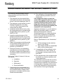
1
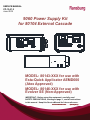
SERVICE MANUAL
CP-13-01.2
June-2014
9060 Power Supply Kit
for 80104 External Cascade
MODEL: 80143-XXX for use with
Esta-Quick Applicator AEMD600
(Atex Approved)
MODEL: 80146-XXX for use with
Evolver SE (Non-Approved)
IMPORTANT: Before using this equipment, carefully read
SAFETY PRECAUTIONS, starting on page 1, and all instructions
in this manual. Keep this Service Manual for future reference.
Service Manual Price:
$50.00 (U.S.)
CP-13-01.2
9060 Power Supply Kit - Contents
CONTENTS
SAFETY:
PAGE
1-6
SAFETY PRECAUTIONS ......................................................................................................... 1
HAZARDS / SAFEGUARDS................................................................................................... 2-6
INTRODUCTION:
8-15
GENERAL DESCRIPTION ........................................................................................................ 8
THE RANSBURG SPRAY PROCESS ...................................................................................... 8
9060 CASCADE LOW VOLTAGE CONTROL UNIT KIT ........................................................... 8
9060 CASCADE LOW VOLTAGE CONTROL UNIT KIT 80143 AND 80146 ............................. 8
9060 LOW VOLTAGE CONTROL UNIT KIT PART STRUCTURE ............................................ 9
SPECIFICATIONS .................................................................................................................. 10
CASCADE CONTROL UNIT FEATURES .......................................................................... 11-13
EUROPEAN ATEX DIRECTIVE 94/9/EC, ANNEX II, 1.0.6 ................................................ 14-15
INSTALLATION:
16-20
TYPICAL INSTALLATION 80143-XXX .................................................................................... 17
HIGH VOLTAGE CABLE A10560-XXD ................................................................................... 18
LOW VOLTAGE CABLE 79338-XX ......................................................................................... 18
HIGH VOLTAGE CABLE TO CASCADE CONNECTION3333333333333333 19
OPERATION:
21
MAINTENANCE:
22
SPARE PARTS
23
WARRANTY POLICIES:
24
LIMITED WARRANTY............................................................................................................. 24
CP-13-01.2
9060 Power Supply Kit - Safety
SAFETY
SAFETY PRECAUTIONS
Before operating, maintaining or servicing any
Ransburg electrostatic coating system, read
and understand all of the technical and safety
literature for your Ransburg products. This
manual contains information that is important
for you to know and understand. This information relates to USER SAFETY and PREVENTING EQUIPMENT PROBLEMS. To help
you recognize this information, we use the following symbols. Please pay particular attention
to these sections.
A WARNING! states information to alert you
to a situation that might cause serious injury if instructions are not followed.
A CAUTION! states information that tells
how to prevent damage to equipment or
how to avoid a situation that might cause
minor injury.
A NOTE is information relevant to the procedure in progress.
While this manual lists standard specifications
and service procedures, some minor deviations may be found between this literature and
your equipment. Differences in local codes and
plant requirements, material delivery requirements, etc., make such variations inevitable.
Compare this manual with your system installation drawings and appropriate Ransburg
equipment manuals to reconcile such differences.
!
WARNING
The user MUST read and be familiar
with the Safety Section in this manual and
the Ransburg safety literature therein
identified.
This manual MUST be read and thor-
oughly understood by ALL personnel who
operate, clean or maintain this equipment!
Special care should be taken to ensure that
the WARNINGS and safety requirements
for operating and servicing the equipment
are followed. The user should be aware of
and adhere to ALL local building and fire
codes and ordinances as well as NFPA-33
SAFETY STANDARD, LATEST EDITION,
prior to installing, operating, and/or servicing this equipment.
!
WARNING
The hazards shown on the following
pages may occur during the normal use
of this equipment. Please read the hazard chart beginning on page 2.
Careful study and continued use of this manual
will provide a better understanding of the
equipment and process, resulting in more efficient operation, longer trouble-free service and
faster, easier troubleshooting. If you do not
have the manuals and safety literature for your
Ransburg system,
contact
your local
Ransburg representative or Ransburg.
1
CP-13-01.2
9060 Power Supply Kit - Safety
AREA
HAZARD
SAFEGUARDS
Tells where hazards may occur.
Tells what the hazard is.
Tells how to avoid the hazard.
Spray Area
Fire Hazard
Fire extinguishing equipment must be present in
the spray area and tested periodically.
Improper or inadequate operation and maintenance proce- Spray areas must be kept clean to prevent the accumulation of combustible residues.
dures will cause a fire hazard.
Protection against inadvertent Smoking must never be allowed in the spray area.
arcing that is capable of causing The high voltage supplied to the atomizer must be
fire or explosion is lost if any turned off prior to cleaning, flushing or maintesafety interlocks are disabled nance.
during operation. Frequent Power Supply or Controller shut- When using solvents for cleaning:
down indicates a problem in the • Those used for equipment flushing should
system requiring correction.
have flash points equal to or higher than those
of the coating material.
•
Those solvents used for cleaning must have a
flash point at minimum of 5oC (9oF) greater
than the ambient temperature. It is the end
users responsibility to insure this condition is
met.).
Spray booth ventilation must be kept at the rates
required by NFPA-33, OSHA, country, and local
codes. In addition, ventilation must be maintained during cleaning operations using flammable
or combustible solvents.
Electrostatic arcing must be prevented. Safe
sparking distance must be maintained between the
parts being coated and the applicator. A distance
of 1 inch for every 10KV of output voltage is required at all times.
Test only in areas free of combustible material.
Testing may require high voltage to be on, but only
as instructed.
Non-factory replacement parts or unauthorized
equipment modifications may cause fire or injury.
If used, the key switch bypass is intended for use
only during setup operations. Production should
never be done with safety interlocks disabled.
Never use equipment intended for use in waterborne installations to spray solvent based materials.
The paint process and equipment should be set up
and operated in accordance with NFPA-33, NEC,
OSHA, local, country, and European Health and
Safety Norms.
CP-13-01.2
2
9060 Power Supply Kit - Safety
AREA
HAZARD
SAFEGUARDS
Tells where hazards may occur.
Tells what the hazard is.
Tells how to avoid the hazard.
Spray Area
Explosion Hazard
Electrostatic arcing must be prevented. Safe
Improper or inadequate opera- sparking distance must be maintained between the
tion and maintenance proce- parts being coated and the applicator. A distance
dures will cause a fire hazard.
of 1 inch for every 10KV of output voltage is reProtection against inadvertent quired at all times.
arcing that is capable of causing
fire or explosion is lost if any Unless specifically approved for use in hazardous
safety interlocks are disabled locations, all electrical equipment must be located
outside Class I or II, Division 1 or 2 hazardous
during operation.
areas, in accordance with NFPA-33.
Frequent Power Supply or Controller shutdown indicates a Test only in areas free of flammable or combusproblem in the system requiring tible materials.
correction.
The current overload sensitivity (if equipped)
MUST be set as described in the corresponding
section of the equipment manual. Protection
against inadvertent arcing that is capable of
causing fire or explosion is lost if the current overload sensitivity is not properly set. Frequent
power supply shutdown indicates a problem in the
system which requires correction.
Always turn the control panel power off prior to
flushing, cleaning, or working on spray system
equipment.
Before turning high voltage on, make sure no objects are within the safe sparking distance.
Ensure that the control panel is interlocked with the
ventilation system and conveyor in accordance
with NFPA-33, EN 50176.
Have fire extinguishing equipment readily available
and tested periodically.
General Use and
Maintenance
Improper operation or mainte- Personnel must be given training in accordance
nance may create a hazard.
with the requirements of NFPA-33, EN 60079-0.
Personnel must be properly Instructions and safety precautions must be read
trained in the use of this equip- and understood prior to using this equipment.
ment.
Comply with appropriate local, state, and national
codes governing ventilation, fire protection, operation maintenance, and housekeeping. Reference
OSHA, NFPA-33, EN Norms and your insurance
company requirements.
3
CP-13-01.2
9060 Power Supply Kit - Safety
AREA
HAZARD
SAFEGUARDS
Tells where hazards may occur.
Tells what the hazard is.
Tells how to avoid the hazard.
Spray Area / High Electrical Discharge
Voltage Equipment
There is a high voltage device
Parts being sprayed and operators in the spray
area must be properly grounded.
that can induce an electrical
charge on ungrounded objects
Parts being sprayed must be supported on conveywhich is capable of igniting coat- ors or hangers that are properly grounded. The
ing materials.
resistance between the part and earth ground must
not exceed 1 meg ohm. (Refer to NFPA-33.)
Inadequate grounding will cause
a spark hazard. A spark can
Operators must be grounded. Rubber soled insuignite many coating materials
lating shoes should not be worn. Grounding straps
and cause a fire or explosion.
on wrists or legs may be used to assure adequate
ground contact.
Operators must not be wearing or carrying any
ungrounded metal objects.
When using an electrostatic handgun, operators
must assure contact with the handle of the applicator via conductive gloves or gloves with the palm
section cut out.
NOTE: REFER TO NFPA-33 OR SPECIFIC
COUNTRY SAFETY CODES REGARDING
PROPER OPERATOR GROUNDING.
All electrically conductive objects in the spray area,
with the exception of those objects required by the
process to be at high voltage, must be grounded.
Grounded conductive flooring must be provided in
the spray area.
Always turn off the power supply prior to flushing,
cleaning, or working on spray system equipment.
Unless specifically approved for use in hazardous
locations, all electrical equipment must be located
outside Class I or II, Division 1 or 2 hazardous
areas, in accordance with NFPA-33.
CP-13-01.2
4
9060 Power Supply Kit - Safety
AREA
HAZARD
SAFEGUARDS
Tells where hazards may occur.
Tells what the hazard is.
Tells how to avoid the hazard.
Electrical
Equipment
Electrical Discharge
High voltage equipment is utilized in the process. Arcing in
the vicinity of flammable or
combustible materials may occur. Personnel are exposed to
high voltage during operation
and maintenance.
Unless specifically approved for use in hazardous
locations, the power supply, control cabinet, and all
other electrical equipment must be located outside
Class I or II, Division 1 and 2 hazardous areas in
accordance with NFPA-33 and EN 50176.
Turn the power supply OFF before working on the
Protection against inadvertent equipment.
arcing that may cause a fire or
explosion is lost if safety circuits Test only in areas free of flammable or combustible material.
are disabled during operation.
Frequent power supply shut- Testing may require high voltage to be on, but only
down indicates a problem in the as instructed.
system which requires correcProduction should never be done with the safety
tion.
circuits disabled.
An electrical arc can ignite coating materials and cause a fire or Before turning the high voltage on, make sure no
objects are within the sparking distance.
explosion.
Toxic Substances
Chemical Hazard
Follow the requirements of the Material Safety
Certain materials may be harm- Data Sheet supplied by coating material manufacful if inhaled, or if there is con- turer.
tact with the skin.
Adequate exhaust must be provided to keep the
air free of accumulations of toxic materials.
Use a mask or respirator whenever there is a
chance of inhaling sprayed materials. The mask
must be compatible with the material being
sprayed and its concentration. Equipment must be
as prescribed by an industrial hygienist or safety
expert, and be NIOSH approved.
5
CP-13-01.2
9060 Power Supply Kit - Safety
AREA
HAZARD
SAFEGUARDS
Tells where hazards may occur.
Tells what the hazard is.
Tells how to avoid the hazard.
Spray Area
Explosion Hazard—
Incompatible Materials
Halogenated hydrocarbon solvents for example: methylene
chloride and 1,1,1,Trichloroethane are not chemically compatible with the aluminum that might be used in many
system components. The
chemical reaction caused by
these solvents reacting with aluminum can become violent and
lead to an equipment explosion.
CP-13-01.2
Aluminum is widely used in other spray application
equipment - such as material pumps, regulators,
triggering valves, etc. Halogenated hydrocarbon
solvents must never be used with aluminum equipment during spraying, flushing, or cleaning. Read
the label or data sheet for the material you intend
to spray. If in doubt as to whether or not a coating
or cleaning material is compatible, contact your
coating supplier. Any other type of solvent may be
used with aluminum equipment.
6
9060 Power Supply Kit - Introduction
NOTES
7
CP-13-01.2
9060 Power Supply Kit - Introduction
INTRODUCTION
GENERAL DESCRIPTION
The Ransburg Spray Process
The Ransburg Spray Process is an air atomized method for applying coatings to objects
electrostatically. This system applies a high
voltage DC charge to the applicator nozzle
electrode, creating an electrostatic field
between the atomizer and the target object.
The target is electrically grounded through its
support that may be either stationary or
moving.
A regulated pressure fluid system delivers
coating material to the atomizer. At the
atomizer, air is applied that atomizes the
coating material forming a spray mist that,
under the influence of the electrostatic field,
becomes electrically charged. The charged
particles are attracted to, and deposited on,
the target object. The forces between the
charged particles and the grounded target are
sufficient to turn most normal overspray
around and deposit it on the side and back
surfaces of the target. Therefore, a high
percentage of the spray is deposited on the
target.
operating current to a safe maximum value.
In addition to supplying low voltage output to
the applicator, the 9060 Cascade control unit
also provides controls for AC power ON/
OFF, infinite high voltage adjustment, a high
voltage meter, a current meter, an AC power
ON indicator, a high voltage ON indicator, a
cable fault indicator, and a current overload
indicator and reset switch. Additionally,
output terminals are provided for remote
overload reset, analog current output, and
high voltage control. Interlock connections
for a conveyor and exhaust fan are also
provided. A combination triple setpoint/
analog input control board is also supplied
with 9060 Cascade control units powering
automatic spray applicators.
9060 Power Supply Kit
80143 and 80146
The 9060 Power Supply Kit 80143-XXX and
80146-XXX are designed to be used with
either the Esta-Quick Applicator (AEMD 600)
or the Evolver SE product (A12455-XXXX).
Both use an oil filled cascade.
9060 Power Supply
The 9060 Cascade Control Unit converts
standard AC line voltage to a high frequency,
low voltage signal ranging from 0 to 10 Vrms.
This signal is supplied to an external cascade
through a low voltage cable. The external
cascade converts the low voltage signal into a
high voltage. This high voltage is transmitted
through the cable to the applicator. At the
applicator an electrode in the applicator
creates a DC high voltage field the spray goes
through and picks up the electrostatic charge.
When the material is directed to a grounded
target, more material is attracted to the target
yielding higher painting efficiency.
The voltage/current characteristic is designed
to optimize the charging process under
varying load conditions, and to limit the
CP-13-01.2
NOTE
The only combination of units that carry
any approval is the AEMD600 used with the
80143-XXX units as described in this manual.
Any other combination of applicator and 9060
unit does not have any agency approval associated with it. When using equipment that
is not approved, the user needs to be aware
of the code requirements needed to operate
safely. If there is any question regarding safe
installation requirements when using this
product, refer to European Norms (EN 50
176) or NFPA-33.
8
9060 Power Supply Kit - Introduction
The 9060 Power Supply Kit is available for automatic applicators as follows:
**Note: CE/Atex approval with this power source is only for the AEMD-600
**9060 Power Supply Kit Part Structure
80143-ABC (Atex approved when used with AEMD600)-Esta-Quick
A-Unit Power Type
-1 For 110/120 V Input Power (Domestic) 10” Rack
-2 For 220/240 V Input Power (European) 10”Rack
-3 For 220/240 V Input Power (Chinese) 10” Rack
-4 For 110/120 V Input Power (Domestic) Box Style
-5 For 220/240 V Input Power (European) Box Style
-6 For 220/240 V Input Power (Chinese) Box Style
B- High Voltage Cable Length
-1 For 4.5 m (15 ft.)
-2 For 7.5 m (25 ft.)
-3 For 15 m (50 ft.)
-4 For 22.5m (75 ft.)
C-Low Voltage Cable Length
-1 10 m LV Cable
-2 15 m LV Cable
80146-ABC (non- approved when used with A12455-XX) Evolver SE
A-Unit Power Type
-1 For 110/120 V Input Power (Domestic) 10” Rack
-2 For 220/240 V Input Power (European) 10”Rack
-3 For 220/240 V Input Power (Chinese) 10” Rack
-4 For 110/120 V Input Power (Domestic) Box Style
-5 For 220/240 V Input Power (European) Box Style
-6 For 220/240 V Input Power (Chinese) Box Style
B- High Voltage Cable Length
-1 For 4.5 m (15 ft.)
-2 For 7.5 m (25 ft.)
-3 For 15 m (50 ft.)
-4 For 22.5m (75 ft.)
C-Low Voltage Cable Length
-1 10 m LV Cable
-2 15 m LV Cable
9
CP-13-01.2
9060 Power Supply Kit - Introduction
SPECIFICATIONS
Physical - #80143 Kit - 10” Rack
9060 P/N 80120-31X
Input:
Voltage:
90-264 VAC
429mm (16.9 inches)
(483mm ear to ear)
(19 inches)
Current:
0.4/0.2 Amps AC
308mm (12.1 inches)
Wattage:
40 watts (Max.)
6.8 kg (15.1 lbs.)
Output:
Voltage:
0-10 VRMS
Current:
1.5 Amps RMS (max.)
Height:
132mm (5.2 inches)
Width:
Depth:
Weight:
Physical - #80143 Kit - 19” Box
9060 P/N 80100-31X
Height:
16.5 cm (6.5 inches)
Width:
37.8 cm (14.9 inches)
Depth:
30.7 cm (12.1 inches)
Weight:
Electrical Requirements
10.2 kg (22.5 lbs.)
Frequency:
Pneumatic:
Supply Air:
Cascade:
Umax:
Max. Current:
50/60 Hertz
6.9 Bar (Max.) (100 PSI)
90kv (Maxi.)
120 mA (Max.)
Physical - Cascade—#80104
Height:
Width:
Weight:
CP-13-01.2
400mm (15.7 inches)
102mm Square (4.0 inches)
4.1 kg (9.1 lbs.)
10
9060 Power Supply Kit - Introduction
Number
1
2
3
4
5
6
7
8
9
10
11
12
Description
Kilovolt Display
Micro Amp Display
High Voltage On Indicator
Unit—OFF—OFF Switch
Set Point Adjust Buttons
Fault Indicator
Manual Reset Pad
External Wiring Grommet
Fuse
Low Voltage Cable Connector
AC Inlet Receptacle
Ground Wire Assembly
Figure 1: 80100 Cascade Control Unit Features
11
CP-13-01.2
9060 Power Supply Kit - Introduction
Number
1
2
3
4
5
6
7
8
9
10
11
12
Description
Kilovolt Display
Micro Amp Display
High Voltage On Indicator
Unit—OFF—OFF Switch
Set Point Adjust Buttons
Fault Indicator
Manual Reset Pad
External Wiring Grommet
Fuse
Low Voltage Cable Connector
AC Inlet Receptacle
Ground Wire Assembly
Figure 2: 80120 Cascade Control Unit Features
CP-13-01.2
12
9060 Power Supply Kit - Introduction
Number
1
2
3
4
Description
Low Voltage Cable Connector
Ground Lug Connector
Cascade High Voltage Connection
Ground Wire Assembly
Figure 3: 80104 Cascade Control Unit Features
13
CP-13-01.2
9060 Power Supply Kit - Introduction
EUROPEAN ATEX DIRECTIVE 94/9/EC, ANNEX II, 1.0.6
The following instructions apply to equipment covered by certificate number Sira
11ATEX5240X:
8. The certification of this equipment relies
upon the following materials used in its
construction:
1. The equipment may be used with flammable gases and vapors with apparatus
groups II and with temperature class T6.
If the equipment is likely to come into
contact with aggressive substances, then
it is the responsibility of the user to take
suitable precautions that prevent it from
being adversely affected, thus ensuring
that the type of protection provided by the
equipment is not compromised.
2. The equipment is only certified for use in
ambient temperatures in the range
+12.8oC to +40oC and should not be
used outside this range.
3. Installation shall be carried out by suitably trained personnel in accordance with
the applicable code of practice e.g. EN
60079-14:1997.
4. Inspection and maintenance of this
equipment shall be carried out by suitably trained personnel in accordance with
the applicable code of practice e.g. EN
60079-17.
5. Repair of this equipment shall be carried
out by suitable trained personnel in accordance with the applicable code of
practice e.g. EN 60079-19.
Aggressive substances: e.g. acidic liquids or
gases that may attack metals, or solvents
that may affect polymeric materials.
Suitable precautions: e.g. regular checks as
part of routine inspections or establishing
from the material's data sheets that it is resistant to specific chemicals.
Refer to "Specifications" in the "Introduction"
section:
a. All fluid passages contain stainless
steel or nylon fittings.
b. High voltage cascade is encapsulated
with a solvent resistant epoxy.
6. Putting into service, use, assembling,
and adjustment of the equipment shall
be fitted by suitably trained personnel in
accordance with the manufacturer's documentation.
9. A recapitulation of the certification marking is detailed in the "Atex" section, on
the next page, drawing numbers: 80108
and 80075.
Refer to the "Table of Contents" of this service manual:
10. The characteristics of the equipment shall
be detailed e.g. electrical, pressure, and
voltage parameters.
a. Installation
b. Operation
c. Maintenance
d. Parts Identification
7. Components to be incorporated into or
used as replacement parts of the equipment shall be fitted by suitably trained
personnel in accordance with the manufacturer's documentation.
CP-13-01.2
The manufacturer should note that, on being
put into service, the equipment must be accompanied by a translation of the instructions
in the language or languages of the country
in which the equipment is to be used and by
the instructions in the original language.
14
9060 Power Supply Kit - Installation
9060 Cascade Low Voltage
Control Unit Kit ATEX Product 80143-XXX
Marking Definitions
Ex Certificate Number: Sira 11ATEX5240X
Sira = Notified Body performing EC-type
examination
11 = Year of certification
ATEX = Reference to ATEX Directive
5 = Protection Concept Code (code 5 is
titled Encapsulation)
240 = Document serial number
X = Special conditions for safe use apply
Label 80108
Product Marking
II 2 G
Ex = Specific marking of explosive protection
II = Equipment Group hazardous area
characteristics
2 = Equipment Category
G = Type of explosive atmosphere
(gases, vapors, or mists)
Label 80075
EEx 0.24mJ. The 80143-XXX 9060 Cascade Control Unit Kit is suitable for use in
electrostatic spraying installations complying with EN 50 176 as they are a Type
A class with a discharge energy limit of
0.24mJ.
Label 80081
15
CP-13-01.2
9060 Power Supply Kit - Installation
INSTALLATION
!
WARNING
The 9060 Controller MUST be located
outside of the hazardous area.
The User MUST read and be familiar
with the “Safety” section of this manual.
This manual MUST be read and thoroughly understood by ALL personnel who
operate, clean, or maintain this equipment!
Special care should be taken to ensure that
the warnings and requirements of operating
and servicing safely are followed. The user
should be aware of and adhere to ALL local
building and fire codes and ordinances as
well as NFPA-33, OSHA, and all related
country safety codes prior to installing, operating, and/or servicing this equipment.
Refer to CP-13-05 or CP-13
-02 (Included with Your Kit)
for Control Unit Installation
Instructions.
CP-13-01.2
16
9060 Power Supply Kit - Installation
10” VERSION 80120-X1X
19” VERSION 80100-X1X
Number
Description
1
9060 Low Voltage Unit
2
AEMD-600 Unit (Atex Approved) WITH
MACHINE ADAPTER AEMD-4500-6
3
4
5
6
7
A10560-XXD High Voltage Cable
80104-01 External Cascade
79338-XX Low Voltage Cable
Booth Wall
Cascade Ground Connection
8
Cascade Separate True Earth Ground
9
Control Unit Separate True Earth Ground
Figure 4: Typical Installation 80143-XXX
17
CP-13-01.2
9060 Power Supply Kit - Installation
Cascade Ground Connection
Cascade End
Applicator End
Figure 5: High Voltage Cable A10560-XXD
Connection-Cascade End
Connection-Control Unit End
Figure 6: Low Voltage Cable 79338-XX
CP-13-01.2
18
9060 Power Supply Kit - Introduction
HIGH VOLTAGE CABLE TO CASCADE CONNECTION
Strain Relief
Insert the grounded cable end of the high voltage cable and the associated connector
parts into the external cascade in the order shown.
Before tightening the cable strain relief, assure the cable is fully inserted and seated into
the bottom of the high voltage tube.
19
CP-13-01.2
9060 Power Supply Kit - Introduction
CP-13-01.2
20
9060 Power Supply Kit - Operation
OPERATION
!
WARNING
The user MUST read and be familiar
with the SAFETY PRECAUTIONS and
SAFETY SECTIONS of this manual and
the Ransburg safety literature therein
identified BEFORE OPERATING the
9060 Cascade control unit.
Refer to CP-13-02 or CP-13
-05 (Included in Your kit) for
Operation Instructions and
Procedures.
21
CP-13-01.2
9060 Power Supply Kit - Operation
MAINTENANCE
Consult CP-13-02 or CP-13
-05 (Included in Your kit) for
Maintenance and Trouble
Shooting Information.
CP-13-01.2
22
9060 Power Supply Kit - Warranty Policies
Spare Parts
Refer to CP-13-02 or CP-13
-05 (Included in Your kit) for
Spare parts available.
80104-01 EXTERNAL CASCADE COMPONENTS
Item #
Part Number
Description
1*
80074-00
COUPLER, CABLE
2*
3*
4*
7296-00
80073-00
8521-06F
NUT, CABLE PLUG
RELIEF, STRAIN
SET SCREW
5
80104-01
ASSEMBLY, EXTERNAL (includes item 6)
6
79350-01
SUB-ASSEMBLY, CASCADE
*Not included with the 80104-01 Assembly (must be ordered separately)
23
CP-13-01.2
9060 Power Supply Kit - Warranty Policies
WARRANTY POLICIES
LIMITED WARRANTY
Ransburg will replace or repair without charge
any part and/or equipment that falls within the
specified time (see below) because of faulty
workmanship or material, provided that the
equipment has been used and maintained in
accordance with Ransburg's written safety and
operating instructions, and has been used
under normal operating conditions. Normal
wear items are excluded.
THE USE OF OTHER THAN RANSBURG
APPROVED PARTS, VOID ALL WARRANTIES.
SPARE PARTS: One hundred and eighty (180)
days from date of purchase, except for rebuilt
parts (any part number ending in "R") for which
the warranty period is ninety (90) days.
EQUIPMENT: When purchased as a complete
unit, (i.e., guns, power supplies, control units,
etc.), is one (1) year from date of purchase.
RANSBURG'S ONLY OBLIGATION
UNDER THIS WARRANTY IS TO REPLACE PARTS THAT HAVE FAILED
BECAUSE OF FAULTY WORKMANSHIP
OR MATER-IALS. THERE ARE NO
IMPLIED WAR-RANTIES NOR WARRANTIES OF EITHER MERCHANTABILITY OR
FITNESS FOR A PARTICULAR PURPOSE.
RANS-BURG ASSUMES NO LIABILITY
FOR INJURY, DAMAGE TO PROPERTY
OR FOR CONSEQUENTIAL DAMAGES
FOR LOSS OF GOODWILL OR PRODUCTION OR INCOME, WHICH RESULT FROM
USE OR MISUSE OF THE EQUIPMENT BY
PURCHASER OR OTHERS.
EXCLUSIONS:
If, in Ransburg's opinion the warranty item in
question, or other items damaged by this
part was improperly installed, operated or
maintained, Ransburg will assume no
responsibility for repair or replacement of the
item or items. The purchaser, therefore will
assume all responsibility for any cost of
repair or replacement and service related
costs if applicable.
WRAPPING THE APPLICATOR, ASSOCIATED VALVES AND TUBING, AND
SUPPORTING HARDWARE IN PLASTIC,
SHRINK-WRAP, OR ANY OTHER NONAPPROVED COVERING, WILL VOID THIS
WARRANTY.
CP-13-01.2
24
Manufacturing
1910 North Wayne Street
Angola, Indiana 46703-9100
Telephone: 260-665-8800
Fax: 260-665-8516
Technical Service — Assistance
320 Philips Ave.
Toledo, Ohio 43612-1493
Telephone (toll free): 800-233-3366
Fax: 419-470-2233
Technical Support Representative will direct you to the appropriate telephone number for ordering Spare Parts.
© 2014 Ransburg. All rights reserved.
Models and specifications subject to change without notice.
Litho in U.S.A.
06/14