1
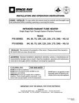
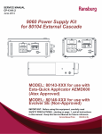
SERVICE MANUAL
LN-9259-07.1
Replaces LN-9259-07
April - 2013
RMA-303 INDIRECT / RMA-303 DIRECT
EVOLVER 303 / EVOLVER NE
TEST STATIONS
CAT DESC
MANUFACTURER
160
CAT
160
TURBINE
S.A.O./FAN
BEARING AIR
S.A.I./ATOM
CAT DESC
MANUFACTURER
DESC
MANUFACTURER
100
100
100
100
100
IMPORTANT: Before using this equipment, carefully read
SAFETY PRECAUTIONS, starting on page 1, and all
instructions in this manual. Keep this Service Manual for
future reference.
Service Manual Price:
$30.00 (U.S.)
LN-9259-07.1
Test Stations - Contents
CONTENTS
PAGE
SAFETY:
1-4
SAFETY PRECAUTIONS............................................................................................................ 1-2
HAZARDS / SAFEGUARDS....................................................................................................... 3-4
INTRODUCTION:
5-8
GENERAL INFORMATION......................................................................................................... 5
SPECIFICATIONS....................................................................................................................... 5
FEATURES.................................................................................................................................. 6-7
OPERATION:
9-20
RMA TEST PROCEDURE..........................................................................................................
INITIAL TEST SETTIN
GS............................................................................................................
TEST TRIGGERS........................................................................................................................
TURBINE TEST.........................................................................................................................
..
9
9-10
11-14
15-16
16-17
17-19
MAINTENANCE:
21-22
MAINTENAN
21
WARRANTY POLICIES:
23
LIMITED WARRANTY................................................................................................................. 23
LN-9259-07.1
Test Stations - Safety
SAFETY
SAFETY PRECAUTIONS
Before operating, maintaining or servicing any
Ransburg electrostatic coating system, read and
understand all of the technical and safety literature for your Ransburg products. This manual
contains information that is important for you to
know and understand. This information relates to
USER SAFETY and PREVENTING EQUIPMENT
PROBLEMS. To help you recognize this information, we use the following symbols. Please pay
particular attention to these sections.
A WARNING! states information to alert you to a
situation that might cause serious injury if instructions are not followed.
A CAUTION! states information that tells how to
prevent damage to equipment or how to avoid a
situation that might cause minor injury.
A NOTE is information relevant to the procedure
in progress.
While this manual lists standard specifications
and service procedures, some minor deviations
may be found between this literature and your
equipment. Differences in local codes and plant
requirements, material delivery requirements,
etc., make such variations inevitable. Compare
this manual with your system installation drawings
and appropriate Ransburg equipment manuals to
reconcile such differences.
WARNING
> The user MUST read and be familiar with
the Safety Section in this manual and the
Ransburg safety literature therein identified.
> This manual MUST be read and thoroughly
understood by ALL personnel who operate,
clean or maintain this equipment! Special
care should be taken to ensure that the
WARNINGS and safety requirements for
operating and servicing the equipment are
followed. The user should be aware of and
adhere to ALL local building and fire codes
and ordinances as well as NFPA-33 SAFETY
STANDARD, prior to installing, operating,
and/or servicing this equipment.
WARNING
> The hazards shown on the following page
may occur during the normal use of this
equipment. Please read the hazard chart
beginning on page 3.
Careful study and continued use of this manual
will provide a better understanding of the equipment and process, resulting in more efficient
operation, longer trouble-free service and faster,
easier troubleshooting. If you do not have the
manuals and safety literature for your Ransburg
system, contact your local Ransburg representative or Ransburg.
1
LN-9259-07.1
Test Stations - Safety
NOTE
NOTES
> The high voltage is interlocked electrically with the fluid trigger switches. When
a fluid switch is triggered on, the HV will
automatically be turned off.
WARNING
> Wear the proper safety protection such as
eye and ear protection.
> NEVER wear loose clothing while working
around the applicator.
> NEVER run the applicator with anyone near
the bell. Serious injury COULD OCCUR if
the bell is contacted while it is rotating.
> NEVER stop the rotation of the bell by
hand. Use the manual air brake supplied
on the test stand panel.
> Ensure ALL items in the test area are
grounded. Ensure there are NO open containers of flammable materials in the test area.
LN-9259-07.1
2
Test Stations - Safety
AREA
Tells where hazards
may occur.
Spray Area
HAZARD
Tells what the hazard is.
Fire Hazard
Improper or inadequate operation and maintenance
procedures will cause a fire
hazard.
Protection against inadvertent arcing that is capable
of causing fire or explosion
is lost if any safey interlocks
are disabled during operation. Frequent power supply
shutdown indicates a problem
SAFEGUARDS
Tells how to avoid the hazard.
Fire extinguishing equipment must be present in
the spray area and tested periodically.
Spray areas must be kept clean to prevent the
accumulation of combustible residues.
Smoking must never be allowed in the spray
area.
The high voltage supplied to the atomizer must
be turned off prior to cleaning, flushing, or maintenance.
When using solvents for cleaning:
Those used for equipment flushing should have
flash points equal to or higher than those of the
coating material.
Those used for general cleaning must have flash
points above 100°F (37.8°C).
Spray booth ventilation must be kept at the rates
required by NFPA 33, OSHA, and local codes. In
addition, ventilation must be maintained during
cleaning operations using flammable or combustible solvents.
Electrostatic arcing must be prevented.
Test only in areas free of combustible material.
Testing may require high voltage to be on, but
only as instructed.
Non-factory replacement parts or unauthorized
equipment modifications may cause fire or injury.
If used, the key switch bypass is intended for use
only during setup operations. Production should
never be done with safety interlocks disabled.
Never use equipment intended for use in waterborne installations to spray solvent based
materials.
The paint process and equipment should be set
up and operated in accordance with NFPA-33,
NEC, and OSHA requirements.
3
LN-9259-07.1
Test Stations - Safety
AREA
Tells where hazards
may occur.
General Use and
Maintenance
HAZARD
Tells what the hazard is.
SAFEGUARDS
Tells how to avoid the hazard.
Improper operation or mainte- Personnel must be given training in accordance
with the requirements of NFPA-33.
nance may create a hazard.
Personnel must be properly Instructions and safety precautions must be read
trained in the use of this equip- and understood prior to using this equipment.
ment.
Comply with appropriate local, state, and national
codes governing ventilation, fire protection, operation maintenance, and housekeeping. Reference
OSHA, NFPA-33, and your insurance company
requirements.
Electrical
Equipment
High voltage equipment is utilized. Arcing in areas of flammable or combustible materials may occur. Personnel are
exposed to high voltage during
operation and maintenance.
The power supply, optional remote control cabinet,
and all other electrical equipment must be located
outside Class I or II, Division 1 and 2 hazardous
areas (refer to NFPA-33).
Turn the power supply OFF before working on
the equipment.
Protection against inadvertent
arcing that may cause a fire Test only in areas free of flammable or combustible
or explosion is lost if safety material.
circuits are disabled during
Testing may require high voltage to be on, but
operation.
only as instructed.
Frequent power supply shutdown indicates a problem in Production should never be done with the safety
the system which requires circuits disabled.
correction.
Before turning the high voltage on, make sure no
An electrical arc can ignite objects are within the sparking distance.
coating materials and cause
a fire or explosion.
LN-9259-07.1
4
Test Stations - Introduction
INTRODUCTION
GENERAL INFORMATION
specifications
The Ransburg Applicator Performance Test Stand
was developed to assist in determining the applicator’s level of performance in an off-line condition. (Ensuring the applicator functions properly
after any maintenance has been performed to it
and reduces the costs associated with verifying
performance during production.) With line speeds
critical to the through-put of a facility, every uptime
minute counts to underwrite profitability. This
Test Stand device helps to ensure the applicator
performs correctly when it is put into service.
Electrical / Physical
This Test Stand will verify performance of single
or dual fluid applicators, bearing air, shaping air,
brake air, turbine drive air, and fiber optic functionality. As well, it checks kV and µA electrical
performance of the applicator.
1-inch NPT(F) Inlet
Air Requirements:
3/4-inch ID Air Line to Stand
100 psi (6.4 bar) minimum
30 SCFM
0.3 to 0.6 Micron Filtration
Dimensions
Height: 67-inch (1702cm)
Width:
30-inch (762cm)
Length:
48-inch (1219cm)
Fluids:
Use distilled or deionized water only for testing.
Maximum Fluid
Pressure:
80 psi (5.2 bar)
The Test Stand was developed with the user and
the safety of the user in mind. The user must
become familiar with the overall function and
operation of the unit.
NOTE
> For all test station toggle switches, with the
switch lever in the “UP” position, the valve it
describes is “ON” or “actuated.”
5
LN-9259-07.1
Test Stations - Introduction
FEATURES
CAT DE SC
MANUF ACTURER
160
160
TURBINE
S.A.O./FAN
BEARING AIR
S.A.I./ATOM
CAT DE SC
MANUF ACTURER
100
100
100
100
100
1 Main Control Panel
5 Pressure Pot
2 Air Flow Meters
6 Dump Bucket
3 Test Applicator
7 High Voltage Cascade
4 Table
8 Air Filter
Figure 1a: Basic Station Features
LN-9259-07.1
6
Test Stations - Introduction
CAT
DESC
MANUF ACTURER
160
160
CAT
CAT
DESC
TURBINE
S.A.O./FAN
BEARING AIR
S.A.I./ATOM
DESC
MANUF ACTURER
MANUF ACTURER
100
100
100
100
100
1 Power Control - On/Off Button
9
2 Main Air Gauges - Leak Down, Supply Air
10 Atomizer Card
3 Fiber Optic Voltage Readout
11 MicroPak Power Supply
4 Air Flow Meter - Atom Air
12 Applicator Enable, Paint Trigger, Cup Wash Solvent, Cup Wash Air, Dump
5 Air Flow Meter - Outer Shaping Air
Atomizer Speed Select Card
6 Air Flow Meter - Bearing Air
13 Regulated Function Gauges - Bearing Air, Outer Shaping Air, Inner Shaping Air
7 Air Flow Meter - Inner Shaping Air
14 High Voltage - On/Off Switch
8 Fluid Enable - Paint In, Cup Wash Solvent
In, Cup Wash Air In
Figure 1b: Basic Station Features
7
LN-9259-07.1
Test Stations - Introduction
NOTES
LN-9259-07.1
8
Test Stations - Operation
OPERATION
rma TEST PROCEDURE
WARNING
> NEVER use solvent as a test fluid for this
device!
Setup
NOTE
> Refer to the applicator service manual
for all parts and part number identifications.
1. Ensure that ground connections, cart ground,
and applicator ground are made to a true earth
ground.
WARNING
> If true earth ground is not made, injury
to personnel or serious damage may occur
to the equipment.
> Ensure ALL items in the test area are
grounded. Ensure there are NO open
containers of flammable materials in the
test area.
2. Provide air filtration to the manifold that has
the capability of passing 30 SCFM with particulate
removal of .3 to .6 micron particle size (bearing
air filtration is provided with the stand).
3. Provide a minimum 3/4-inch ID air line to the
filter at the manifold inlet. A minimum of 100 psig
pressure is required at the manifold inlet.
> Using any material OTHER than distilled
water or de-ionized water may cause fire
during the test. Use only distilled water or
de-ionized to test the applicator.
5. Fill the pressure pot liner with approximately
one (1) gallon of either de-ionized or distilled
water.
6. Plug the unit into a suitable 110/120V outlet.
NOTE
> When opening dump valve for any test,
hold tubing securely by hand or clamp to
prevent whipping.
Initial Test Settings
1. High voltage is off unless instructed to turn on.
Main power off.
4. Install water supply line and air pressure line
to the pressure pot.
9
LN-9259-07.1
Test Stations - Operation
2. Fluid enable off (toggle switch lever in the
down position).
7. Adjust bearing air regulator to 90 psig minimum.
100
3. Attach the applicator to the Test Stand bracket
with three (3) M10 screws (78268-00).
4. Connect tubing from the Test Stand to the applicator as labeled.
5. Supply 100 psig air pressure to the stand,
reference supply air gauge on panel. If required,
adjust air input regulator attached to stand.
6. Set speed select to 00.
LN-9259-07.1
10
Test Stations - Operation
TEST TRIGGERS
1. Ensure fluid supply is OFF.
5. Toggle on the “Dump” switch; air should be
escaping from the “Dump Port” of the applicator.
Turn off the “Dump” switch.
2. Turn “fluid” switch to AIR.
3. Toggle the “Paint Fluid Enable” switch on (up)
to supply air pressure to the applicator.
6. Toggle “Paint Fluid Enable” switch to the off
(down) position.
4. Toggle on the “Paint Trigger” switch; air should
be escaping from the feed tube. Turn off the
“Paint Trigger”.
7. Turn on the “Cup Wash Air” switch, now turn on
the “Bell Solvent” trigger, air should be escaping
from the feed tube and cup wash spout. Turn off
the “Cup Wash Air” trigger and the “Cup Wash
Air In” switch.
8. Turn on the “Cup Wash Solvent” switch, air
should be escaping from the feed tube and cup
wash spout. Turn off the “Cup Wash Solvent” and
“Cup Wash Solvent In”.
11
LN-9259-07.1
Test Stations - Operation
Air Test
1. Turn the “Fluid” switch to “Air” then “Off” to
pressurize the system.
4. Turn the “Fluid Air” regulator to 0 psig. Open
the manual relief valve on the pressure pot. Turn
all switches off. Ensure “Fluid Enable” switches
are all off.
100
2. Observe the leak test gauge. The pressure
must not drop more than 2 psi in 10 seconds.
160
3. Open the “Dump” to de-pressurize the system
and turn off all of the trigger valves. Switch the
“Dump” to “Off”
Static Decay / Water
Pressure Test
The purpose of this test is to verify that each of the
valves in the applicator will pass fluid. Also, this
test verifies all seals along the fluid passages have
been properly installed to prevent any leakage.
1. Ensure all toggle switches are set to the “off”
or “down” position.
2. Position the applicator where any water
sprayed out of the bell may be collected and
properly disposed of.
3. Verify there is no residual pressure in the
pressure pot included with the test stand. Turn
the regulator dial on the pressure pot counterclockwise until all pressure is released. Pull the
bleed-off valve to release any remaining pressure.
LN-9259-07.1
12
Test Stations - Operation
5. Close the lid, tighten the lid clamps so that the
lid is secure and no air pressure may escape.
WARNING
> Never use solvent as a test fluid for
this device.
6. Turn the “Fluid” switch to “Water” position.
4. Loosen the pressure pot clamps until the lid
may be removed from the pot. Fill the pressure
pot with de-ionized or distilled water.
7. Turn the “Fluid Air” regulator to the pressure
pot to 80 psi.
8. Make sure the dump line is secured in the bucket and the dump valve is in the “Open” position.
9. Turn on “Paint Fluid Enable” and cup wash
“Solvent Fluid Enable” in the Fluid Enable section.
13
LN-9259-07.1
Test Stations - Operation
10. Activate the “dump” trigger until the air is
completely purged from the manifold. You will see
water running from the dump output. Turn the
“Dump” switch off which will stop the water flow.
Turn “Fluid” switch to “off”. Leak gauge should
stay at pressure.
11. Observe the applicator for any possible water
leakage, wait 3 minutes. No seepage is allowed.
12. If leak is found, turn the “Fluid” switch to “Air”
and activate the dump until all water is evacuated. Turn “Fluid” switch to “Off”. Repair leak
and repeat the test.
adjusted to 100 psi input pressure.
4. Readjust the shaping air dial to 25 psi. Reference shaping air gauge for the correct pressure
reading.
5. Look at the shaping air flow meter. It should
be reading 4-7 CFM (outer) and 4-7 CFM (inner).
Make sure the flow meter regulator is adjusted to
100 psi input pressure.
6. Turn off the “Shaping Air” dial.
13. If no leak is found, turn the “Fluid” switch to
“Air”. Open the dump to purge out the water.
14. When all water has been evacuated, close
the dump, turn off all switches and turn the “Fluid”
switch to “Off”.
TURBINE
S.A.O./FAN
BEARING AIR
S.A.I./ATOM
Shaping Air Consumption Test (Inner and
Outer)
1. Reduce the turbine speed from 70k to 30k rpm.
2. Turn on the “Shaping Air” dial and adjust the
outer shaping air to 60 psi. Reference the shaping
air gauge for the correct pressure reading. Ensure
no air leak is present between the shaping air cap
and shroud. If present, inspect the assembly.
3. Look at the shaping air flow meter. It should
be reading 10-13 CFM (outer) and 10-13 CFM
(inner). Make sure the flow meter regulator is
100
LN-9259-07.1
100
14
Test Stations - Operation
TURBINE TEST
4. Set the atomizer speed select to 30,000 rpm.
The purpose of this test is to verify the applicator rotates properly and sprays reasonably well.
With de-ionized or distilled water as the test fluid
it is difficult to accurately assess the spray performance characteristics. However, it can give a
relative indication of how well the bell will spray
in production.
5. Toggle “Enable 1” “On” or in the “Up” position
on the atomizer speed select card. Then press
the “Speed Enter” button. The turbine should now
begin spinning. This should be audible.
NOTE
> Bell cup and shroud must be attached
to end of turbine.
Bearing Air / Drive Air Test
This test is to verify the applicator responds to
changes in setpoints in the speed selector.
1. Raise the safety spin guard and lock it in place
with the pin.
6. Adjust the speed select to 50,000 rpm. Press
the “Speed Enter” button to enter the new speed.
An audible difference in speed should be detected. Adjust the speed again to 70,000 rpm
and press “Speed Enter” to enter the new speed.
7. Observe the atomizing air gauge. At 70,000
rpm the air consumption should not exceed 17.0
SCFM.
Brake Test
1. Re-adjust the turbine speed select card to
70k rpm.
2. Set the atomizer speed card to 1k rpm. (Do not
activate this speed until the next step.)
15
2. Adjust the air regulator for bearing air to 90
psig minimum.
3. Using a stop watch to time the brake speed,
press the atomizer speed card button and watch
the time it takes for the applicator to reach 1k rpm.
3. The turbine shaft must rotate freely with bearing air supplied.
4. Brake time should NOT exceed 14 seconds.
LN-9259-07.1
Test Stations - Operation
Fiber Optic Transceiver Test
1. While the turbine is spinning observe the “Fiber
Optic Transceiver Voltage” display. The voltage
must be greater than .75mV.
2. If the voltage is out of range, there are several
NOTE
> If these are bad, the applicator most
likely will not rotate because the atomizer
card will shut the air to the turbine off.
!
WARNING
> DO NOT use your hand or any object
to stop bell cup rotation.
possible causes. The most likely are:
a. Transmitter inside the bell is bad or is positioned incorrectly. (Refer to the
RMA-303 service manual
for instructions to cor-
rect
the problem.)
b. Transmitter (75911) or cable (SMC-424 XX) is not properly connected or may be
broken.
3. On the atomizer speed select card, toggle the
“Enable 1” switch “Off” or “Down”.
4. Stop the spinning turbine shaft by pressing
the manual brake button on the front panel of the
test station. Do not allow the turbine to spin in
the reverse direction or it may damage the unit.
!
WARNING
> During any part of the turbine tests
where the applicator bell is rotating, DO
NOT come near or in contact with the
spinning bell. Because of the bell rotational speed, injury can easily occur.
Locate the bell in a posiiton where minimal exposure to anyone passing by may
come in contact with the spinning bell.
> NEVER use any fluid other than
distilled or de-ionized water to test the
applicator performance. Using any
other material will cause a risk of fire or
severe personal injury.
LN-9259-07.1
!
CAUTION
> DO NOT hold manual brake button in
below 5k rpm.
HIGH VOLTAGE TEST
In-Direct Charge Test
(70kV Maximum)
1. Install the high voltage cable to the high voltage
ring and cascade as prescribed in the applicator service manual. Ensure all components are
properly grounded.
2. Install the ground cable into the HV/GND port
of the mounting manifold.
3. Turn on the main power to the MicroPak.
NOTE
> Ensure all personnel near the field are
grounded.
Display should be reading 00 on the kV and µA
display.
4. Turn on the “kV Enable” switch. kV should be
reading what has been set by adjusting the dial.
5. Using the High Voltage Test Probe (76634-00)
check the actual voltage from the high voltage ring
16
Test Stations - Operation
by placing the High Voltage Test Probe on the high
voltage ring probe tips. Test probe display should
match the MicroPak display.
1. Verify “Bell/Applicator” switch is in the applicator position.
6. Turn off the power supply to the MicroPak.
Direct Charge Test
(90kV Maximum)
1. Install the high voltage cable to the applicator
and cascade as described in the applicator service manual. Ensure all components are properly
grounded.
2. Turn on the main power to the MicroPak.
Display should be reading 00 on the kV and µA
display.
2. Turn up “Fan Air Control” knob on the panel
until there is 50 psi flowing on the fan air/outer
shaping air gauge.
NOTE
100
> Ensure all personnel near the field are
grounded.
3. Turn on the “kV Enable” switch. kV should be
reading what has been set by adjusting the dial.
4. Using the High Voltage Test Probe (7663400) check the actual voltage from the applicator
by placing the High Voltage Test Probe on the
bell cup. Test probe display should match the
MicroPak display.
5. Turn off the power supply to the MicroPak.
evolver ne test
procedure
Air Operation
1. Connect the “Test Air Cap” to the spray head.
Toggle the “Applicator Trigger” switch on.
Bleed Air Test (Volume)
NOTE
> Ensure that the regulator at the flow
meter is set at 100 psi.
17
LN-9259-07.1
Test Stations - Operation
2. Adjust the “Atom Air” control knob on the panel
until there is 50 psi flowing on the atom air gauge.
Check that the atom air pressure test gauge
shows a pressure.
NOTE
> Always verifty the flow meter regulator
is set at 100 psi.
5. Turn off the “Fan and Atom Air” controls.
100
S.A.I./ATOM
6. Remove the test cap from the applicator.
Flow Test
1. Turn on the “Water/Air” switch to the “Water“
position.
3. Adjust the “Manual Fan Air” control knob on
the panel until there is 50 psi flowing on the fan
air gauge. Check that the fan air pressure test
gauge shows a pressure.
2. Turn on the pressure pot valve.
3. Turn on the”Paint Fluid Enable” switch.
S.A.O./FAN
100
4. Turn on the “Dump Trigger” until there is no air
in the line, then turn off.
4. Turn the “Bell/Applicator” switch to “OFF”
position.
LN-9259-07.1
18
Test Stations - Operation
5. Turn on the “Applicator Trigger”.
NOTES
6. Let the water flow freely through the spray head
until there is no air in the line.
7. Shut off the paint trigger.
8. Turn off “Pressure Pot” valve. Turn the Water/
Air” switch to the “Air” position.
9. Turn on the “Applicator” switch and the “Dump
Trigger” switch until all traces of water are removed from the dump line.
10. Turn off “Paint Air Enable” switch to release
air through the applicator.
11. Turn off all switches and remove the applicator.
19
LN-9259-07.1
Test Stations - Operation
NOTES
LN-9259-07.1
20
Test Stations - Maintenance
maintenance
If any maintenance is required, consult factory
for spare part availability.
21
NOTES
LN-9259-07.1
Test Stations - Maintenance
NOTES
LN-9259-07.1
22
Test Stations - Warranty Policies
WARRANTY POLICIES
LIMITED WARRANTY
Ransburg will replace or repair without charge
any part and/or equipment that fails within the
specified time (see below) because of faulty workmanship or material, provided that the equipment
has been used and maintained in accordance with
Ransburg’s written safety and operating instructions, and has been used under normal operating
conditions. Normal wear items are excluded.
THE USE OF OTHER THAN RANSBURG APPROVED PARTS VOIDS ALL WARRANTIES.
SPARE PARTS: One hundred and eighty (180)
days from date of purchase, except for rebuilt
parts (any part number ending in “R”) for which
the warranty period is ninety (90) days.
EQUIPMENT: When purchased as a complete
unit, (example: guns, power supplies, control
units, etc.), is one (1) year from date of purchase.
wrapping the applicator in plastic,
SHRINK-WRAP, ETC., will void THIS warranty.
RANSBURG’S ONLY OBLIGATION UNDER THIS
WARRANTY IS TO REPLACE PARTS THAT
23
HAVE FAILED BECAUSE OF FAULTY WORKMANSHIP OR MATERIALS. THERE ARE NO
IMPLIED WARRANTIES NOR WARRANTIES
OF EITHER MERCHANTABILITY OR FITNESS
FOR A PARTICULAR PURPOSE. RANSBURG
ASSUMES NO LIABILITY FOR INJURY, DAMAGE TO PROPERTY OR FOR CONSEQUENTIAL DAMAGES FOR LOSS OF GOODWILL OR
PRODUCTION OR INCOME, WHICH RESULT
FROM USE OR MISUSE OF THE EQUIPMENT
BY PURCHASER OR OTHERS.
EXCLUSIONS:
If, in Ransburg’s opinion the warranty item in
question, or other items damaged by this part
was improperly installed, operated or maintained,
Ransburg will assume no responsibility for repair
or replacement of the item or items. The purchaser, therefore will assume all responsibility
for any cost of repair or replacement and service
related costs if applicable.
LN-9259-07.1
LN-9259-07.1
Service Manual Price:
$30.00 (U.S.)
Manufacturing
1910 North Wayne Street
Angola, Indiana 46703-9100
Telephone: 260/665-8800
Fax: 260/665-8516
Technical/Service Assistance
Telephone: 800/ 233-3366
Fax: 419/ 470-2071
www.ransburg.com
Technical Support Representative will direct you to the appropriate telephone number for
ordering Spare Parts.
© 2013 Ransburg. All rights reserved.
Models and specifications subject to change without notice.
Form No. LN-9259-07.1
Litho in U.S.A.
04/13