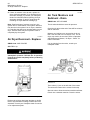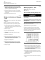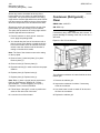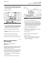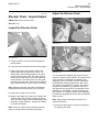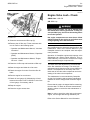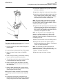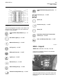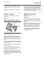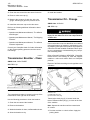
1
MAINTENANCE INTERVALS
Operation and Maintenance
Manual Excerpt
© 2010 Caterpillar
All Rights Reserved
®
®
SEBU7857-04
August 2010
Operation and
Maintenance
Manual
623G Wheel Tractor-Scraper
DBC1-Up (Machine)
DBY1-Up (Scraper)
SAFETY.CAT.COM
SEBU7857-04
93
Maintenance Section
Maintenance Interval Schedule
i04024573
Maintenance Interval Schedule
SMCS Code: 1000; 7000; 7500; 7519
Ensure that all safety information, warnings and
instructions are read and understood before any
operation or any maintenance procedures are
performed.
The user is responsible for the performance of
maintenance, including all adjustments, the use of
proper lubricants, fluids, filters, and the replacement
of components due to normal wear and aging. Failure
to adhere to proper maintenance intervals and
procedures may result in diminished performance of
the product and/or accelerated wear of components.
Use mileage, fuel consumption, service hours, or
calendar time, WHICH EVER OCCURS FIRST,
in order to determine the maintenance intervals.
Products that operate in severe operating conditions
may require more frequent maintenance.
Note: Before each consecutive interval is performed,
all maintenance from the previous interval must be
performed.
When Required
Battery - Recycle .................................................. 97
Battery or Battery Cable - Inspect/Replace .......... 97
Circuit Breakers - Reset ...................................... 102
Clearance between Elevator Flight and Cutting Edge
- Check/Adjust ................................................... 103
Cutting Edges and End Bits - Inspect/Replace .... 111
Draft Arm Wear Plates - Check/Adjust ................ 114
Ejector Carrier Rollers - Check/Adjust ................. 115
Ejector Guide Rollers - Check/Adjust .................. 116
Ejector Support Rollers - Check/Adjust ............... 117
Elevator Chain - Inspect/Adjust ........................... 119
Engine Air Filter Primary Element - Clean/
Replace ............................................................. 123
Engine Air Filter Secondary Element - Replace .. 125
Engine Air Filter Service Indicator Inspect/Replace ................................................ 126
Ether Starting Aid Cylinder - Replace ................. 132
Fuel System - Prime ........................................... 133
Fuses - Replace .................................................. 138
Oil Filter - Inspect ................................................ 147
Secondary Steering - Test .................................. 149
Steering Pump Outlet Screen - Clean ................ 150
Window Washer Reservoir - Fill .......................... 157
Window Wiper - Inspect/Replace ........................ 157
Windows - Clean ................................................. 157
Every 10 Service Hours or Daily
Air Tank Moisture and Sediment - Drain ............... 96
Backup Alarm - Test .............................................. 97
Brakes, Indicators and Gauges - Test ................. 100
Cooling System Coolant Level - Check ..............
Elevator Chain Idler - Lubricate ..........................
Engine Air Filter Service Indicator - Inspect ........
Engine Air Precleaner - Clean ............................
Engine Oil Level - Check ....................................
Floor Rollers - Lubricate .....................................
Fuel System Water Separator - Drain .................
Fuel Tank Water and Sediment - Drain ...............
Hydraulic Oil Cooler - Clean ...............................
Hydraulic System Oil Level - Check ...................
Radiator Core - Clean .........................................
Seat Belt - Inspect ..............................................
107
121
126
127
128
133
137
138
140
145
147
149
Initial 50 Service Hours
Transmission Oil Filter and Magnetic Screen Replace/Clean .................................................. 153
Every 50 Service Hours or Weekly
Cab Air Filter - Clean/Replace ............................
Elevator Chain Adjustment Cylinder - Lubricate ..
Hitch - Lubricate ..................................................
Tire Inflation - Check ...........................................
101
120
140
151
Initial 250 Service Hours (or at first oil
change)
Electronic Unit Injector - Inspect/Adjust ............... 118
Engine Valve Lash - Check ................................. 131
Evaporator Coil and Heater Coil - Clean ............ 132
Every 250 Service Hours
Cooling System Coolant Sample (Level 1) Obtain ............................................................... 107
Every 250 Service Hours or Monthly
Air Dryer - Check .................................................. 95
Belts - Inspect/Replace ......................................... 98
Brake Air System Pressure - Test ......................... 98
Braking System - Test ......................................... 100
Differential and Final Drive Oil Level - Check ...... 114
Elevator Chain Roller - Check/Lubricate ............. 121
Elevator Speed Reducer - Check/Lubricate ....... 122
Engine Oil Sample - Obtain ................................ 129
Hydraulic System Oil Sample - Obtain ............... 145
Transmission Oil Level - Check .......................... 154
Transmission Oil Sample - Obtain ...................... 155
Wheel Bearing Oil Level - Check ........................ 156
Initial 500 Hours (for New Systems, Refilled
Systems, and Converted Systems)
Cooling System Coolant Sample (Level 2) Obtain ............................................................... 108
Every 500 Service Hours or 3 Months
Accumulator (Cushion Hitch) - Check ................... 95
Brake Camshaft Bearing - Lubricate ..................... 99
Differential and Final Drive Oil Sample - Obtain .. 114
94
Maintenance Section
Maintenance Interval Schedule
Engine Oil (High Speed) and Oil Filter - Change .. 127
Engine Oil and Filter - Change ........................... 129
Fuel System Primary Filter (Water Separator)
Element - Replace ............................................ 134
Fuel System Secondary Filter - Replace ............ 136
Fuel Tank Cap and Strainer - Clean ................... 137
Hydraulic System Oil Filter (Gear Pump and Case
Drain) - Replace ................................................ 142
Hydraulic System Oil Filter (Pilot) - Replace ....... 143
Hydraulic System Oil Filter - Replace ................. 144
Hydraulic Tank Breaker Relief Valve - Clean ...... 146
Transmission Oil Filter and Magnetic Screen Replace/Clean .................................................. 153
Every 1000 Service Hours or 6 Months
Air Dryer Desiccant - Replace .............................. 96
Battery - Clean/Check ........................................... 97
Brake Air System Warning Horn - Test ................. 99
Differential and Final Drive Breather - Clean ....... 112
Rollover Protective Structure (ROPS) - Inspect .. 148
Suction Screen (Transmission Scavenge) Clean ................................................................. 150
Transmission Breather - Clean ........................... 152
Transmission Oil - Change ................................. 152
Wheel Coolant Level - Check ............................. 156
Every 2000 Service Hours
Elevator Speed Reducer Oil - Change ............... 122
Every 2000 Service Hours or 1 Year
Brake Shoes and Drums - Inspect/Replace .......... 99
Condenser (Refrigerant) - Clean ........................ 104
Differential Thrust Pin Clearance - Check ........... 112
Differential and Final Drive Oil - Change ............. 112
Ejector Carrier Rollers - Inspect/Pack/Replace ... 116
Ejector Guide Rollers - Inspect/Pack/Replace ..... 117
Ejector Support Rollers - Inspect/Pack/Replace .. 118
Electronic Unit Injector - Inspect/Adjust ............... 118
Elevator Drive Tube Roller Bearing - Lubricate .. 122
Engine Valve Lash - Check ................................. 131
Evaporator Coil and Heater Coil - Clean ............ 132
Hitch - Inspect ..................................................... 139
Hydraulic System Oil - Change ........................... 141
Wheel Bearing Oil - Change ............................... 155
Every Year
Cooling System Coolant Sample (Level 2) Obtain ............................................................... 108
Engine Air Filter Service Indicator Inspect/Replace ................................................ 126
Refrigerant Dryer - Replace ................................ 148
Every 3000 Service Hours or 2 Years
Cooling System Pressure Cap - Clean/Replace .. 109
Cooling System Water Temperature Regulator Replace ............................................................. 109
Crankshaft Vibration Damper - Inspect ................ 110
SEBU7857-04
Every 3 Years After Date of Installation or
Every 5 Years After Date of Manufacture
Seat Belt - Replace ............................................. 149
Every 6000 Service Hours or 3 Years
Cooling System Coolant Extender (ELC) - Add .. 106
Every 12 000 Service Hours or 6 Years
Cooling System Coolant (ELC) - Change ........... 105
SEBU7857-04
95
Maintenance Section
Accumulator (Cushion Hitch) - Check
i02228281
i01778508
Accumulator (Cushion Hitch) Check
Air Dryer - Check
SMCS Code: 5077-535
S/N: DBC1-Up
SMCS Code: 4285-535
S/N: DBC1-Up
Illustration 86
g01124228
The cushion-hitch accumulator is located on the right
side of the machine near the center hitch.
Check the precharge pressure in the cushion-hitch
accumulator. Add nitrogen, if necessary. Refer to
Specifications, Systems Operation, Testing and
Adjusting, “Accumulator (Cushion-Hitch) - Test and
Charge”. You may need to consult your Caterpillar
dealer for the checking procedure.
Illustration 87
g00910985
1. Open drain valves (1) for the air tanks on the
tractor. The air tanks should have air pressure.
There are three valves on the tractor.
2. Check for moisture in the air tank. Moisture will
spray from drain valves (1) if moisture is present.
Close drain valves (1).
3. Open access door (2).
Illustration 88
g00909446
96
Maintenance Section
Air Dryer Desiccant - Replace
SEBU7857-04
4. If there is moisture in the air tank, replace air
dryer desiccant cartridge (3) or rebuild air dryer
desiccant cartridge (3). Consult your Caterpillar
dealer for information about replacing air dryer
desiccant cartridge (3) and for instructions for
rebuilding air dryer desiccant cartridge (3).
Note: Small amounts of moisture may be in the
system due to condensation in the system. Moisture
may also be in the system if an air dryer is installed
on a machine that has been operating without an air
dryer. Several weeks may be required in order to
completely dry the system.
i01778591
Air Dryer Desiccant - Replace
i01778832
Air Tank Moisture and
Sediment - Drain
SMCS Code: 4272-543-M&S
The air tanks should have some air pressure.
Check the air tanks at the end of the shift for moisture
and for sediment.
Moisture and sediment can accumulate in the air
tank. This can lead to a low reserve of air. The air
dryer may need to be serviced. Refer to Operation
and Maintenance Manual, “Air Dryer - Check” for
further information.
If oil is draining from the tanks, consult your
Caterpillar dealer.
SMCS Code: 4285-510-DSS
S/N: DBC1-Up
Air lines to and from the air dryer must be at
atmospheric pressure. Release the air pressure
from the air system completely before performing
maintenance.
Illustration 90
g00909442
Three valves (1) are on the left side of the tractor.
The valves are located in the recess for the step.
Open the valves. Allow the moisture and the sediment
to drain into a suitable container. Close the valves.
Illustration 89
g00909536
Replace the air dryer desiccant cartridge or rebuild
the air dryer desiccant cartridge if water cannot be
absorbed. Consult your Caterpillar dealer for service
or for replacement parts.
SEBU7857-04
97
Maintenance Section
Backup Alarm - Test
2. Turn the battery disconnect switch to the OFF
position. Remove the key.
3. At the battery disconnect switch, disconnect the
negative battery cable that is connected to the
frame.
Note: Do not allow the disconnected battery cable to
contact the disconnect switch.
4. Check the battery terminals for corrosion. If
corrosion is present, clean the battery terminals
with a wire brush.
Illustration 91
g00909637
5. Coat the battery terminals with petroleum jelly, if
necessary.
The air tank for the scraper is on the right rear side
of the scraper.
6. Connect the negative battery cable at the battery
disconnect switch.
Open drain valve (2). Allow the moisture and the
sediment to drain into a suitable container. Close
valve (2).
7. Install the key for the battery disconnect switch.
Turn the key to the ON position.
i03639910
Backup Alarm - Test
i00993589
Battery - Recycle
SMCS Code: 1401-561
SMCS Code: 7406-081
The backup alarm is on the rear of the machine.
1. Turn the engine start switch to the ON position in
order to perform the test.
Always recycle a battery. Never discard a battery.
Always return used batteries to one of the following
locations:
• A battery supplier
2. Apply the service brakes.
3. Move the transmission control lever to the
REVERSE position. The backup alarm should
start to sound immediately.
The backup alarm should sound immediately. The
alarm alerts the personnel behind the machine
that the machine is backing up. The backup alarm
should continue to sound until the transmission
control lever is moved to the NEUTRAL position
or to the FORWARD position.
i01851167
• An authorized battery collection facility
• Recycling facility
i01851175
Battery or Battery Cable Inspect/Replace
SMCS Code: 1401-040; 1401-510; 1402-040;
1402-510
Battery - Clean/Check
1. Turn the engine start switch to the OFF position.
Turn all switches to the OFF position.
SMCS Code: 1401-070; 1401-535; 1402-070;
1402-535
2. Turn the battery disconnect switch to the OFF
position. Remove the key.
S/N: DBC1-Up
3. At the battery disconnect switch, disconnect the
negative battery cable that is connected to the
frame.
1. Turn the engine start switch to the OFF position.
Turn all switches to the OFF position.
Note: Do not allow the disconnected battery cable to
contact the disconnect switch.
98
Maintenance Section
Belts - Inspect/Replace
SEBU7857-04
4. Disconnect the negative battery cable from the
terminals of the battery.
5. Perform the necessary repairs. Replace the cable
or the battery, as needed.
6. Connect the negative battery cable to the
terminals of the battery.
• excessive damage
• missing pieces
• frayed areas
4. Close the engine access cover.
7. Connect the negative battery cable at the battery
disconnect switch.
8. Install the key for the battery disconnect switch.
Turn the key to the ON position.
Replace
If the belts need replacement, refer to the Service
Manual or contact your local Caterpillar dealer.
i02443636
Belts - Inspect/Replace
Brake Air System Pressure Test
SMCS Code: 1397-040; 1397-510
SMCS Code: 4250-081-PX
i03639915
S/N: DBC1-Up
Inspect
Illustration 92
g01117288
(1) Fan drive belt
(2) Air conditioning compressor and alternator drive belt
Illustration 93
1. Park the machine on level ground. Move the
transmission control to the NEUTRAL position and
engage the parking brake. Shut off the engine.
1. Start the engine and look at air pressure gauge
(2). Allow the brake system air pressure to reach
850 ± 50 kPa (125 ± 10 psi).
2. Open the engine access cover that is on the right
side of the tractor.
2. Apply the service brake by holding down service
brake pedal (1).
3. Inspect the condition of the fan drive belt (1).
Inspect the condition of the air conditioning
compressor and alternator drive belt (2). Inspect
the belts for the following conditions:
3. Stop the engine.
• excessive cracking
• excessive wear
• excessive stretching
g01220965
4. The reading on the air pressure gauge should not
drop by more than 35 kPa (5 psi) after the engine
is stopped for 10 minutes. Repair the brakes, if
necessary.
SEBU7857-04
99
Maintenance Section
Brake Air System Warning Horn - Test
i01401548
Brake Air System Warning
Horn - Test
SMCS Code: 7402-081; 7408-081
The warning horn for the air brake system should
sound when the air pressure gauge shows a reading
below 517 ± 35 kPa (75 ± 5 psi).
1. The parking brake should be in the ENGAGED
position.
2. The transmission control should be in the
NEUTRAL position.
g01152437
Illustration 95
Scraper wheel
3. Start the engine.
4. Watch the air pressure gauge. The air pressure
must be above 517 ± 35 kPa (75 ± 5 psi).
5. Purge air from the air tanks by doing the following
procedure:
• Engage and disengage the service brake until
the air pressure drops below 517 ± 35 kPa
(75 ± 5 psi).
The warning horn should sound and the action
lamp should flash. Make repairs if the warning
horn is not sounding or the action lamp is not
flashing.
i02556186
Brake Camshaft Bearing Lubricate
The grease fittings for the brake camshaft bearings
can be reached from the back side of each wheel.
1. Remove the covers that are on the fittings.
2. Wipe the fittings before you apply lubricant
through the fittings.
3. Apply the appropriate lubricant through the fittings
for the tractor wheels and for the scraper wheels
in order to lubricate the brake camshaft bearings.
4. Replace the covers for the fittings.
i01792845
Brake Shoes and Drums Inspect/Replace
SMCS Code: 4252-040; 4252-510; 4253-040;
4253-510
SMCS Code: 4251-086-BD
Illustration 96
Illustration 94
Tractor wheel
g00919030
g00920131
Front Wheel
Note: Check the brakes on all four wheels. Rear
wheels are similar to the front wheels.
1. Remove the wheel brake dust covers.
100
Maintenance Section
Brakes, Indicators and Gauges - Test
SEBU7857-04
2. Check the brake shoes for wear or for damage.
Measure the thickness of the brake linings. If the
thickness of the brake linings is less than 7.2 mm
(0.28 inch), replace the brake linings.
3. Check the brake drum for wear or for damage.
Repair the brake drum or replace the brake drum,
if necessary.
4. Install the wheel brake dust cover.
i02444593
Brakes, Indicators and Gauges
- Test
i02243155
Braking System - Test
SMCS Code: 4251-081; 4267-081
S/N: DBC1-Up
Service Brake Holding Ability Test
Personal injury can result if the machine moves
while testing.
SMCS Code: 4251-081; 4267-081; 7000; 7450-081;
7490-081
If the machine begins to move during test, reduce
the engine speed immediately and engage the
parking brake.
Before you operate the machine, perform the
following checks and make any necessary repairs:
Make sure that the area around the machine is clear
of personnel and of obstacles.
1. Look for broken lenses on the gauges, broken
indicator lights, broken switches, and other broken
components in the cab.
Test the brakes on a dry, level surface.
2. Start the engine.
This test determines whether the service brake is
functional. This test is not intended to measure the
maximum brake holding effort.
3. Look for inoperative gauges.
Fasten the seat belt before you test the brakes.
4. Turn on all machine lights. Check for proper
operation.
5. Sound the forward horn.
6. Move the machine forward and test the service
brakes. If the service brakes malfunction, consult
your Caterpillar dealer for proper repair.
7. Engage the parking brake.
8. Move the machine forward in order to test the
parking brake. If the parking brake malfunctions,
consult your Caterpillar dealer for proper repair.
9. Stop the engine.
Illustration 97
g01132855
1. Start the tractor engine and the scraper engine.
Scroll to Numeric Readout Mode on display area
(1). Look at the air pressure on display area (1).
Allow the brake system air pressure to reach the
cut out pressure for the throttle.
2. Disengage the scraper transmission by moving
the scraper transmission neutral/run switch to the
DISENGAGE position.
3. Raise the bowl.
4. Apply the service brake and release the parking
brake.
SEBU7857-04
5. While the engine is at an idle and the service
brake is applied, move the transmission control to
the SECOND SPEED position.
6. Gradually increase the engine rpm. The service
brake should prevent machine movement when
the engine is running at 1200 rpm or less.
If the machine moves with the engine rpm less
than 1200 rpm, consult your Caterpillar dealer for
an inspection of the machine.
7. Reduce the engine speed to low idle and move
the transmission control to the NEUTRAL position.
Engage the parking brake. Lower the bowl to the
ground and stop the engine.
NOTICE
If the machine moved while testing the brakes, contact
your Caterpillar Dealer. Have the dealer inspect and, if
necessary, repair the service brakes before returning
the machine to operation.
Note: If the friction material for the brakes needs to
be replaced, the new friction material may require
conditioning for maximum performance. Consult
your Caterpillar dealer or see Special Instruction,
SEHS9187 for the procedure for conditioning.
Parking And Secondary Brake
Holding Ability Test
Make sure that no people or obstacles are in the area
around the machine.
Test the brakes on a dry, level surface.
Fasten the seat belt before you test the brakes.
This test determines whether the parking brake is
functional. This test is not intended to measure the
maximum brake holding effort.
1. Start the tractor engine and the scraper engine.
Scroll to Numeric Readout Mode on display area
(1). Look at the air pressure on display area (1).
Allow the brake system air pressure to reach the
cut out pressure for the throttle.
2. Disengage the scraper transmission by moving
the scraper transmission neutral/run switch to the
DISENGAGE position.
3. Raise the bowl.
4. Apply the parking brake.
5. While the engine is at an idle and the parking
brake is applied, move the transmission control to
the SECOND SPEED position.
101
Maintenance Section
Cab Air Filter - Clean/Replace
If the machine begins to move, reduce the engine
speed immediately and apply the service brake
pedal.
6. Gradually increase the engine rpm. The parking
brake should prevent machine movement when
the engine is running at 1000 rpm or less.
If the machine moves with the engine rpm less
than 1000 rpm, consult your Caterpillar dealer for
an inspection of the machine.
7. Reduce the engine speed and move the
transmission control to the NEUTRAL position.
Lower the bowl to the ground and stop the engine.
NOTICE
If the machine moved while testing the brakes, contact
your Caterpillar Dealer. Have the dealer inspect and, if
necessary, repair the service brakes before returning
the machine to operation.
Note: If the friction material for the brakes needs to
be replaced, the new friction material may require
conditioning for maximum performance. Consult
your Caterpillar dealer or see Special Instruction,
SEHS9187 for the procedure for conditioning.
i02301254
Cab Air Filter - Clean/Replace
SMCS Code: 7342-070; 7342-510
S/N: DBC1-Up
Cleaning the Filters
Outside Filters
Note: Clean the air filters more often during dusty
conditions.
102
Maintenance Section
Circuit Breakers - Reset
SEBU7857-04
Inside Filter
Illustration 100
g01152478
1. Remove latches (4) which hold the filter element
in place. Remove access cover (5).
Illustration 98
g01166341
1. Open access door (1). Install rod (2) in order to
secure the access door.
Note: Use the appropriate equipment in order to open
the access door and install the rod from the ground.
2. Remove the filter element. Clean the filter element
with pressure air or wash the filter element in warm
water. Use a nonsudsing household detergent.
Rinse the filter element in clean water and air dry
the filter element thoroughly.
3. After you clean the filter element, inspect the filter
element. Do not use a filter element with damaged
pleats or a damaged seal. If the filter element is
damaged, replace the filter element.
4. Install the filter element. Reinstall access cover
(5). Replace latches (4).
i02500897
Circuit Breakers - Reset
SMCS Code: 1420-529
S/N: DBC1-Up
Illustration 99
g01166347
Circuit Breakers
2. Remove latches (3) which hold the filter element
in place.
3. Remove the filter element. Clean the filter element
with pressure air or wash the filter element in warm
water. Use a nonsudsing household detergent.
Rinse the filter element in clean water and air dry
the filter element thoroughly.
4. After you clean the filter element, inspect the filter
element. Do not use a filter element with damaged
pleats or a damaged seal. If the filter element is
damaged, replace the filter element.
5. Install the filter element. Replace latches (3).
Reinstall the access cover.
Illustration 101
g01229770
SEBU7857-04
103
Maintenance Section
Clearance between Elevator Flight and Cutting Edge - Check/Adjust
The circuit breakers for the tractor are located at the
left side of the operator's seat.
Circuit Breaker/Reset – Push in the
button in order to reset the circuit breaker. If
the electrical system is working properly, the
button will remain depressed. If the button does not
remain depressed, check the appropriate electrical
circuit. Repair the electrical circuit, if necessary.
Blower Motor (1) – 20 AMP
24 V Electrical Socket (7)
Advanced Diesel Engine Management
(8) – 15 AMP
i01970010
Clearance between Elevator
Flight and Cutting Edge Check/Adjust
Keyswitch (2) – 10 AMP
SMCS Code: 6232-025; 6232-535
Headlamp (3) (If Equipped) – 15 AMP
S/N: DBY1-Up
Stop/Tail/Turn Lamp (4) (If Equipped) –
10 AMP
Circuit Breaker Panel
Illustration 103
Illustration 102
g01221006
The circuit breaker panel is located below the cab
on the left side of the tractor. Access to the circuit
breakers is through an opening on the left side of the
front frame.
Alternator (5) – 80 AMP
Main Power (6) – 80 AMP
g01022737
The clearance between the elevator flights and the
top of the cutting edge may be adjusted. The distance
between the top of the cutting edge and the elevator
flights is set at the factory at approximately 61 mm
(2.4 inches). Two shims (5) are located on top of the
welded bracket when the machine is shipped from
the factory. The welded brackets are located on each
side of the bowl. The shims must be equally placed
on each of the brackets. Special plates (3) and (4)
are located above the removable shims (5). Plates
(3) and (4) must remain in the top position. The top
two plates prevent damage to the attaching bolts
(2). Four shims (5) are located on the bottom of the
welded bracket when the machine is shipped from
the factory.
104
Maintenance Section
Condenser (Refrigerant) - Clean
Shims may need to be added to the top of the
bracket when you are working in material which is
compacted. The space that is between the cutting
edge and the elevator flight will become wider. Shims
may also need to be added to the top of the bracket
when the components of the elevator become worn.
Shims may need to be removed from the top of the
bracket when you are working in loose material.
The space that is between the cutting edge and the
elevator flight will become narrower.
1. Park the machine on level ground. Lower the
bowl. Apply the parking brake.
2. You should raise the front of the elevator with a
jack or a hoist. Place blocks or stands under the
front of the elevator once the elevator has been
raised. Lower the elevator until the elevator is
resting on the blocks or stands.
SEBU7857-04
i02207380
Condenser (Refrigerant) Clean
SMCS Code: 1805-070
S/N: DBC1-Up
NOTICE
If excessively dirty, clean condenser with a brush. To
prevent damage or bending of the fins, do not use a
stiff brush.
Repair the fins if found defective.
Note: The front of the elevator must not be resting
on the top plate.
3. Remove bolts (1) that hold plate (3) in place.
Remove plate (3).
4. Remove bolts (2). Remove plate (4).
5. Reposition shims (5) in order to achieve the proper
distance.
6. Replace plate (4). Replace bolts (2).
7. Replace plate (3). Replace bolts (1).
Illustration 104
g01114468
The refrigerant condenser is located behind the front
radiator grill.
Note: Bolts (1) have a special torque requirement.
Refer to Specifications, SENR3130, “Torque
Specifications”, “Ground Engaging Tool (G.E.T.)
Fasteners” for the correct information.
1. Remove the radiator grill.
8. Follow Steps 3 through 5 in order to position the
shims on the other side of the bowl.
3. Use clean water in order to wash off all dust and
dirt from the condenser.
9. Lower the front of the elevator.
4. Replace the radiator grill.
2. Inspect the condenser for debris. If necessary,
clean the condenser.
SEBU7857-04
105
Maintenance Section
Cooling System Coolant (ELC) - Change
i02500932
S/N: DBC1-Up
NOTICE
Care must be taken to ensure that fluids are contained
during performance of inspection, maintenance, testing, adjusting and repair of the product. Be prepared to
collect the fluid with suitable containers before opening any compartment or disassembling any component containing fluids.
Personal injury can result from hot coolant, steam
and alkali.
Refer to Special Publication, NENG2500, “Caterpillar
Dealer Service Tool Catalog” for tools and supplies
suitable to collect and contain fluids on Caterpillar
products.
Cooling System Coolant (ELC)
- Change
SMCS Code: 1350-044-NL
At operating temperature, engine coolant is hot
and under pressure. The radiator and all lines
to heaters or the engine contain hot coolant or
steam. Any contact can cause severe burns.
Dispose of all fluids according to local regulations and
mandates.
Remove filler cap slowly to relieve pressure only
when engine is stopped and radiator cap is cool
enough to touch with your bare hand.
If the coolant in the machine is changed to Extended
Life Coolant (ELC) from another type of coolant,
refer to Special Publication, SEBU6250, “Caterpillar
Machine Fluids Recommendations”, “Cat Extended
Life Coolant (ELC)”.
Do not attempt to tighten hose connections when
the coolant is hot, the hose can come off causing
burns.
If the coolant is dirty or if you observe any foaming
in the cooling system, drain the coolant before the
recommended interval.
Cooling System Conditioner contains alkali. Avoid
contact with skin and eyes.
1. Park the machine on a level surface and engage
the parking brake. Stop the engine. Allow the
engine to cool.
NOTICE
Do not change the coolant until you read and understand the cooling system information in Special Publication, SEBU6250, “Caterpillar Machine Fluids Recommendations”.
2. Loosen the cooling system pressure cap slowly in
order to release the pressure. Remove the cooling
system pressure cap.
Failure to do so could result in damage to the cooling
system components.
NOTICE
Mixing ELC with other products reduces the effectiveness of the coolant and shortens coolant life. Use only
Caterpillar products or commercial products that have
passed the Caterpillar EC-1 specifications for premixed or concentrate coolants. Use only Caterpillar
Extender with Caterpillar ELC. Failure to follow these
recommendations could result in the damage to cooling systems components.
If ELC cooling system contamination occurs see the
topic Extended Life Coolant (ELC) in the Special Publication, SEBU6250, “Caterpillar Machine Fluids Recommendations”.
Illustration 105
g01115071
3. The coolant drain valve is located behind guard
(2). Remove access cover (1) for the coolant drain
valve.
4. Open the coolant drain valve. Drain the coolant
into a suitable container.
5. Flush the cooling system with clean water until the
draining water is transparent.
106
Maintenance Section
Cooling System Coolant Extender (ELC) - Add
6. Close the coolant drain valve. Install the access
cover.
7. Add ELC. Refer to the following topics:
• Special Publication, SEBU6250, “Caterpillar
Machine Fluids Recommendations”, “Cooling
System Specifications”
SEBU7857-04
When Caterpillar Extended Life Coolant (ELC)
is used, an extender must be added to the
cooling system. See Operation and Maintenance
Manual, “Maintenance Interval Schedule” for the
proper service interval. The amount of extender is
determined by the cooling system capacity.
Table 11
Amount of Caterpillar Extender (ELC)
• Operation and Maintenance Manual, “Capacities
Cooling System Capacity
Recommended Amount
of Caterpillar Extender
22 to 30 L (6 to 8 US gal)
0.57 L (20 oz)
31 to 38 L (8 to 10 US gal)
0.71 L (24 oz)
39 to 49 L (10 to 13 US gal)
0.95 L (32 oz)
50 to 64 L (13 to 17 US gal)
1.18 L (40 oz)
65 to 83 L (17 to 22 US gal)
1.60 L (54 oz)
84 to 114 L (22 to 30 US gal)
2.15 L (72 oz)
115 to 163 L (30 to 43 US gal)
3.00 L (100 oz)
164 to 242 L (43 to 64 US gal)
4.40 L (148 oz)
(Refill)”
8. Start the engine. Operate the engine without
the cooling system pressure cap until the water
temperature regulator opens and the coolant level
stabilizes.
9. Check the coolant level. The radiator is full when
the sight glass is completely covered. Also, the
radiator is full when the coolant level reaches the
top of the angled cut on the filler tube. Refer to
Operation and Maintenance Manual, “Cooling
System Coolant Level - Check”.
10. Inspect the gasket of the cooling system pressure
cap. If the gasket is damaged, replace the gasket.
11. Install the cooling system pressure cap.
Note: For cooling systems with larger capacities,
use the formula in Table 12 in order to determine the
correct amount of extender.
12. Stop the engine.
Table 12
Calculation of ELC Extender
i02336986
Cooling System Coolant
Extender (ELC) - Add
SMCS Code: 1352-544-NL
S/N: DBC1-Up
Personal injury can result from hot coolant, steam
and alkali.
At operating temperature, engine coolant is hot
and under pressure. The radiator and all lines
to heaters or the engine contain hot coolant or
steam. Any contact can cause severe burns.
Remove filler cap slowly to relieve pressure only
when engine is stopped and radiator cap is cool
enough to touch with your bare hand.
Do not attempt to tighten hose connections when
the coolant is hot, the hose can come off causing
burns.
Cooling System Conditioner contains alkali. Avoid
contact with skin and eyes.
V(1) × 0.02 = X(2)
(1)
(2)
V is the total volume of the cooling system.
X is the amount of ELC Extender that is required.
For additional information about adding an extender,
see Special Publication, SEBU6250, “Caterpillar
Machine Fluids Recommendations”, “Extended Life
Coolant (ELC)” or consult your Caterpillar dealer.
SEBU7857-04
107
Maintenance Section
Cooling System Coolant Level - Check
i02500944
Cooling System Coolant Level
- Check
Note: The filler tube has an angled cut inside of
the coolant tank that can also be used to check the
coolant level. Add coolant when the coolant level
reaches the bottom of the angled cut on the filler tube.
4. If additional coolant is needed, remove the
pressure cap slowly in order to relieve the
pressure.
SMCS Code: 1350-535-FLV
S/N: DBC1-Up
5. Add more coolant.
Personal injury can result from hot coolant, steam
and alkali.
At operating temperature, engine coolant is hot
and under pressure. The radiator and all lines
to heaters or the engine contain hot coolant or
steam. Any contact can cause severe burns.
Remove filler cap slowly to relieve pressure only
when engine is stopped and radiator cap is cool
enough to touch with your bare hand.
Do not attempt to tighten hose connections when
the coolant is hot, the hose can come off causing
burns.
Cooling System Conditioner contains alkali. Avoid
contact with skin and eyes.
The coolant level sight gauge is located on top of the
radiator on the right side of the coolant tank.
Note: The radiator is full when the sight gauge is
completely covered. Also, the radiator is full when
the coolant level reaches the top of the angled cut on
the filler tube.
i02500922
Cooling System Coolant
Sample (Level 1) - Obtain
SMCS Code: 1350-008
S/N: DBC1-Up
Note: Obtaining a Coolant Sample (Level 1) is
optional if the cooling system is filled with Cat
ELC (Extended Life Coolant). Cooling systems that
are filled with Cat ELC should have a Coolant Sample
(Level 2) that is obtained at the recommended interval
that is stated in the Maintenance Interval Schedule.
Note: Obtain a Coolant Sample (Level 1) if the
cooling system is filled with any other coolant
instead of Cat ELC. This includes the following
types of coolants:
• Commercial long life coolants that meet the
Caterpillar Engine Coolant Specification -1
(Caterpillar EC-1)
• Cat Diesel Engine Antifreeze/Coolant (DEAC)
• Commercial heavy-duty antifreeze/coolant
Illustration 106
g01114916
1. Park the machine on level ground. Engage the
parking brake.
2. Stop the engine.
3. Check the coolant level in the sight gauge. If the
coolant level is at the bottom of the sight gauge,
more coolant is needed.
NOTICE
Care must be taken to ensure that fluids are contained
during performance of inspection, maintenance, testing, adjusting and repair of the product. Be prepared to
collect the fluid with suitable containers before opening any compartment or disassembling any component containing fluids.
Refer to Special Publication, NENG2500, “Caterpillar
Dealer Service Tool Catalog” for tools and supplies
suitable to collect and contain fluids on Caterpillar
products.
Dispose of all fluids according to local regulations and
mandates.
108
Maintenance Section
Cooling System Coolant Sample (Level 2) - Obtain
Note: Level 1 results may indicate a need for
Level 2 Analysis.
SEBU7857-04
i02444355
Cooling System Coolant
Sample (Level 2) - Obtain
SMCS Code: 1350-008
S/N: DBC1-Up
NOTICE
Care must be taken to ensure that fluids are contained
during performance of inspection, maintenance, testing, adjusting and repair of the product. Be prepared to
collect the fluid with suitable containers before opening any compartment or disassembling any component containing fluids.
Illustration 107
g01116606
Obtain the sample of the coolant as close as possible
to the recommended sampling interval. In order
to receive the full effect of S·O·S coolant analysis,
you must establish a consistent trend of data.
In order to establish a pertinent history of data,
perform consistent samplings that are evenly spaced.
Supplies for collecting samples can be obtained from
your Caterpillar dealer.
Use the following guidelines for proper sampling of
the coolant:
Refer to Special Publication, NENG2500, “Caterpillar
Dealer Service Tool Catalog” for tools and supplies
suitable to collect and contain fluids on Caterpillar
products.
Dispose of all fluids according to local regulations and
mandates.
Obtain the sample of the coolant as close as possible
to the recommended sampling interval. Supplies
for collecting samples can be obtained from your
Caterpillar dealer.
• Complete the information on the label for the
Refer to Operation and Maintenance Manual,
“Cooling System Coolant Sample (Level 1) - Obtain”
for the guidelines for proper sampling of the coolant.
• Keep the unused sampling bottles stored in plastic
Submit the sample for Level 2 analysis.
• Obtain coolant samples directly from the coolant
sample port. You should not obtain the samples
from any other location.
Reference: For additional information about coolant
analysis, refer to Special Publication, SEBU6250,
“Caterpillar Machine Fluids Recommendations” or
consult your Caterpillar dealer.
sampling bottle before you begin to take the
samples.
bags.
• Keep the lids on empty sampling bottles until you
are ready to collect the sample.
• Place the sample in the mailing tube immediately
after obtaining the sample in order to avoid
contamination.
• Never collect samples from expansion bottles.
• Never collect samples from the drain for a system.
Submit the sample for Level 1 analysis.
For additional information about coolant analysis,
refer to Special Publication, SEBU6250, “Caterpillar
Machine Fluids Recommendations” or consult your
Caterpillar dealer.
SEBU7857-04
109
Maintenance Section
Cooling System Pressure Cap - Clean/Replace
i02500949
Cooling System Pressure Cap
- Clean/Replace
SMCS Code: 1382-070; 1382-510
S/N: DBC1-Up
5. Install the pressure cap.
i02558927
Cooling System Water
Temperature Regulator Replace
SMCS Code: 1355-510
Personal injury can result from hot coolant, steam
and alkali.
S/N: DBC1-Up
At operating temperature, engine coolant is hot
and under pressure. The radiator and all lines
to heaters or the engine contain hot coolant or
steam. Any contact can cause severe burns.
Personal injury can result from hot coolant, steam
and alkali.
Remove filler cap slowly to relieve pressure only
when engine is stopped and radiator cap is cool
enough to touch with your bare hand.
At operating temperature, engine coolant is hot
and under pressure. The radiator and all lines
to heaters or the engine contain hot coolant or
steam. Any contact can cause severe burns.
Do not attempt to tighten hose connections when
the coolant is hot, the hose can come off causing
burns.
Remove filler cap slowly to relieve pressure only
when engine is stopped and radiator cap is cool
enough to touch with your bare hand.
Cooling System Conditioner contains alkali. Avoid
contact with skin and eyes.
Do not attempt to tighten hose connections when
the coolant is hot, the hose can come off causing
burns.
The cooling system pressure cap is located on the
top of the radiator underneath the hood cover.
Cooling System Conditioner contains alkali. Avoid
contact with skin and eyes.
Replace the water temperature regulator for the
cooling system on a regular basis in order to reduce
the chance of unscheduled downtime. Replace the
water temperature regulator for the cooling system
on a regular basis in order to reduce the chance of
problems with the cooling system.
Illustration 108
g01114644
1. Remove the cooling system pressure cap slowly
in order to relieve the pressure.
2. Inspect the cap for damage, for foreign material,
and for deposits.
The water temperature regulator should be replaced
after the cooling system has been cleaned. Replace
the water temperature regulator while the cooling
system is completely drained or while the cooling
system coolant is drained to a level that is below the
housing assembly of the water temperature regulator.
NOTICE
Failure to replace the engine's water temperature regulator on a regularly scheduled basis could cause severe engine damage.
3. Clean the cap with a clean cloth or replace the
cap, if necessary.
1. Drain the cooling system coolant to a level that
is below the housing assembly of the water
temperature regulator.
4. Inspect the condition of the gasket in the cap.
Replace the gasket, if necessary.
2. Loosen the hose clamp and remove the hose from
the water temperature regulator housing.
110
Maintenance Section
Crankshaft Vibration Damper - Inspect
3. Remove the turbocharger water line from the
cover assembly.
4. Clean the area around the water temperature
regulator housing.
5. Remove the bolts from the water temperature
regulator housing and remove the water
temperature regulator housing.
SEBU7857-04
i02469814
Crankshaft Vibration Damper
- Inspect
SMCS Code: 1205-040
S/N: DBC1-Up
6. Remove the water temperature regulator from the
water temperature regulator housing. Remove
the gasket from the water temperature regulator
housing. Remove the seal from the water
temperature regulator housing.
Damage to the crankshaft vibration damper or failure
of the crankshaft vibration damper will increase
torsional vibrations. These vibrations will result
in damage to the crankshaft and to other engine
components. A deteriorating vibration damper will
cause excessive gear train noise at variable points
in the speed range.
NOTICE
The water temperature regulators may be reused if the
water temperature regulators are within test specifications, are not damaged, and do not have excessive
buildup of deposits.
The damper is mounted to the crankshaft which is
located behind the belt guard on the front of the
engine.
NOTICE
It is mandatory to always operate the engine with a water temperature regulator. Depending on load, failure
to operate with a water temperature regulator could
result in either an overheating or an overcooling condition.
NOTICE
If the water temperature regulator is installed incorrectly, it will cause the engine to overheat.
7. Install a new seal in the water temperature
regulator housing. Install a new water temperature
regulator and a new gasket. Install the
water temperature regulator. Install the water
temperature regulator housing.
8. Install the turbocharger water line and the hose.
Tighten the hose clamp.
9. Add the cooling system coolant.
Note: The radiator is full when the sight gauge is
completely covered. Also, the radiator is full when
the coolant level reaches the top of the angled cut on
the filler tube. Refer to Operation and Maintenance
Manual, “Cooling System Coolant Level - Check”.
Caterpillar recommends replacing the vibration
damper for any of the following reasons:
• The engine has had a failure because of a broken
crankshaft.
• The S·O·S oil analysis detected a worn crankshaft
front bearing.
• The S·O·S oil analysis detected a large amount of
gear train wear that is not caused by a lack of oil.
• Fluid leakage is detected during inspection.
• The housing is damaged.
Refer to Disassembly and Assembly, “Crankshaft
Vibration Damper and Pulley - Remove and Install”
for the procedure to remove the damper and for the
procedure to install the damper.
The vibration damper can be used again if none of
the above conditions are found or if the vibration
damper is not damaged.
Consult your Caterpillar dealer for more information
about damper replacement.
SEBU7857-04
111
Maintenance Section
Cutting Edges and End Bits - Inspect/Replace
i02216604
Cutting Edges and End Bits Inspect/Replace
SMCS Code: 6801-040; 6801-510; 6804-040;
6804-510
S/N: DBY1-Up
Personal injury or death can result, if the bowl is
not blocked up. Block the bowl before changing
cutting edge.
NOTICE
Do not attempt to increase wear life by welding on
cutting edges. This may result in premature failures.
Change or rotate the cutting edges or router bits, before the mounting surfaces become worn.
Note: Any material that might fall on the worker
should be removed from the apron and from the
sides of the bowl.
1. Park the machine on level ground.
2. Engage the parking brake.
Illustration 110
g01118723
4. If the cutting edges (1) are worn, remove the bolts
for the cutting edges (1). If the opposite sides of
the cutting edges are not worn, rotate the cutting
edges and install the opposite sides of the cutting
edges outward. Clean the contact surfaces before
installing.
5. Install new cutting edge sections if the cutting
edges are worn on both sides.
6. If the end bits (2) are worn, remove the bolts for
the end bits (2). If the opposite sides of the end
bits are not worn, rotate the end bits and install
the opposite sides of the end bits outward. Clean
the contact surfaces before installing.
7. Install new end bits if the end bits are worn on
both sides.
8. Install the bolts and tighten the bolts to
the specified torque. See Service Manual,
SENR3130, “Torque Specifications”, “Ground
Engaging Tool (G.E.T.) Fasteners”.
9. Raise the bowl and remove the blocking. Lower
the bowl to the ground.
10. After a few hours of operation, check the bolts for
proper torque. Tighten the bolts, if necessary.
Illustration 109
g00915980
3. Raise the bowl and block up the bowl. Block the
bowl on both sides. Blocks should be of material
that is suitable for carrying the weight of the bowl.
Only block up the bowl to a sufficient height for the
removal of the cutting edges. Refer to Operation
and Maintenance Manual, “Blocking the Bowl”.
112
Maintenance Section
Differential Thrust Pin Clearance - Check
SEBU7857-04
i02444371
Differential Thrust Pin
Clearance - Check
The differential and final drive breather for the tractor
is located on the top of the transmission and at the
right rear of the tractor.
Use the following procedure to clean the breather.
SMCS Code: 3258-535-T9
1. Remove the breather.
S/N: DBC1-Up
2. Wash the breather in clean, nonflammable solvent.
3. Allow the breather to dry.
4. Install the breather.
i02500962
Differential and Final Drive Oil
- Change
SMCS Code: 3258-044; 4050-044
S/N: DBC1-Up
Illustration 111
g00919942
The differential thrust pin is located at the front of the
differential housing behind the left front wheel.
For the correct procedure to adjust the differential
thrust pin, refer to the Power Train Systems
Operation, Testing and Adjusting, “Differential and
Bevel Gear - Adjust” for your machine or consult your
Caterpillar dealer.
i01796700
Differential and Final Drive
Breather - Clean
SMCS Code: 3258-070-BRE; 4050-070-BRE
S/N: DBC1-Up
Hot oil and hot components can cause personal
injury. Do not allow hot oil or hot components to
contact skin.
NOTICE
Care must be taken to ensure that fluids are contained
during performance of inspection, maintenance, testing, adjusting and repair of the product. Be prepared to
collect the fluid with suitable containers before opening any compartment or disassembling any component containing fluids.
Refer to Special Publication, NENG2500, “Caterpillar
Dealer Service Tool Catalog” for tools and supplies
suitable to collect and contain fluids on Caterpillar
products.
Dispose of all fluids according to local regulations and
mandates.
Illustration 112
g00919944
SEBU7857-04
113
Maintenance Section
Differential and Final Drive Oil - Change
Note: Final drive drain plug (4) is located on the hub
of the wheel. The final drive drain plug must be at the
lowest point in order to drain the final drive. Refer to
Illustration 114.
7. Clean the area around final drive drain plug (4).
8. Remove the final drive drain plug. Drain the oil
into a suitable container.
9. Clean the final drive drain plug. Install the final
drive drain plug.
10. Repeat this procedure for the other wheel.
Illustration 113
g01250922
(1) Differential drain plug
(2) Transmission drain plug
Differential drain plug (1) is located under the
transmission of the tractor. Transmission drain plug
(2) is located behind the differential drain plug. The
differential drain plug is located closer to the front
of the machine.
Operate the machine until the differential oil is warm.
1. Park the machine on a level surface.
2. Lower the bowl to the ground.
Illustration 115
3. Engage the parking brake. Stop the engine.
(5) Oil filler tube for the differential
(6) Sight gauge
4. Clean the area around differential drain plug (1).
5. Remove the differential drain plug. Drain the oil
into a suitable container.
6. Clean the differential drain plug. Install the
differential drain plug.
g00920188
Note: Oil filler tube (5) is located at the right rear of
the tractor.
11. Clean the area around the oil filler tube. Remove
the oil filler cap.
12. Fill the differential with oil through the oil filler
tube. Fill the differential to the “FULL” mark in sight
gauge (6). Refer to Operation and Maintenance
Manual, “Capacities (Refill)” and Operation and
Maintenance Manual, “Lubricant Viscosities” for
further information.
13. Clean the oil filler cap. Install the oil filler cap.
Illustration 114
(3) Final drive filler plug
(4) Final drive drain plug
g01221454
Note: The differential and the final drives share a
common reservoir. However, the oil level of the final
drives should be checked. Final drive filler plug (3)
must be horizontal with the center of the final drive
in order to check the oil level of the final drive. Final
drive drain plug (4) will be at the bottom of the wheel.
Refer to Illustration 114.
14. Clean the area around the final drive filler plug.
Remove the final drive filler plug.
15. Oil should be dripping out of the filler plug hole
when the final drive is full of oil. If necessary, add
oil through the filler plug hole.
114
Maintenance Section
Differential and Final Drive Oil Level - Check
SEBU7857-04
16. Clean the final drive filler plug. Install the final
drive filler plug.
17. Repeat this procedure for the other wheel.
i01797381
Differential and Final Drive Oil
Level - Check
i01816090
Differential and Final Drive Oil
Sample - Obtain
SMCS Code: 3258-008; 4050-008; 7542-008
S/N: DBC1-Up
SMCS Code: 3258-535-FLV; 4050-535-FLV
S/N: DBC1-Up
Illustration 117
Illustration 116
g00923735
The sight gauge for the differential and final drive oil
is located on the back right side of the transmission
on the tractor.
A sample of the differential and the final drive oil
can be obtained by pulling a sample through the
filler tube. The filler tube for the differential and
final drive oil is located on the back right side of
the transmission on the tractor. Refer to Special
Publication, PEHP6001, “How To Take A Good Oil
Sample” for more information about obtaining a
sample of the differential and final drive oil.
1. Park the machine on level ground.
2. Lower the bowl. Shut off the engine.
3. Clean sight gauge (2) and oil filler cap (1).
4. Maintain the oil level between the “FULL” and the
“ADD” marks on the sight gauge.
g00927182
i02238423
Draft Arm Wear Plates Check/Adjust
SMCS Code: 6204-025-WK; 6204-535-WK
S/N: DBY1-Up
5. Remove oil filler cap (1). Add oil, if necessary.
6. Clean oil filler cap (1) and install oil filler cap (1).
Illustration 118
g01128904
SEBU7857-04
115
Maintenance Section
Ejector Carrier Rollers - Check/Adjust
1. Check the clearance between the draft arm wear
plate (1) and the shoe (2). Refer to Specifications,
“Draft Frame” for the necessary clearance. Add
shims, if necessary.
2. Chock the wheels.
Illustration 120
g01221477
3. Loosen roller shaft clamping bolt (1).
Illustration 119
g01128905
3. Use a suitable lifting device in order to lift the rear
of the scraper. Lift the rear of the scraper in order
to place the bowl in the lowest possible position.
Support the rear of the scraper for safety.
4. Move eccentric roller shaft (2) to a position that
allows the ejector to pass over the bottom of the
bowl. The ejector carrier rollers must be adjusted
so that the clearance between the bottom of the
ejector and the bottom of the bowl is between
10.0 to 13.0 mm (0.40 to 0.51 inch).
5. Tighten roller shaft clamping bolt (1).
4. Remove the upper bolts for the wear plate.
6. Repeat Step 3 through Step 5 in order to adjust
the other ejector carrier roller.
5. Remove cribbing and raise the bowl as far as
possible.
7. Start the engine.
6. Remove lower bolts for the wear plate.
8. Move the ejector forward and backward.
7. Replace shims or replace the wear plate.
9. Stop the engine.
Repeat the procedure for the other side of the bowl.
10. Check for drag between the ejector and the
bottom of the bowl. Repeat the adjustment
procedure, if necessary.
i02444634
Ejector Carrier Rollers Check/Adjust
SMCS Code: 6229-025; 6229-535
S/N: DBY1-Up
Two ejector carrier rollers are located at the base of
the ejector. These rollers prevent the ejector from
contacting the floor of the bowl.
Check the adjustment for the ejector carrier rollers.
The ejector carrier rollers are correctly adjusted if the
ejector does not contact the bottom of the bowl.
1. Park the machine on level ground. Engage the
parking brake.
2. Lower the bowl and the apron to the ground.
116
Maintenance Section
Ejector Carrier Rollers - Inspect/Pack/Replace
SEBU7857-04
i02444688
i02501049
Ejector Carrier Rollers Inspect/Pack/Replace
Ejector Guide Rollers Check/Adjust
SMCS Code: 6229-040; 6229-086; 6229-510
SMCS Code: 6230-025; 6230-535
S/N: DBY1-Up
S/N: DBY1-Up
Illustration 121
g00920884
Two ejector carrier rollers are located at the base of
the ejector.
1. Park the machine on level ground. Engage the
parking brake.
2. Lower the bowl and the apron to the ground.
3. Remove the debris from each roller in order to
inspect the rollers.
4. Pack the bearings of the rollers.
Reference: Machine Systems Disassembly and
Assembly, “Roller (Ejector Carrier)”
Reference: Hydraulic System Specifications,
“Ejector”
Illustration 122
g00920596
The ejector guide rollers are located at the middle
of the ejector. There are two ejector guide rollers.
These rollers prevent the ejector from contacting the
sides of the bowl. These rollers prevent the ejector
from cocking.
1. Park the machine on level ground. Engage the
parking brake.
2. Lower the bowl to the ground and close the apron.
3. Check the adjustment for the ejector guide rollers.
The ejector guide rollers are correctly adjusted if
the ejector does not contact the sides of the bowl.
The rollers should be in a position that prevents
the ejector from rising too far above the floor of
the bowl.
4. Loosen roller shaft clamping bolt (1).
5. Move eccentric roller shaft (2) to a position that
allows the ejector to pass over the sides of the
bowl.
6. Tighten roller shaft clamping bolt (1).
7. Repeat Step 4 through Step 6 in order to adjust
the other ejector guide roller.
8. Start the engine.
9. Move the ejector forward and backward.
10. Stop the engine.
SEBU7857-04
117
Maintenance Section
Ejector Guide Rollers - Inspect/Pack/Replace
11. Check for drag between the ejector guide rollers
and the sides of the bowl. Repeat the adjustment
procedure, if necessary.
i02501076
Ejector Guide Rollers Inspect/Pack/Replace
i02501091
Ejector Support Rollers Check/Adjust
SMCS Code: 6230-025; 6230-535
S/N: DBY1-Up
SMCS Code: 6230-040; 6230-086; 6230-510
S/N: DBY1-Up
Illustration 124
Illustration 123
g00920902
The ejector guide rollers are located at the middle
of the ejector. There are two ejector guide rollers.
These rollers prevent the ejector from contacting the
sides of the bowl. These rollers prevent the ejector
from cocking.
g00920605
The ejector support rollers are located at the rear of
the ejector. There are two ejector support rollers.
These rollers support the rear portion of the ejector.
1. Park the machine on level ground. Engage the
parking brake.
2. Lower the bowl to the ground and close the apron.
1. Park the machine on level ground. Engage the
parking brake.
3. Check the adjustment for the ejector support
rollers. The ejector support rollers are correctly
adjusted if the ejector support rollers run fully in
the track.
2. Lower the bowl to the ground and close the apron.
4. Loosen roller shaft clamping bolt (1).
3. Remove any debris from each ejector guide roller.
5. Move eccentric roller shaft (2) to a position that
allows the roller to fully contact the track.
4. Inspect the ejector guide rollers for damage.
Replace the ejector guide rollers, if necessary.
5. Pack the ejector guide rollers. Consult your
Caterpillar dealer for further information on this
procedure.
6. Tighten roller shaft clamping bolt (1).
7. Repeat Step 4 through Step 6 in order to adjust
the other ejector support roller.
8. Start the engine.
9. Move the ejector forward and backward.
10. Stop the engine.
11. Check for drag between the ejector and the sides
of the frame. Repeat the adjustment procedure, if
necessary.
118
Maintenance Section
Ejector Support Rollers - Inspect/Pack/Replace
SEBU7857-04
i02501093
i01798044
Ejector Support Rollers Inspect/Pack/Replace
Electronic Unit Injector Inspect/Adjust
SMCS Code: 6230-040; 6230-086; 6230-510
SMCS Code: 1251-025; 1251-040; 1290-025;
1290-040
S/N: DBY1-Up
S/N: DBC1-Up
Be sure the engine cannot be started while this
maintenance is being performed. To prevent possible injury, do not use the starting motor to turn
the flywheel.
Hot engine components can cause burns. Allow
additional time for the engine to cool before measuring/adjusting the unit injectors.
Illustration 125
g00921939
Two ejector support rollers are located at the rear
of the ejector.
1. Park the machine on level ground. Engage the
parking brake.
2. Lower the bowl to the ground and close the apron.
The electronic unit injectors use high voltage. Disconnect the unit injector enable circuit connector
in order to prevent personal injury. Do not come
in contact with the injector terminals while the engine is running.
Only qualified service personnel should perform this
maintenance. Refer to the following topics for your
machine for the correct checking procedure and for
the correct adjustment procedure.
3. Remove any debris from each ejector support
roller.
• Engine Systems Operation, Testing and Adjusting,
4. Inspect the ejector support rollers for damage.
Replace the ejector support rollers, if necessary.
• Engine Systems Operation, Testing and Adjusting,
5. Pack the ejector support rollers. Consult your
Caterpillar dealer for further information on this
procedure.
The operation of Caterpillar engines with improper
adjustments of the electronic unit injector can reduce
engine efficiency. This reduced efficiency could result
in excessive fuel usage and/or shortened engine
component life.
“Electronic Unit Injector - Test”
“Electronic Unit Injector - Adjust”
SEBU7857-04
119
Maintenance Section
Elevator Chain - Inspect/Adjust
i02501115
Adjust the Elevator Chain
Elevator Chain - Inspect/Adjust
SMCS Code: 6231-025; 6231-040
S/N: DBY1-Up
Inspect the Elevator Chain
Illustration 126
Illustration 127
g00923405
Illustration 128
g00923117
g00671063
1. Park the machine on level ground. Engage the
parking brake.
2. Lower the bowl to the ground. Shut off the engine.
3. Inspect the slack of the elevator chain at the
widest space that is between the arrows. The
widest space will be halfway between the upper
sprocket and the lower idler. The upper arrow is
located at the lower edge of the frame assembly
for the elevator. The lower arrow is on the upper
side of the elevator chain. The slack in the elevator
chain should be 254 to 356 mm (10 to 14 inches).
Note: Adjust the elevator chain when the distance
between the arrows exceeds 356 mm (14 inches).
4. Inspect the elevator chain for wear.
5. Measure the length of 10 chain links. Replace the
elevator chain if the 10 links measure more than
1079 mm (42.5 inches). Refer to Disassembly and
Assembly, “Flight (Elevator) - Remove and Install”
for further information.
Note: Failure to replace a worn elevator chain will
result in excessive wear to the drive sprockets.
The mechanism for adjusting the elevator chain is
located near the top of the elevator. The chain tension
for the elevator is controlled by extending drive
assembly (4) for the elevator. The drive assembly
is extended by pumping grease into a filler valve.
The grease is pumped into a cylinder. The cylinder
will push drive assembly (4) outward. Shims are
then placed in the gap which is created when drive
assembly (4) is extended. The grease pressure is
then relieved. The cylinder retracts. Drive assembly
(4) will then rest against the shims. Bolt (3) holds the
shims in place.
Note: Spare shims are bolted to the top of the
scraper push frame.
1. Remove the plate which covers the mechanism
for adjusting the chain.
120
Maintenance Section
Elevator Chain Adjustment Cylinder - Lubricate
NOTICE
Care must be taken to ensure that fluids are contained
during performance of inspection, maintenance, testing, adjusting and repair of the product. Be prepared to
collect the fluid with suitable containers before opening any compartment or disassembling any component containing fluids.
SEBU7857-04
12. Remove the mechanism for adjusting the chain
from the elevator frame.
13. Remove the cover plate from the opposite side
of the machine and install the mechanism for
adjusting the chain.
14. Install the cover plate.
Refer to Special Publication, NENG2500, “Caterpillar
Dealer Service Tool Catalog” for tools and supplies
suitable to collect and contain fluids on Caterpillar
products.
15. Repeat Steps 2 through 11 for the other chain
tension adjuster.
Dispose of all fluids according to local regulations and
mandates.
Elevator Chain Adjustment
Cylinder - Lubricate
2. Clean the area around lower grease fitting (5) and
upper grease fitting (6).
SMCS Code: 5320-086
3. Open upper grease fitting (6) by turning the fitting
counterclockwise for one half turn.
4. Attach a grease gun to lower grease fitting (5).
Apply grease to the fitting until drive assembly (4)
moves upward. Grease will flow from vent (7).
5. Insert shims (2) or remove shims (2) in order to
achieve the proper chain adjustment.
Note: Chain links may be removed from the elevator
chain in order to obtain more adjustment for the
elevator chain. A half link may need to be removed. A
whole link may need to be removed. Always remove
the same number of links from each side of the
elevator chain.
i02501191
S/N: DBY1-Up
NOTICE
Care must be taken to ensure that fluids are contained
during performance of inspection, maintenance, testing, adjusting and repair of the product. Be prepared to
collect the fluid with suitable containers before opening any compartment or disassembling any component containing fluids.
Refer to Special Publication, NENG2500, “Caterpillar
Dealer Service Tool Catalog” for tools and supplies
suitable to collect and contain fluids on Caterpillar
products.
Dispose of all fluids according to local regulations and
mandates.
6. Install bolt (3). Install locking nuts (1).
Note: Do not tighten the nuts at this time.
7. Close upper grease fitting (6) by turning the fitting
in a clockwise direction until the fitting is tight.
8. Open lower grease fitting (5) by turning the fitting
counterclockwise for one half turn.
9. Attach a grease gun to upper grease fitting (6).
Apply grease to upper grease fitting (6) until drive
assembly (4) moves downward against the shims
and grease stops flowing from vent (7).
10. Close lower grease fitting (5) by turning in a
clockwise direction until the fitting is tight.
11. Install locking nut (1) on bolt (3). Tighten the
locking nut.
Note: The bolt should not be tightened all the way.
Allow some space in the bolt to allow the drive
assembly to flex.
Illustration 129
g00496695
Two grease fittings are located near the top of the
assembly for the elevator. One fitting is on the left
side. One fitting is on the right side. The fittings
lubricate the pin for the adjustment of the elevator
chain.
SEBU7857-04
121
Maintenance Section
Elevator Chain Idler - Lubricate
A relief valve is located on the inside of each of the
pins. The relief valve will prevent the O-rings of the
pin from being pushed out of place. Do not try to
apply grease to the relief valve.
4. Apply grease through the fittings.
5. Follow Step 3 and Step 4 for the other idlers.
i02501241
1. Clean the area around grease fitting (1).
2. Apply grease to the fitting.
3. Repeat Step 1 and Step 2 in order to lubricate
the other pin.
Elevator Chain Roller Check/Lubricate
SMCS Code: 6260-086; 6260-535
S/N: DBY1-Up
i02501213
Elevator Chain Idler - Lubricate
SMCS Code: 6248-086
S/N: DBY1-Up
Illustration 132
g01250801
Elevator chain rollers (2) are located at the lower end
of the elevator frame. One roller is located on each
side of the elevator frame.
Illustration 130
g00486735
1. Park the machine on level ground. Engage the
parking brake.
2. Lower the bowl to the ground.
3. Position filler plug (1) so that the plug is near the
top center of the roller. Refer to Illustration 132.
4. Clean the area around the filler plug. Remove the
filler plug.
5. Maintain the oil level to the bottom of the filler
hole. If necessary, add oil.
6. Clean the filler plug. Install the filler plug.
Illustration 131
g00495552
Elevator chain idlers (1) are located on the elevator
frame. Two idlers are located on each side of the
elevator frame.
1. Park the machine on level ground. Engage the
parking brake.
2. Lower the bowl to the ground.
3. Clean the area around grease fittings (2).
7. Repeat Step 1 through Step 6 for the other
elevator chain roller.
122
Maintenance Section
Elevator Drive Tube Roller Bearing - Lubricate
i02216611
Elevator Drive Tube Roller
Bearing - Lubricate
SEBU7857-04
The elevator speed reducer (1) is located at the top
of the elevator. The elevator speed reducer is on the
left side of the elevator.
SMCS Code: 7551-086-ELV
1. Park the machine on level ground. Lower the
bowl. Apply the parking brake.
S/N: DBY1-Up
2. Clean the area around the filler plug (2).
3. Remove the filler plug. Oil should drip out of
the filler hole. Add oil if oil is needed. Refer to
Operation and Maintenance Manual, “Lubricant
Viscosities” for further information.
4. Clean the filler plug. Install the filler plug.
i02501275
Elevator Speed Reducer Oil Change
Illustration 133
g00929898
SMCS Code: 6236-044-ELV
S/N: DBY1-Up
The roller bearing for the elevator drive tube (1) is
located on the right side of the elevator drive tube.
Refer to Disassembly and Assembly, “Elevator Drive
- Assemble” for further information on repacking the
bearings.
Consult your Caterpillar dealer for further information.
i00968135
Elevator Speed Reducer Check/Lubricate
NOTICE
Care must be taken to ensure that fluids are contained
during performance of inspection, maintenance, testing, adjusting and repair of the product. Be prepared to
collect the fluid with suitable containers before opening any compartment or disassembling any component containing fluids.
Refer to Special Publication, NENG2500, “Caterpillar
Dealer Service Tool Catalog” for tools and supplies
suitable to collect and contain fluids on Caterpillar
products.
Dispose of all fluids according to local regulations and
mandates.
SMCS Code: 6236-086-ELV; 6236-535-ELV
S/N: DBY1-Up
Illustration 135
Illustration 134
g00493240
g00493201
Elevator speed reducer (1) is located at the top of
the elevator. The elevator speed reducer is on the
left side of the elevator.
SEBU7857-04
123
Maintenance Section
Engine Air Filter Primary Element - Clean/Replace
1. Park the machine on level ground. Engage the
parking brake.
2. Lower the bowl to the ground.
3. Clean the area around filler plug (2).
4. Clean the area around drain plug (3).
5. Remove the drain plug. Allow the oil to drain into a
suitable container.
6. Clean the drain plug. Install the drain plug.
7. Remove the filler plug. Fill the gear case with oil.
Refer to the following topics:
• Operation and Maintenance Manual, “Lubricant
Viscosities”
• Operation and Maintenance Manual, “Capacities
(Refill)”
Illustration 136
g00102316
1. Remove cover (1) for the air filter housing.
2. Remove primary filter element (2) from the air
filter housing.
3. Clean the inside of the air filter housing.
Note: Oil should drip out of the filler hole when the
gear case is full of oil.
8. Clean the filler plug. Install the filler plug.
i02467304
Engine Air Filter Primary
Element - Clean/Replace
SMCS Code: 1054-070-PY; 1054-510-PY
S/N: DBC1-Up
NOTICE
Service the air cleaner only with the engine stopped.
Engine damage could result.
Service the air cleaner filter element when the
yellow piston on the engine air filter service
indicator enters the red zone or the indicator
reads 63.5 cm (25 inch) of water. Refer to
Operation and Maintenance Manual, “Engine Air
Filter Service Indicator - Inspect”.
4. If the machine is equipped with a vacuator valve,
clean the vacuator valve on the cover for the air
filter housing.
5. Install a clean primary air filter element. Install the
cover for the air filter housing.
Note: Refer to “Cleaning Primary Air Filter Elements”.
6. Reset the engine air filter service indicator.
If the yellow piston in the indicator moves into the red
zone after starting the engine or the exhaust smoke
is still black after installation of a clean primary filter
element, install a new primary filter element. If the
piston remains in the red zone replace the secondary
element.
124
Maintenance Section
Engine Air Filter Primary Element - Clean/Replace
Cleaning Primary Air Filter
Elements
NOTICE
Caterpillar recommends certified air filter cleaning services available at participating Caterpillar dealers. The
Caterpillar cleaning process uses proven procedures
to assure consistent quality and sufficient filter life.
SEBU7857-04
Pressurized Air
Pressurized air can be used to clean primary air filter
elements that have not been cleaned more than two
times. Pressurized air will not remove deposits of
carbon and oil. Use filtered, dry air with a maximum
pressure of 207 kPa (30 psi).
Observe the following guidelines if you attempt to
clean the filter element:
Do not tap or strike the filter element in order to remove dust.
Do not wash the filter element.
Use low pressure compressed air in order to remove
the dust from the filter element. Air pressure must not
exceed 207 kPa (30 psi). Direct the air flow up the
pleats and down the pleats from the inside of the filter
element. Take extreme care in order to avoid damage
to the pleats.
Do not use air filters with damaged pleats, gaskets, or
seals. Dirt entering the engine will cause damage to
engine components.
The primary air filter element can be used up to
six times if the element is properly cleaned and
inspected. When the primary air filter element is
cleaned, check for rips or tears in the filter material.
The primary air filter element should be replaced at
least one time per year. This replacement should be
performed regardless of the number of cleanings.
NOTICE
Do not clean the air filter elements by bumping or tapping. This could damage the seals. Do not use elements with damaged pleats, gaskets, or seals. Damaged elements will allow dirt to pass through. Engine
damage could result.
Visually inspect the primary air filter elements before
cleaning. Inspect the air filter elements for damage
to the seal, the gaskets, and the outer cover. Discard
any damaged air filter elements.
There are two common methods that are used to
clean primary air filter elements:
• Pressurized air
• Vacuum cleaning
Illustration 137
g00281692
Note: When the primary air filter elements are
cleaned, always begin with the clean side (inside)
in order to force dirt particles toward the dirty side
(outside).
Aim the hose so that the air flows inside the element
along the length of the filter in order to help prevent
damage to the paper pleats. Do not aim the stream of
air directly at the primary air filter element. Dirt could
be forced further into the pleats.
Vacuum Cleaning
Vacuum cleaning is another method for cleaning
primary air filter elements which require daily cleaning
because of a dry, dusty environment. Cleaning with
pressurized air is recommended prior to vacuum
cleaning. Vacuum cleaning will not remove deposits
of carbon and oil.
SEBU7857-04
125
Maintenance Section
Engine Air Filter Secondary Element - Replace
Inspecting the Primary Air Filter
Elements
Do not use paint, a waterproof cover, or plastic as a
protective covering for storage. An air flow restriction
may result. To protect against dirt and damage, wrap
the primary air filter elements in Volatile Corrosion
Inhibited (VCI) paper.
Place the primary air filter element into a box for
storage. For identification, mark the outside of the
box and mark the primary air filter element. Include
the following information:
• Date of cleaning
• Number of cleanings
Store the box in a dry location.
Illustration 138
g00281693
i01854719
Inspect the clean, dry primary air filter element. Use
a 60 watt blue light in a dark room or in a similar
facility. Place the blue light in the primary air filter
element. Rotate the primary air filter element. Inspect
the primary air filter element for tears and/or holes.
Inspect the primary air filter element for light that may
show through the filter material. If it is necessary in
order to confirm the result, compare the primary air
filter element to a new primary air filter element that
has the same part number.
Do not use a primary air filter element that has any
tears and/or holes in the filter material. Do not use
a primary air filter element with damaged pleats,
gaskets or seals. Discard damaged primary air filter
elements.
Storing Primary Air Filter Elements
If a primary air filter element that passes inspection
will not be used, the primary air filter element can
be stored for future use.
Illustration 139
Engine Air Filter Secondary
Element - Replace
SMCS Code: 1054-510-SE
S/N: DBC1-Up
NOTICE
Always replace the secondary element. Do not attempt to reuse it by cleaning. Engine damage could
result.
Note: Replace the engine air filter secondary element
when you service the engine air filter primary element
for the third time. Replace the secondary element
if the exhaust smoke remains black and a clean
primary element has been installed. Also, replace
the secondary element if the element has been in
service for one year.
1. Remove the air cleaner cover and the primary
element.
g00281694
Illustration 140
2. Remove the secondary element.
g00039214
126
Maintenance Section
Engine Air Filter Service Indicator - Inspect
SEBU7857-04
3. Cover the air inlet opening. Clean the inside of
the air cleaner housing.
4. Uncover the air inlet opening. Install a new
secondary element.
5. Install the primary element and the air cleaner
cover.
i02501327
Engine Air Filter Service
Indicator - Inspect
Note: Refer to Operation and Maintenance Manual,
“Engine Air Filter Service Indicator - Inspect/Replace”
in order to check an engine air filter service indicator
that is faulty.
Reference: Operation and Maintenance Manual,
“Engine Air Filter Primary Element - Clean/Replace”
Reference: Operation and Maintenance Manual,
“Engine Air Filter Secondary Element - Replace”
i03195601
Engine Air Filter Service
Indicator - Inspect/Replace
(If Equipped)
SMCS Code: 7452-040
S/N: DBC1-Up
NOTICE
Service the air cleaner only with the engine stopped.
Engine damage could result.
SMCS Code: 7452-040; 7452-510
S/N: DBC1-Up
Illustration 142
Illustration 141
g01156530
g01116656
The engine air filter service indicator is located on the
right side of the tractor in the engine compartment.
1. Use a towel to remove the dust which has
collected on indicator (1).
2. Examine the indicator. The machine may be
operated when the indicator is yellow.
Note: The machine should not be operated when
the indicator is red. If the indicator is red, the air filter
will need to be cleaned or the air filter will need to
be replaced.
3. Once the air filter has been checked, the indicator
should be reset. Push in reset button (2) on the
indicator. The indicator will return to the yellow
color.
Note: If equipped, the air filter indicator should be
replaced during engine overhauls. If equipped, the air
filter indicator should be replaced during replacement
of any major engine component. If equipped, replace
the air filter indicator at least one time per year.
1. Open the access door.
2. Stop the engine. Check the operation of service
indicator (1) by pressing in reset button (2) on the
service indicator. This should require no more
than three presses of the reset button.
3. Next, check the movement of the yellow piston
in the service indicator. Start the engine and
accelerate the engine to high idle for a few
seconds. After the accelerator control (pedal)
is released, the yellow piston should remain at
the highest position that was achieved during
acceleration.
SEBU7857-04
127
Maintenance Section
Engine Air Precleaner - Clean
4. If the indicator will not reset easily, replace the
service indicator. If the yellow piston of the
indicator will not latch at the highest vacuum that
is attained, replace the service indicator.
Engine Oil (High Speed) and
Oil Filter - Change
5. Close the access door.
SMCS Code: 1318-510-HZ
i01550089
i02501545
S/N: DBC1-Up
Engine Air Precleaner - Clean
SMCS Code: 1055-070
Hot oil and hot components can cause personal
injury. Do not allow hot oil or hot components to
contact skin.
S/N: DBC1-Up
NOTICE
Service the engine air precleaner only with the engine
stopped. Engine damage could result.
The engine air precleaner is positioned on top of the
engine compartment.
NOTICE
Care must be taken to ensure that fluids are contained
during performance of inspection, maintenance, testing, adjusting and repair of the product. Be prepared to
collect the fluid with suitable containers before opening any compartment or disassembling any component containing fluids.
Refer to Special Publication, NENG2500, “Caterpillar
Dealer Service Tool Catalog” for tools and supplies
suitable to collect and contain fluids on Caterpillar
products.
Dispose of all fluids according to local regulations and
mandates.
Illustration 143
g00805907
1. Loosen clamp (1) at the bottom of engine air
precleaner (2).
2. Remove engine air precleaner (2) and inspect the
opening for dirt and debris. Clean the tubes, if
necessary.
3. Clean engine air precleaner (2) with pressure air
or wash the engine air precleaner (2) in clean
warm water.
4. Install engine air precleaner (2). Tighten clamp (1).
Your machine may be equipped with a high speed
arrangement for changing the engine oil. The high
speed arrangement allows the oil to be quickly
withdrawn. The high speed arrangement allows the
oil to be quickly replaced.
The high speed arrangement has a hose which is
attached to the oil pan at the drain hole. The other
end of the hose has a quick coupler.
Note: Drain the crankcase while the oil is warm. This
allows waste particles that are suspended in the oil to
drain. As the oil cools, the waste particles will settle
to the bottom of the crankcase. The particles will not
be removed by draining the oil and the particles will
recirculate in the engine lubrication system with the
new oil.
1. Park the machine on a level surface. Engage the
parking brake.
2. Shut off the engine.
128
Maintenance Section
Engine Oil Level - Check
SEBU7857-04
Note: There are rotation index marks on the filter
that are spaced 90 degrees or 1/4 of a turn away
from each other. When you tighten the filter, use the
rotation index marks as a guide.
11. Tighten the filter according to the instructions that
are printed on the filter. Use the index marks as a
guide for tightening the filter. For non-Caterpillar
filters, refer to the installation instructions that are
provided by the supplier of the filter.
Illustration 144
g01115011
3. Clean the area around dust cover (1) for the male
quick coupler that is on the hose.
4. Remove the dust cover. Clean the male fitting.
5. Remove the dust cover from the female fitting of
the suction hose. Clean the female fitting.
6. Attach the suction hose to the male fitting.
Remove the oil from the engine.
Note: You may need to use a Caterpillar strap
wrench, or another suitable tool, in order to turn
the filter to the amount that is required for final
installation. Make sure that the installation tool does
not damage the filter.
12. Pump new oil into the engine. Refer to the
following topics:
• Operation and Maintenance Manual, “Lubricant
Viscosities”
• Operation and Maintenance Manual, “Capacities
(Refill)”
• Operation and Maintenance Manual, “Engine
Oil Level - Check”
13. Remove the hose from the male coupler. Install
the dust cover.
14. Start the engine and allow the oil to warm.
15. Check the following items for leaks: engine, male
fitting, and engine oil filter.
16. Shut off the engine.
17. Run the engine for ten minutes.
Illustration 145
g01115015
7. Remove engine oil filter (2) with a strap type
wrench. Refer to Operation and Maintenance
Manual, “Oil Filter - Inspect”.
8. Clean the filter mounting base with a clean
towel. Make sure that the old filter seal has been
removed.
9. Apply a thin film of clean engine oil to the seal of
the new filter.
10. Install the new filter hand tight until the seal of the
filter contacts the filter mounting base. Note the
position of the index marks on the filter in relation
to a fixed point on the filter mounting base.
18. Check oil level gauge (3). Maintain the oil level
between the marks on the “LOW IDLE” side of the
oil level gauge. If necessary, add oil.
i02501551
Engine Oil Level - Check
SMCS Code: 1000-535-FLV
S/N: DBC1-Up
Hot oil and hot components can cause personal
injury. Do not allow hot oil or hot components to
contact skin.
SEBU7857-04
129
Maintenance Section
Engine Oil Sample - Obtain
5. Clean the area around oil filler cap (2).
NOTICE
Do not under fill or overfill engine crankcase with oil.
Either condition can cause engine damage.
6. If necessary, add oil by removing the oil filler cap.
7. Clean the oil filler cap and install the oil filler cap.
8. Close the engine access cover.
i02501555
Engine Oil Sample - Obtain
SMCS Code: 1000-008; 7542-008
S/N: DBC1-Up
Illustration 146
g01115060
Oil level gauge (1) is located on the right side of the
tractor.
1. Park the machine on level ground. Engage the
parking brake.
2. Lower the bowl to the ground.
3. Open the engine access cover that is on the right
side of the machine.
4. Check the “LOW IDLE” side of the oil level gauge
while the engine is running. Maintain the oil level
between the “ADD” mark and the “FULL” mark.
Check the “ENGINE STOPPED” side of the oil
level gauge while the engine is stopped. Maintain
the oil level between the “LOW” mark and the
“FULL” mark.
Note: When you operate the machine on severe
slopes, the oil level in the engine crankcase must be
at the “FULL” mark on the “ENGINE STOPPED” side
of the oil level gauge.
Illustration 148
g01115066
The sampling valve for the engine oil is located on
the filter base. The engine oil filter is located on the
right side of the engine in the engine compartment.
Refer to Special Publication, SEBU6250, “Caterpillar
Machine Fluids Recommendations”, “S·O·S Oil
Analysis” for information that pertains to obtaining a
sample of the engine oil. Refer to Special Publication,
PEHP6001, “How To Take A Good Oil Sample” for
more information about obtaining a sample of the
engine oil.
i02501558
Engine Oil and Filter - Change
SMCS Code: 1318-510
S/N: DBC1-Up
Hot oil and hot components can cause personal
injury. Do not allow hot oil or hot components to
contact skin.
Illustration 147
g01116258
130
Maintenance Section
Engine Oil and Filter - Change
SEBU7857-04
NOTICE
Care must be taken to ensure that fluids are contained
during performance of inspection, maintenance, testing, adjusting and repair of the product. Be prepared to
collect the fluid with suitable containers before opening any compartment or disassembling any component containing fluids.
Note: Drain the crankcase while the oil is warm. This
allows waste particles that are suspended in the oil to
drain. As the oil cools, the waste particles will settle
to the bottom of the crankcase. The particles will not
be removed by draining the oil and the particles will
recirculate in the engine lubrication system with the
new oil.
1. Park the machine on a level surface and engage
the parking brake. Stop the engine.
Refer to Special Publication, NENG2500, “Caterpillar
Dealer Service Tool Catalog” for tools and supplies
suitable to collect and contain fluids on Caterpillar
products.
2. Remove crankcase drain valve access cover (1)
from guard (2).
Dispose of all fluids according to local regulations and
mandates.
3. Use a wrench to open the crankcase drain valve.
Allow the oil to drain into a suitable container.
Note: API CH-4, API CI-4, and API CI-4 PLUS oils
are acceptable in the C15 Acert Diesel Engine if
the requirements of Caterpillar's ECF-1 (Engine
Crankcase Fluid specification - 1) are met. The oil
change interval should not exceed 500 hours.
4. Close the crankcase drain valve. Install the
crankcase drain valve access cover.
5. Open the access door on the right side of the
engine.
6. Remove engine oil filter (3) with a strap type
wrench. Refer to Operation and Maintenance
Manual, “Oil Filter - Inspect”. Discard the used oil
filter properly.
7. Clean the filter mounting base with a clean towel.
Make sure that all of the old filter seal has been
removed.
8. Apply a thin film of clean engine oil to the seal of
the new filter.
Illustration 149
g01115071
The oil drain is located on the engine oil pan. Guard
(2) covers the engine oil pan.
9. Install the new filter hand tight until the seal of the
filter contacts the filter mounting base. Note the
position of the index marks on the filter in relation
to a fixed point on the filter mounting base.
Note: There are rotation index marks on the filter
that are spaced 90 degrees or 1/4 of a turn away
from each other. When you tighten the filter, use the
rotation index marks as a guide.
10. Tighten the filter according to the instructions that
are printed on the filter. Use the index marks as a
guide for tightening the filter. For non-Caterpillar
filters, refer to the installation instructions that are
provided by the supplier of the filter.
Note: You may need to use a Caterpillar strap
wrench, or another suitable tool, in order to turn
the filter to the amount that is required for final
installation. Make sure that the installation tool does
not damage the filter.
Illustration 150
Oil filter (3) is on the right side of the engine.
g01115253
SEBU7857-04
131
Maintenance Section
Engine Valve Lash - Check
i02243110
Engine Valve Lash - Check
SMCS Code: 1105-535
S/N: DBC1-Up
Ensure that the engine can not be started while
this maintenance is being performed. To help prevent possible injury, do not use the starting motor
to turn the flywheel.
Illustration 151
g01116290
11. Clean the area around oil filler cap (5).
12. Remove the oil filler cap. Fill the crankcase with
new oil. Refer to the following topics:
• Operation and Maintenance Manual, “Lubricant
Viscosities”
• Operation and Maintenance Manual, “Capacities
(Refill)”
• Operation and Maintenance Manual, “Engine
Oil Level - Check”
13. Clean the oil filler cap and install the oil filler cap.
14. Start the engine and allow the oil to warm.
15. Check the engine for leaks. Check the filter for
leaks.
16. Run the engine for ten minutes.
17. Check oil level gauge (4). Maintain the oil level
between the marks on the “LOW IDLE” side of the
oil level gauge. If necessary, add oil.
18. Stop the engine.
19. Close the engine access door.
Hot engine components can cause burns. Allow
additional time for the engine to cool before measuring/adjusting valve lash clearance.
NOTICE
Only qualified service personnel should perform this
maintenance. Refer to the Service Manual or your
Caterpillar dealer for the complete valve lash adjustment procedure.
Operation of Caterpillar engines with improper valve
adjustments can reduce engine efficiency. This reduced efficiency could result in excessive fuel usage
and/or shortened engine component life.
The initial valve lash adjustment is recommended
at the first scheduled oil change. The valve lash
adjustment should then be made at every 2000 hour
interval. The adjustment is necessary due to the
initial wear of the valve train components and to the
seating of the valve train components.
This maintenance is recommended by Caterpillar
as part of a lubrication and preventive maintenance
schedule in order to help provide maximum engine
life.
Ensure that the engine is stopped before measuring
the valve lash. To obtain an accurate measurement,
allow the valves to cool before this maintenance is
performed.
Note: In order to check the valve lash on the tractor
engine, use the right hand timing calibration port.
Refer to the Service Manual for more information.
132
Maintenance Section
Ether Starting Aid Cylinder - Replace
SEBU7857-04
i02501572
Ether Starting Aid Cylinder Replace
SMCS Code: 1456-510-CD
S/N: DBC1-Up
2. Remove used gasket (2). Install the new gasket.
A new gasket is provided with each new ether
cylinder.
3. Install the new ether cylinder. Tighten the ether
cylinder hand tight. Tighten the cylinder retaining
clamp with your fingers.
i02229995
Breathing ether vapors or repeated contact of
ether with skin can cause personal injury. Personal injury may occur from failure to adhere to the
following procedures.
Evaporator Coil and Heater
Coil - Clean
SMCS Code: 7309-070; 7343-070
S/N: DBC1-Up
Use ether only in well ventilated areas.
Do not smoke while changing ether cylinders.
Use ether with care to avoid fires.
Do not store replacement ether cylinders in living
areas or in the operator's compartment.
Do not store ether cylinders in direct sunlight or
at temperatures above 49 °C (120 °F).
Discard cylinders in a safe place. Do not puncture
or burn cylinders.
Keep ether cylinders out of the reach of unauthorized personnel.
Illustration 153
g01124894
Illustration 154
g01124895
To avoid possible injury, be sure the brakes are applied and all controls are in Hold or Neutral when
starting the engine.
Illustration 152
g01117134
Heater coil (3) and evaporator coil (4) are located
in front of the operator compartment on the left side
of the machine. The coils are located on the top of
the heating and air conditioning unit. The coils are
protected by cover (1) and cover (2).
The ether starting aid cylinder is mounted on the
right side of the engine compartment underneath the
engine hood.
1. Remove cover (1). Next, remove cover (2).
1. Loosen ether cylinder retaining clamp (1).
Unscrew the ether cylinder.
3. Replace cover (2). Next, replace cover (1).
2. Clean heater coil (3) and evaporator coil (4).
SEBU7857-04
133
Maintenance Section
Floor Rollers - Lubricate
Note: If you are operating the machine under harsh
conditions or with the cab door open, it may be
necessary to clean the coils more often.
i02501597
Fuel System - Prime
SMCS Code: 1250-548
i02501593
Floor Rollers - Lubricate
S/N: DBC1-Up
NOTICE
Care must be taken to ensure that fluids are contained
during performance of inspection, maintenance, testing, adjusting and repair of the product. Be prepared to
collect the fluid with suitable containers before opening any compartment or disassembling any component containing fluids.
SMCS Code: 6228-086
S/N: DBY1-Up
Refer to Special Publication, NENG2500, “Caterpillar
Dealer Service Tool Catalog” for tools and supplies
suitable to collect and contain fluids on Caterpillar
products.
Dispose of all fluids according to local regulations and
mandates.
Illustration 155
g00754904
The elevator floor rollers are located on the door
assembly. Two rollers are located on each side of
the assembly.
1. Park the machine on level ground. Engage the
parking brake.
2. Lower the bowl to the ground.
3. Clean the area around the grease fittings for the
rollers.
4. Apply grease to the fittings on both sides of the
machine.
Illustration 156
g01117169
The switch is located on the right side of the engine
compartment underneath the hood. The fuel priming
pump is on the right side of the engine compartment
underneath the hood.
Note: The engine start switch must be in the OFF
position in order to prime the fuel system. Do not
attempt to start the engine until the fuel system is
purged of air.
The pump is used when any of the following
procedures are performed:
• Changing the fuel filters
• Priming the fuel system
• Changing the fuel lines
• Purging air from the fuel system
134
Maintenance Section
Fuel System Primary Filter (Water Separator) Element - Replace
SEBU7857-04
• The engine starts but the engine continues to
misfire.
• The engine starts but the engine continues to
emit smoke.
7. If the engine starts but the engine runs rough,
continue to run the engine at low idle until the
engine runs smoothly.
i02502044
Fuel System Primary Filter
(Water Separator) Element Replace
SMCS Code: 1260-510; 1263-070
S/N: DBC1-Up
Illustration 157
g01128777
1. Open the purge valve. Hold the drain hose to the
container in order to catch the fuel.
Note: Use a 4 L (1 US gal) container in order to
capture the fuel that will pass through the purge
valve. For capturing the fuel, a drain hose is routed
through the bottom of the mounting plate for the
hydraulic tank.
2. Push the switch upward to the ON position in
order to pump the fuel.
Note: If the pump will not pump fuel, the pump may
be faulty or an air leak may occur on the suction side
of the fuel system.
3. Continue to prime the fuel system until the flow
of fuel is free of air bubbles. Fuel should flow
continuously from the hose.
4. After air has been purged from the fuel system,
close the purge valve.
5. Push the switch upward to the ON position for
approximately 30 seconds in order to pressurize
the fuel system.
6. Start the engine. Further priming may be
necessary if any of the following conditions exist:
• The engine will not start.
NOTICE
Care must be taken to ensure that fluids are contained
during performance of inspection, maintenance, testing, adjusting and repair of the product. Be prepared to
collect the fluid with suitable containers before opening any compartment or disassembling any component containing fluids.
Refer to Special Publication, NENG2500, “Caterpillar
Dealer Service Tool Catalog” for tools and supplies
suitable to collect and contain fluids on Caterpillar
products.
Dispose of all fluids according to local regulations and
mandates.
NOTICE
Do not fill fuel filters with fuel before installing them.
Contaminated fuel will cause accelerated wear to fuel
system parts. Fuel system should be primed prior to
starting the engine.
SEBU7857-04
135
Maintenance Section
Fuel System Primary Filter (Water Separator) Element - Replace
9. Install water separator bowl (3) onto new primary
fuel filter (2) by hand.
10. Apply clean diesel fuel to the seal of the new filter.
11. Install the new filter hand tight until the seal of the
filter contacts the filter mounting base. Note the
position of the index marks on the filter in relation
to a fixed point on the filter mounting base.
Note: There are rotation index marks on the filter
that are spaced 90 degrees or 1/4 of a turn away
from each other. When you tighten the filter, use the
rotation index marks as a guide.
12. Tighten the filter according to the instructions that
are printed on the filter. Use the index marks as a
guide for tightening the filter. For non-Caterpillar
filters, refer to the installation instructions that are
provided by the supplier of the filter.
Note: You may need to use a Caterpillar strap
wrench, or another suitable tool, in order to turn
the filter to the amount that is required for final
installation. Make sure that the installation tool does
not damage the filter.
Illustration 158
g01115383
The primary fuel filter is on the right side of the engine
compartment underneath the hood.
1. Park the machine on a level surface. Engage the
parking brake.
2. Lower the bowl to the ground. Shut off the engine.
3. Move fuel shutoff valve (4) to the CLOSED
position.
4. Clean primary fuel filter (2). Clean filter mounting
base (1), which is located above the filter.
5. Turn the filter to the left in order to loosen the filter.
Loosen the filter with a strap type wrench.
6. Remove the filter. Clean the bottom of the filter
mounting base. Make sure that all of the old filter
seal is removed.
7. Remove water separator bowl (3) from primary
fuel filter (2). Clean the water separator bowl and
clean the groove for the O-ring.
Note: Check the water separator bowl for damage.
If no damage is present, reuse the water separator
bowl.
8. Lubricate the O-ring with clean diesel fuel or
lubricate the O-ring with clean motor oil. Place the
O-ring in the groove on the water separator bowl.
13. Return the fuel shutoff valve to the OPEN position.
14. Purge the air from the fuel system. Refer to
Operation and Maintenance Manual, “Fuel System
- Prime” for further instructions.
Note: The secondary fuel filter should also be
changed at this time. Refer to Operation and
Maintenance Manual, “Fuel System Secondary Filter
- Replace” for further instructions.
15. Start the engine and check for leaks.
136
Maintenance Section
Fuel System Secondary Filter - Replace
SEBU7857-04
i02502074
Fuel System Secondary Filter Replace
SMCS Code: 1261-510-SE
S/N: DBC1-Up
NOTICE
Care must be taken to ensure that fluids are contained
during performance of inspection, maintenance, testing, adjusting and repair of the product. Be prepared to
collect the fluid with suitable containers before opening any compartment or disassembling any component containing fluids.
Refer to Special Publication, NENG2500, “Caterpillar
Dealer Service Tool Catalog” for tools and supplies
suitable to collect and contain fluids on Caterpillar
products.
Dispose of all fluids according to local regulations and
mandates.
4. Clean secondary fuel filter (2). Clean filter
mounting base (1), which is located above the
filter.
5. Turn the filter to the left in order to loosen the filter.
Loosen the filter with a strap type wrench.
6. Remove the filter. Clean the bottom of the filter
mounting base. Make sure that all of the old filter
seal is removed.
7. Apply clean diesel fuel to the seal of the new filter.
8. Install the new filter hand tight until the seal of the
filter contacts the filter mounting base. Note the
position of the index marks on the filter in relation
to a fixed point on the filter mounting base.
Note: There are rotation index marks on the filter
that are spaced 90 degrees or 1/4 of a turn away
from each other. When you tighten the filter, use the
rotation index marks as a guide.
9. Tighten the filter according to the instructions that
are printed on the filter. Use the index marks as a
guide for tightening the filter. For non-Caterpillar
filters, refer to the installation instructions that are
provided by the supplier of the filter.
Note: You may need to use a Caterpillar strap
wrench, or another suitable tool, in order to turn
the filter to the amount that is required for final
installation. Make sure that the installation tool does
not damage the filter.
10. Return the fuel shutoff valve to the OPEN position.
11. Purge the air from the fuel system. Refer to
Operation and Maintenance Manual, “Fuel System
- Prime” for further instructions.
Note: The primary fuel filter should also be
changed at this time. Refer to Operation and
Maintenance Manual, “Fuel System Primary Filter
(Water Separator) Element - Replace” for further
instructions.
Illustration 159
g01115396
The secondary fuel filter is on the right side of the
engine compartment above the primary fuel filter.
1. Park the machine on a level surface. Engage the
parking brake.
2. Lower the bowl to the ground. Shut off the engine.
3. Move fuel shutoff valve (3) to the CLOSED
position.
12. Start the engine and check for leaks.
SEBU7857-04
137
Maintenance Section
Fuel System Water Separator - Drain
i02502138
i02556412
Fuel System Water Separator
- Drain
Fuel Tank Cap and Strainer Clean
SMCS Code: 1263-543
SMCS Code: 1273-070-STR; 1273-070-Z2
S/N: DBC1-Up
S/N: DBY1-Up
NOTICE
Care must be taken to ensure that fluids are contained
during performance of inspection, maintenance, testing, adjusting and repair of the product. Be prepared to
collect the fluid with suitable containers before opening any compartment or disassembling any component containing fluids.
The fuel tank cap is located on the top of the fuel tank.
The fuel tank cap has a filter element that is located
within the cap. The filter element filters the air that
enters the fuel tank as the fuel level changes.
Refer to Special Publication, NENG2500, “Caterpillar
Dealer Service Tool Catalog” for tools and supplies
suitable to collect and contain fluids on Caterpillar
products.
1. Clean the area around the fuel tank cap.
Dispose of all fluids according to local regulations and
mandates.
The strainer is located under the fuel tank cap. The
strainer will strain the fuel as the fuel enters the fuel
tank.
2. Remove the fuel tank cap.
3. Remove the gasket that is part of the fuel tank
cap. Inspect the gasket for damage. If the gasket
is damaged, replace the gasket.
4. Disassemble the fuel tank cap. Remove the filter
elements. Clean the filter elements in clean,
nonflammable solvent.
5. Apply a thin coat of oil to the filter elements.
Assemble the fuel tank cap.
6. Install the gasket.
7. Remove the strainer. Clean the strainer in clean,
nonflammable solvent.
Illustration 160
g01115402
Typical example
Fuel system water separator (1) is mounted below
the primary fuel filter. Refer to Operation and
Maintenance Manual, “Fuel System Primary Filter
(Water Separator) Element - Replace” for the location
of the primary fuel filter.
1. Open drain (2) on water separator bowl (1).
2. Drain the water from the water separator bowl.
3. Close the drain.
8. Install the strainer.
9. Clean the fuel tank cap. Install the fuel tank cap.
138
Maintenance Section
Fuel Tank Water and Sediment - Drain
SEBU7857-04
i02502146
i02465370
Fuel Tank Water and Sediment
- Drain
Fuses - Replace
SMCS Code: 1273-543-M&S
S/N: DBC1-Up
S/N: DBY1-Up
NOTICE
Care must be taken to ensure that fluids are contained
during performance of inspection, maintenance, testing, adjusting and repair of the product. Be prepared to
collect the fluid with suitable containers before opening any compartment or disassembling any component containing fluids.
SMCS Code: 1417-510
NOTICE
Replace fuses with the same type and size only. Otherwise, electrical damage can result.
If it is necessary to replace fuses frequently, an electrical problem may exist. Contact your Caterpillar dealer.
Refer to Special Publication, NENG2500, “Caterpillar
Dealer Service Tool Catalog” for tools and supplies
suitable to collect and contain fluids on Caterpillar
products.
Dispose of all fluids according to local regulations and
mandates.
Illustration 162
g01229743
The fuse box is located on the left side of the
operator's seat. Latch (1) holds the cover on the fuse
box. Turn the latch clockwise in order to expose the
fuses.
Illustration 161
g01122503
The drain valve for the fuel system is located behind
the right scraper wheel. The drain valve is located
inside the rear frame. This drain valve is used for
draining diesel fuel from the fuel tank.
1. Move the drain valve to the OPEN position.
2. Collect the fuel in a clear container that is suitable.
3. Move the drain valve to the CLOSED position in
order to examine the fuel that is collected.
4. Examine the fuel that is collected for water and for
sediment. Water collects below the diesel fuel.
5. If water or sediment is in the fuel, repeat Step 1
through Step 4 until no water or no sediment is
found in the fuel.
Note: The front headlights, the instrument lights,
the dome light, and the red lights on the rear of the
scraper are on an automatic breaker. The automatic
breaker is located inside the fuse box.
Note: Your machine may not utilize all of the fuses
that are listed below.
Fuses – The fuses protect the electrical
system from damage that is caused by
overloaded circuits. If the element inside
the fuse separates, replace the fuse. Check the
circuit if the element is separated in the new fuse.
Repair the circuit, if necessary.
SEBU7857-04
139
Maintenance Section
Hitch - Inspect
Caterpillar Monitoring System (10) – 15
AMP
Converter (11) – 10 AMP
Spare (12)
Illustration 163
g01122717
A film with pictographs is located on the inside of the
fuse box cover. The location of a fuse matches the
location of the pictograph.
Front and Rear Wiper/Washer (1) – 10
AMP
Product Link (13) – 10 AMP
Spare (14)
Implement Control and Transmission
Control (15) – 20 AMP
Rear Work Lights (2) – 10 AMP
Horn and Backup Alarm (16) – 10 AMP
Machine Sensors (3) – 10 AMP
i01306523
Air Dryer (4) – 10 AMP
Hitch - Inspect
SMCS Code: 4305-040; 7107-040; 7113-040
Differential Lock (5) – 10 AMP
Consult your Caterpillar Dealer for the allowable
tolerance of all the pins.
Lighter (6) – 10 AMP
Defrost Fan (7) – 10 AMP
Ether Starting Aid (8) – 10 AMP
Vertical Seat Adjustment (9) – 15 AMP
Illustration 164
g00692116
Inspect the upper hitch pin (1) for wear. Inspect the
lower hitch pin (2) for wear. Replace the pins if it is
necessary.
140
Maintenance Section
Hitch - Lubricate
SEBU7857-04
i02237644
Hitch - Lubricate
SMCS Code: 7107-086; 7113-086
Illustration 165
g00692133
Inspect the two horizontal hitch pins (3) for wear
or for damage. Replace the horizontal hitch pins, if
necessary.
Illustration 167
Note: Only one of the horizontal hitch pins is shown.
g01128529
Note: Clean all of the fittings before you apply grease.
Twenty-four grease fittings are located near the
cushion-hitch accumulator.
Illustration 166
g00438643
There are six pins (4), (5), (6), (7), (8) and (9) in the
links for the steering. Inspect the pins for wear or for
damage. Replace the pins in the links for the steering
if it is necessary.
Note: Refer to the Disassembly and Assembly for
further information.
Illustration 168
g01128531
Five grease fittings are located on the draft frame.
These fittings are accessible from the back of the
tractor.
Note: If any of the remote lines are damaged, replace
the damaged lines. Fill the new lines with grease.
i01276876
Hydraulic Oil Cooler - Clean
SMCS Code: 1374-070
S/N: DBC1-Up
The hydraulic oil cooler (if equipped) is located in
front of the radiator for the tractor.
SEBU7857-04
141
Maintenance Section
Hydraulic System Oil - Change
Clean the oil cooler and clean the radiator at the
same time. Clean the oil cooler in the same manner
as you clean the radiator.
You can use compressed air, high pressure water,
or steam to remove dust and other debris from the
radiator core. However, the use of compressed air
is preferred.
Note: Care must be taken when you are using high
pressure water. High pressure water can cause
damage to the radiator. Use of a water spray nozzle
on the pressure washer which will disperse the water
pressure is preferred.
Note: Cat HYDO Advanced 10 has a 50% increase
in the standard oil drain interval for machine
hydraulic systems (3000 hours versus 2000
hours) over second and third choice oils - when
following the maintenance interval schedule for
oil filter changes and for oil sampling that is
stated in the Operation and Maintenance Manual
for your particular machine. 6000 hour oil drain
intervals are possible when using S·O·S Services
oil analysis. Contact your Cat dealer for details.
Note: At the same interval, clean the air conditioner
condenser.
i03210861
Hydraulic System Oil - Change
SMCS Code: 5056-044
S/N: DBC1-Up
Illustration 169
g01124541
NOTICE
Care must be taken to ensure that fluids are contained
during performance of inspection, maintenance, testing, adjusting and repair of the product. Be prepared to
collect the fluid with suitable containers before opening any compartment or disassembling any component containing fluids.
Hydraulic tank drain valve (1) is located on the bottom
of the hydraulic tank in front of the right tractor wheel.
Refer to Special Publication, NENG2500, “Caterpillar
Dealer Service Tool Catalog” for tools and supplies
suitable to collect and contain fluids on Caterpillar
products.
• The parking brake must be applied.
Dispose of all fluids according to local regulations and
mandates.
Note: The normal hydraulic oil change interval
is at every 2000 Service Hours or 1 Year. By
performing S·O·S oil analysis, the hydraulic
oil change interval may be extended to 4000
Service Hours or 2 Years. S·O·S oil analysis
must be performed at every 500 Service Hours
or 3 Months in order to extend the hydraulic oil
change interval. The results from the S·O·S oil
analysis will determine if the hydraulic oil change
interval may be extended. If S·O·S oil analysis is
not available, the hydraulic oil change interval
must remain at every 2000 Service Hours or 1
Year . Refer to the Operation and Maintenance
Manual, “S·O·S Information”.
Note: Before you change the hydraulic tank oil, the
machine must meet the following conditions:
• The machine must be level.
• The hydraulic oil must be warm.
• The transmission control must be in NEUTRAL.
• The bowl must be lowered.
Illustration 170
g01124542
Hydraulic oil filler cap (3) is located on top of the
hydraulic tank.
142
Maintenance Section
Hydraulic System Oil Filter (Gear Pump and Case Drain) - Replace
1. Clean the hydraulic oil filler cap.
2. The hydraulic oil filler cap is a locking cap. If a
padlock is on the cap, remove the padlock. Raise
lever (4) in order to engage the lug.
SEBU7857-04
16. Check the hydraulic oil level. The oil level should
be above the “ADD” level in the sight gauge. Add
oil, if necessary.
3. Turn the hydraulic oil filler cap counterclockwise in
order to remove the cap. Slowly remove the cap in
order to relieve pressure in the hydraulic tank.
Note: The oil must be free from bubbles. If there are
bubbles in the oil, then air is entering the hydraulic
system. Inspect the suction hoses and the clamps. If
necessary, tighten any loose clamps and any loose
connections. Replace any damaged hoses.
4. Slowly remove hydraulic tank drain plug (2).
17. Stop the engine.
5. Open hydraulic tank drain valve (1). Allow the oil
to drain into a suitable container.
6. Change the hydraulic system filters. Refer to the
following topics that apply to your machine:
• Operation and Maintenance Manual, “Hydraulic
System Oil Filter (Gear Pump and Case Drain)
- Replace”
• Operation and Maintenance Manual, “Hydraulic
System Oil Filter (Pilot) - Replace”
• Operation and Maintenance Manual, “Hydraulic
System Oil Filter - Replace”
7. Close the hydraulic tank drain valve.
8. Clean the hydraulic tank drain plug. Install the
hydraulic tank drain plug.
i02503059
Hydraulic System Oil Filter
(Gear Pump and Case Drain) Replace
SMCS Code: 5068-510; 5091-510
S/N: DBY1-Up
NOTICE
Care must be taken to ensure that fluids are contained
during performance of inspection, maintenance, testing, adjusting and repair of the product. Be prepared to
collect the fluid with suitable containers before opening any compartment or disassembling any component containing fluids.
9. A screen is located under hydraulic oil filler cap
(3). Remove the screen.
Refer to Special Publication, NENG2500, “Caterpillar
Dealer Service Tool Catalog” for tools and supplies
suitable to collect and contain fluids on Caterpillar
products.
10. Wash the screen in clean, nonflammable solvent.
Inspect the screen for damage. If the screen is
damaged, replace the screen.
Dispose of all fluids according to local regulations and
mandates.
11. Install the screen.
12. Fill the hydraulic tank to the proper level. Refer
to the following topics:
• Operation and Maintenance Manual, “Lubricant
Viscosities”
• Operation and Maintenance Manual, “Capacities
(Refill)”
• Operation and Maintenance Manual, “Hydraulic
System Oil Level - Check”
13. Inspect the cap seal for damage. If the seal is
damaged, replace the seal.
14. Install the hydraulic oil filler cap.
15. Start the machine. Run the machine at a low idle.
Illustration 171
g00669655
The filter for the gear pump and the case drain is on
the right side of the transmission.
1. Park the machine on a level surface. Apply the
parking brake.
SEBU7857-04
143
Maintenance Section
Hydraulic System Oil Filter (Pilot) - Replace
2. Lower the bowl to the ground. Shut off the engine
3. Clean the area around the filter.
4. Remove the filter with a strap type wrench. Refer
to Operation and Maintenance Manual, “Oil Filter Inspect”. Discard the used oil filter properly.
5. Clean the filter mounting base. Make sure that all
of the old filter seal has been removed.
6. Apply a thin coat of clean hydraulic oil to the seal
of the new filter.
7. Install the new filter hand tight until the seal of the
filter contacts the filter mounting base. Note the
position of the index marks on the filter in relation
to a fixed point on the filter mounting base.
NOTICE
Care must be taken to ensure that fluids are contained
during performance of inspection, maintenance, testing, adjusting and repair of the product. Be prepared to
collect the fluid with suitable containers before opening any compartment or disassembling any component containing fluids.
Refer to Special Publication, NENG2500, “Caterpillar
Dealer Service Tool Catalog” for tools and supplies
suitable to collect and contain fluids on Caterpillar
products.
Dispose of all fluids according to local regulations and
mandates.
Note: There are rotation index marks on the filter
that are spaced 90 degrees or 1/4 of a turn away
from each other. When you tighten the filter, use the
rotation index marks as a guide.
8. Tighten the filter according to the instructions that
are printed on the filter. Use the index marks as a
guide for tightening the filter. For non-Caterpillar
filters, refer to the installation instructions that are
provided by the supplier of the filter.
Note: You may need to use a Caterpillar strap
wrench, or another suitable tool, in order to turn
the filter to the amount that is required for final
installation. Make sure that the installation tool does
not damage the filter.
9. Start the engine. Check for leaks.
10. Check the hydraulic oil level. Add oil to the
hydraulic tank, if necessary. Refer to Operation
and Maintenance Manual, “Hydraulic System Oil
Level - Check” for more information.
i02503089
Hydraulic System Oil Filter
(Pilot) - Replace
SMCS Code: 5068-510-PS
S/N: DBC1-Up
Hot oil and hot components can cause personal
injury. Do not allow hot oil or hot components to
contact skin.
Illustration 172
g01124877
The pilot oil filter is located at the left rear of the
tractor behind the transmission filter.
1. Park the machine on a level surface and apply
the parking brake.
2. Stop the engine. Lower the bowl to the ground.
3. Clean the area around the pilot oil filter.
4. Remove the filter with a strap type wrench. Refer
to Operation and Maintenance Manual, “Oil Filter Inspect”. Discard the used oil filter properly.
5. Clean the filter mounting base. Make sure that all
of the old filter seal has been removed.
6. Apply a thin film of clean hydraulic oil to the seal
of the new filter.
7. Install the new filter hand tight until the seal of the
filter contacts the filter mounting base. Note the
position of the index marks on the filter in relation
to a fixed point on the filter mounting base.
144
Maintenance Section
Hydraulic System Oil Filter - Replace
SEBU7857-04
Note: There are rotation index marks on the filter
that are spaced 90 degrees or 1/4 of a turn away
from each other. When you tighten the filter, use the
rotation index marks as a guide.
8. Tighten the filter according to the instructions that
are printed on the filter. Use the index marks as a
guide for tightening the filter. For non-Caterpillar
filters, refer to the installation instructions that are
provided by the supplier of the filter.
Note: You may need to use a Caterpillar strap
wrench, or another suitable tool, in order to turn
the filter to the amount that is required for final
installation. Make sure that the installation tool does
not damage the filter.
9. Start the engine. Check for leaks at the pilot oil
filter.
10. Check the hydraulic oil level. Add oil to the
hydraulic tank, if necessary. Refer to Operation
and Maintenance Manual, “Hydraulic System Oil
Level - Check” for more information.
Illustration 173
g01124630
Oil filter cover (3) is located on top of the hydraulic
tank. Two oil filters and a screen are located under
the oil filter cover. The hydraulic tank is located in
front of the right tractor wheel.
1. Park the machine on level ground. Apply the
parking brake.
2. Lower the bowl to the ground. Shut off the engine.
i02503105
Hydraulic System Oil Filter Replace
SMCS Code: 5068-510
S/N: DBC1-Up
NOTICE
Care must be taken to ensure that fluids are contained
during performance of inspection, maintenance, testing, adjusting and repair of the product. Be prepared to
collect the fluid with suitable containers before opening any compartment or disassembling any component containing fluids.
Refer to Special Publication, NENG2500, “Caterpillar
Dealer Service Tool Catalog” for tools and supplies
suitable to collect and contain fluids on Caterpillar
products.
Dispose of all fluids according to local regulations and
mandates.
3. Clean hydraulic oil filler cap (1). The hydraulic oil
filler cap is located on top of the hydraulic tank.
4. The hydraulic oil filler cap is a locking cap. If a
padlock is on the cap, remove the padlock. Raise
lever (2) in order to engage the lug.
5. Turn the hydraulic oil filler cap counterclockwise in
order to remove the cap. Slowly remove the cap
in order to relieve pressure in the hydraulic tank.
Replace the cap after you have relieved pressure
in the hydraulic tank.
6. Clean oil filter cover (3). Remove four bolts (4) that
hold the oil filter cover in place.
7. Remove the two filters. Discard the filters properly.
8. Remove the screen.
9. Wash the screen in clean, nonflammable solvent.
Inspect the screen for damage. Replace the
screen if the screen is damaged.
10. Install the screen. Install two new filters.
11. Inspect the O-ring seal for the oil filter cover.
Replace the O-ring seal if the O-ring is damaged.
12. Install the oil filter cover.
13. Refer to Operation and Maintenance Manual,
“Hydraulic System Oil Level - Check” for further
information.
SEBU7857-04
145
Maintenance Section
Hydraulic System Oil Level - Check
i02503111
Hydraulic System Oil Level Check
SMCS Code: 5050-535-FLV
S/N: DBC1-Up
Note: Before you check the hydraulic tank oil level,
the machine must meet the following conditions:
• The machine must be level.
• The parking brake must be applied.
Illustration 175
• The hydraulic oil must be warm.
g01124666
2. If necessary, add oil to the hydraulic tank.
• The engine must be running at low idle.
• The transmission control must be in NEUTRAL.
• The cushion-hitch must be in the OFF position.
• The ejector must be moved forward.
• Slight downward pressure must be applied on the
bowl.
Note: Clean hydraulic oil filler cap (2) before adding
oil to the hydraulic tank.
3. The hydraulic oil filler cap is a locking cap. If a
padlock is on the cap, remove the padlock. Raise
lever (3) in order to engage the lug.
4. Turn the hydraulic oil filler cap counterclockwise in
order to remove the cap. Slowly remove the cap in
order to relieve pressure in the hydraulic tank.
1. Add hydraulic oil until the oil level in the sight
gauge is at the “FULL” level.
2. Inspect the hydraulic oil filler cap for damage to
the seal. If the seal is damaged, replace the seal.
3. Install the hydraulic oil filler cap.
i03429784
Illustration 174
g01124663
The hydraulic tank is located in front of the right
tractor wheel. Hydraulic oil filler cap (2) is located on
top of the hydraulic tank.
1. Clean sight gauge (1) in order to view the hydraulic
tank oil level.
Hydraulic System Oil Sample
- Obtain
SMCS Code: 5050-008; 7542-008
S/N: DBC1-Up
Note: Your machine may be equipped with a “Type 1”
location of the sampling valve or a “Type 2” location
of the sampling valve.
146
Maintenance Section
Hydraulic Tank Breaker Relief Valve - Clean
SEBU7857-04
Type 1
i02503169
Hydraulic Tank Breaker Relief
Valve - Clean
SMCS Code: 5118-070
S/N: DBC1-Up
Illustration 176
g01124705
The hydraulic oil sampling valve is located on top of
the return tube near the hydraulic tank.
Type 2
Illustration 178
g01124743
The hydraulic tank breaker relief valve is located on
the top of the hydraulic tank near the hydraulic oil filler
cap. The hydraulic tank breaker relief valve controls
the pressure in the tank and the vacuum in the tank.
1. Clean debris from the breaker relief valve.
2. Turn the breaker relief valve counterclockwise in
order to remove the breaker relief valve. Slowly
remove the breaker relief valve in order to relieve
pressure in the hydraulic tank.
Illustration 177
g01781733
The hydraulic oil sampling valve is located on right
side of the hitch near the grease block.
Refer to Special Publication, SEBU6250, “Caterpillar
Machine Fluids Recommendations”, “S·O·S Oil
Analysis” for information that pertains to obtaining
a sample of hydraulic oil.
Refer to Special Publication, PEHP6001, “How To
Take A Good Oil Sample” for more information about
obtaining a sample of hydraulic oil.
3. Remove the retaining ring from the top of the
breaker relief valve.
4. Remove the metal cover that is under the retaining
ring. A filter is under the metal cover.
5. Wash the breaker relief valve and wash the filter
in a clean nonflammable solvent.
6. Dry the breaker relief valve. Dry the filter. Use
compressed air in order to speed the drying.
7. Inspect the filter for damage. If the filter is
damaged, replace the filter.
8. Inspect the O-ring that is between the filter and the
housing of the hydraulic tank breaker relief valve.
If the O-ring is damaged, replace the O-ring.
9. Inspect the breaker relief valve for damage. If
the breaker relief valve is damaged, replace the
breaker relief valve.
SEBU7857-04
147
Maintenance Section
Oil Filter - Inspect
10. Apply a thin film of clean hydraulic oil to the
O-ring. Assemble the filter on the breaker relief
valve.
11. Install the breaker relief valve on the hydraulic
tank.
Using an oil filter element that is not recommended
by Caterpillar can result in severe engine damage
to engine bearings, to the crankshaft, and to other
parts. This can result in larger particles in unfiltered
oil. The particles could enter the lubricating system
and the particles could cause damage.
i02106227
i01696128
Oil Filter - Inspect
Radiator Core - Clean
SMCS Code: 1308-507; 3004-507; 3067-507;
5068-507
SMCS Code: 1353-070-KO
S/N: DBC1-Up
Inspect a Used Filter for Debris
S/N: DBC1-Up
You can use compressed air, high pressure water,
or steam to remove dust and other debris from the
radiator core. However, the use of compressed air
is preferred.
Note: Care must be taken when you are using high
pressure water. High pressure water can cause
damage to the radiator. If you use high pressure
water, use a water spray nozzle on the pressure
washer which will disperse the water pressure.
See Special Publication, SEBD0518, “Know Your
Cooling System” for the complete procedure for
cleaning the radiator core.
Illustration 179
g00100013
The element is shown with debris.
Use a filter cutter to cut the filter element open.
Spread apart the pleats and inspect the element for
metal and for other debris. An excessive amount of
debris in the filter element can indicate a possible
failure.
If metals are found in the filter element, a magnet can
be used to differentiate between ferrous metals and
nonferrous metals.
Ferrous metals can indicate wear on steel parts and
on cast iron parts.
Nonferrous metals can indicate wear on the
aluminum parts of the engine such as main bearings,
rod bearings, or turbocharger bearings.
Small amounts of debris may be found in the filter
element. This could be caused by friction and by
normal wear. Consult your Caterpillar dealer in order
to arrange for further analysis if an excessive amount
of debris is found.
148
Maintenance Section
Refrigerant Dryer - Replace
SEBU7857-04
i02318448
Refrigerant Dryer - Replace
SMCS Code: 7322-710
S/N: DBC1-Up
Personal injury can result from contact with refrigerant.
Contact with refrigerant can cause frost bite. Keep
face and hands away to help prevent injury.
Protective goggles must always be worn when refrigerant lines are opened, even if the gauges indicate the system is empty of refrigerant.
Always use precaution when a fitting is removed.
Slowly loosen the fitting. If the system is still under pressure, release it slowly in a well ventilated
area.
Personal injury or death can result from inhaling
refrigerant through a lit cigarette.
Inhaling air conditioner refrigerant gas through a
lit cigarette or other smoking method or inhaling
fumes released from a flame contacting air conditioner refrigerant gas, can cause bodily harm or
death.
Do not smoke when servicing air conditioners or
wherever refrigerant gas may be present.
Use a certified recovery and recycling cart to properly remove the refrigerant from the air conditioning system.
NOTICE
If the refrigerant system has been open to the outside
air (without being plugged) for more than 30 minutes,
the receiver-dryer must be replaced. Moisture will enter an open refrigerant system and cause corrosion
which will lead to component failure.
Illustration 180
g01159180
Refer to Service Manual, SENR5664, “Air
Conditioning and Heating R-134a for All Caterpillar
Machines” for the proper procedure to change the
receiver-dryer assembly and for the procedure to
reclaim the refrigerant gas.
i01696168
Rollover Protective Structure
(ROPS) - Inspect
SMCS Code: 7323-040; 7325-040
S/N: DBC1-Up
NOTICE
Do not attempt to straighten the ROPS structure. Do
not repair the ROPS by welding reinforcement plates
to the structure.
If there are any cracks in the welds, in the castings, or
in any metal section of the ROPS, consult your Caterpillar dealer for repairs.
1. Inspect the ROPS for loose bolts. Inspect the
ROPS for damaged bolts. Replace the damaged
bolts and the missing bolts with original equipment
parts only. Torque the bolts to 1050 ± 150 N·m
(775 ± 110 lb ft).
Note: Apply oil to all ROPS bolt threads before
you install the bolt. Failure to apply oil can result in
improper bolt torque.
2. Operate the machine on a rough surface. Replace
the ROPS mounting supports if the ROPS makes
a noise or if the ROPS rattles.
If there are any cracks in the welds, in the castings,
or in any metal section of the ROPS, consult your
Caterpillar dealer for repairs.
SEBU7857-04
149
Maintenance Section
Seat Belt - Inspect
i02429589
i02429594
Seat Belt - Inspect
Seat Belt - Replace
SMCS Code: 7327-040
SMCS Code: 7327-510
S/N: DBC1-Up
S/N: DBC1-Up
Always check the condition of the seat belt and the
condition of the seat belt mounting hardware before
you operate the machine. Replace any parts that are
damaged or worn before you operate the machine.
Within three years of the date of installation or within
five years of the date of manufacture, replace the
seat belt . Replace the seat belt at the date which
occurs first. A date label for determining the age of
the seat belt is attached to the seat belt, the seat belt
buckle, and the seat belt retractor.
Illustration 181
g00932801
Typical example
Check the seat belt mounting hardware (1) for wear
or for damage. Replace any mounting hardware that
is worn or damaged. Make sure that the mounting
bolts are tight.
Check buckle (2) for wear or for damage. If the buckle
is worn or damaged, replace the seat belt.
Inspect the seat belt (3) for webbing that is worn or
frayed. Replace the seat belt if the seat belt is worn
or frayed.
Consult your Caterpillar dealer for the replacement of
the seat belt and the mounting hardware.
Note: Within three years of the date of installation or
within five years of the date of manufacture, replace
the seat belt. Replace the seat belt at the date which
occurs first. A date label for determining the age of
the seat belt is attached to the seat belt, the seat belt
buckle, and the seat belt retractor.
If your machine is equipped with a seat belt
extension, also perform this inspection procedure for
the seat belt extension.
Illustration 182
(1)
(2)
(3)
(4)
g01152685
Date of installation (retractor)
Date of installation (buckle)
Date of manufacture (tag) (fully extended web)
Date of manufacture (underside) (buckle)
Consult your Caterpillar dealer for the replacement of
the seat belt and the mounting hardware.
If your machine is equipped with a seat belt
extension, also perform this replacement procedure
for the seat belt extension.
i03641375
Secondary Steering - Test
(If Equipped)
SMCS Code: 4300-081-SST
S/N: DBC1-Up
Check the secondary steering system by using the
following procedure:
1. Install a pressure gauge, and a hose in the
secondary steering system. Install the components
between the ground driven secondary steering
pump and the check valve.
150
Maintenance Section
Steering Pump Outlet Screen - Clean
Illustration 183
SEBU7857-04
g00100829
2. Route the pressure gauge to a location that allows
the operator to see the gauge and safely drive
the machine.
Illustration 185
g00922722
The steering pump outlet screen is located inside the
left frame rail of the tractor.
3. Start the engine. Operate the machine at
approximately 16 km/h (10 mph).
Note: Clean the steering pump outlet screen when
there is pump failure or when the pump is changed
in the hydraulic system.
4. Drive the machine in a straight line.
1. Remove bolts (1) and elbow (2).
5. Observe the gauge.
2. Inspect seal (3). If the seal is damaged, replace
seal (3).
6. If the gauge shows pressure, the secondary
steering pump is working.
7. If the gauge does not show pressure repair
the secondary steering pump or replace the
secondary steering pump.
3. Remove steering pump outlet screen (4). Clean
the screen and the elbow in a nonflammable
solvent.
4. Install the steering pump outlet screen, the seal,
the elbow, and the bolts.
i02503829
Steering Pump Outlet Screen
- Clean
SMCS Code: 4306-070-Z3
i02503841
Suction Screen (Transmission
Scavenge) - Clean
SMCS Code: 3030-070-Z3
S/N: DBC1-Up
S/N: DBC1-Up
NOTICE
Care must be taken to ensure that fluids are contained
during performance of inspection, maintenance, testing, adjusting and repair of the product. Be prepared to
collect the fluid with suitable containers before opening any compartment or disassembling any component containing fluids.
Refer to Special Publication, NENG2500, “Caterpillar
Dealer Service Tool Catalog” for tools and supplies
suitable to collect and contain fluids on Caterpillar
products.
Illustration 184
g01116121
Dispose of all fluids according to local regulations and
mandates.
SEBU7857-04
151
Maintenance Section
Tire Inflation - Check
16. Stop the engine.
i02449833
Tire Inflation - Check
SMCS Code: 4203-535-AI
Personal injury can result from improper tire inflation.
Illustration 186
g01124806
A tire blowout or rim failure can result from improper or misused equipment.
The suction screen for the transmission is located at
the rear of the transmission.
Use a self-inflating chuck and stand behind the
tread when inflating a tire.
1. Park the machine on level ground. Apply the
parking brake.
Proper inflating equipment, and training in using
the equipment, are necessary to avoid overinflating.
2. Lower the bowl to the ground. Shut off the engine.
3. Clean the area around the housing for the suction
screen.
Before inflating tire, put the tire in a restraining
device.
4. Remove drain plug (3). Allow the oil to drain into a
suitable container.
5. Remove bolts (1) for the cover of the suction
screen.
6. Remove cover (2).
7. Remove the suction screen. Clean the suction
screen in nonflammable solvent.
8. Inspect the suction screen for damage. If the
suction screen is damaged, replace the suction
screen.
9. Install the suction screen.
10. Inspect the seal for the cover. Replace the seal
if the seal is damaged.
g01222964
11. Clean the cover. Install the cover.
Illustration 187
12. Clean the drain plug. Install the drain plug.
13. Start the engine.
Measure the pressure of each tire with a tire gauge.
A regular tire gauge will work on tires that are inflated
with nitrogen.
14. Check the area around the screen housing for
leaks.
Note: Scraper tires should be inflated with nitrogen
gas in order to prevent the tires from exploding.
15. Check the transmission oil level. Add oil, if
necessary. Refer to Operation and Maintenance
Manual, “Transmission Oil Level - Check” for the
proper procedure.
1. Park the machine on level ground. Apply the
parking brake.
2. Lower the bowl to the ground. Shut off the engine.
152
Maintenance Section
Transmission Breather - Clean
SEBU7857-04
3. Clean the area around the valve stem for the tire.
5. Install the breather.
4. Remove valve stem cap (1).
i02503848
5. Measure the pressure of each tire with a tire
gauge. Add nitrogen gas if the pressure is low.
6. Install the valve stem cap on the valve stem.
Refer to the following additional information about
tire inflation:
• Operation and Maintenance Manual, “Tire Inflation
with Nitrogen”
• Operation and Maintenance Manual, “Tire Shipping
Transmission Oil - Change
SMCS Code: 3030-044
S/N: DBC1-Up
Hot oil and hot components can cause personal
injury. Do not allow hot oil or hot components to
contact skin.
Pressure”
• Operation and Maintenance Manual, “Tire Inflation
Pressure Adjustment”
Consult your Caterpillar dealer for further information
on the correct operating pressures and the correct
load ratings.
i02503846
Transmission Breather - Clean
SMCS Code: 3030-070-BRE
Refer to Special Publication, NENG2500, “Caterpillar
Dealer Service Tool Catalog” for tools and supplies
suitable to collect and contain fluids on Caterpillar
products.
Dispose of all fluids according to local regulations and
mandates.
S/N: DBC1-Up
Illustration 188
NOTICE
Care must be taken to ensure that fluids are contained
during performance of inspection, maintenance, testing, adjusting and repair of the product. Be prepared to
collect the fluid with suitable containers before opening any compartment or disassembling any component containing fluids.
g00923124
Illustration 189
g01250922
The transmission breather is located on the top of the
transmission at the right rear of the tractor.
(1) Differential drain plug
(2) Transmission drain plug
Use the following procedure to clean the breather:
Transmission drain plug (2) is located under the
tractor. Differential drain plug (1) is closer to the front
of the machine.
1. Clean the area around the breather.
2. Remove the breather.
3. Wash the breather in clean, nonflammable solvent.
4. Allow the breather to dry.
Note: Operate the machine until the transmission
oil is warm.
1. Park the machine on a level surface. Apply the
parking brake.
SEBU7857-04
153
Maintenance Section
Transmission Oil Filter and Magnetic Screen - Replace/Clean
2. Lower the bowl to the ground. Stop the engine.
3. Clean the area around transmission drain plug (2).
4. Remove the transmission drain plug. Drain the oil
into a suitable container.
Note: Clean the suction screen at this time. Refer to
Operation and Maintenance Manual, “Suction Screen
(Transmission Scavenge) - Clean” for the proper
procedure.
5. Clean the transmission drain plug and install the
transmission drain plug.
i02503871
Transmission Oil Filter
and Magnetic Screen Replace/Clean
SMCS Code: 3030-070-MGS; 3067-510
S/N: DBC1-Up
Hot oil and hot components can cause personal
injury. Do not allow hot oil or hot components to
contact skin.
NOTICE
Care must be taken to ensure that fluids are contained
during performance of inspection, maintenance, testing, adjusting and repair of the product. Be prepared to
collect the fluid with suitable containers before opening any compartment or disassembling any component containing fluids.
Illustration 190
g01253204
(3) Transmission oil filler tube
(4) Transmission sight gauge
6. Clean the area around transmission oil filler tube
(3). Remove the oil filler cap.
Refer to Special Publication, NENG2500, “Caterpillar
Dealer Service Tool Catalog” for tools and supplies
suitable to collect and contain fluids on Caterpillar
products.
Dispose of all fluids according to local regulations and
mandates.
7. Fill the transmission with oil through the
transmission oil filler tube to the “FULL” mark
in transmission sight gauge (4). Refer to the
following topics:
• Operation and Maintenance Manual, “Lubricant
Viscosities”
• Operation and Maintenance Manual, “Capacities
(Refill)”
8. Clean the oil filler cap. Install the oil filler cap.
9. Start the engine. Run the engine at low idle.
10. Inspect the transmission for leaks.
11. Slowly operate the transmission control in order
to circulate the oil.
12. Maintain the oil level between the “FULL” and
“ADD” marks on transmission sight gauge (4). Add
oil through the oil filler tube, if necessary.
13. Stop the engine.
Illustration 191
g01124853
Transmission oil filter housing (2) is located on the
top left side of the transmission case at the left rear
of the tractor.
1. Park the machine on level ground. Apply the
parking brake.
2. Lower the bowl to the ground. Stop the engine.
3. Clean the transmission oil filter housing.
154
Maintenance Section
Transmission Oil Level - Check
SEBU7857-04
4. Remove drain plug (3). Allow the oil to drain into a
suitable container.
6. Allow the cleaned parts to dry. Use compressed
air in order to speed the drying of the parts.
5. Remove bolts (1) from the transmission oil filter
housing. Remove the cover from the transmission
oil filter housing.
7. Clean the magnets with a towel or clean the
magnets with a stiff bristle brush.
6. Remove the used filter element and discard the
used filter element.
7. Clean the inside of the transmission oil filter
housing with a clean towel.
8. Insert a new filter element into the transmission oil
filter housing.
9. Inspect the seal for the transmission oil filter
housing. Replace the seal if the seal is damaged.
10. Install the cover on the transmission oil filter
housing. Install the bolts on the transmission oil
filter housing.
11. Install the drain plug in the transmission oil filter
housing.
8. Install the magnets into the magnetic screen.
9. Install the magnetic screen into the transmission
housing.
10. Install the cover and the bolts.
11. Install the drain plug.
12. Add transmission oil. Maintain the oil level
between the “FULL” mark and the “ADD” mark on
the transmission sight gauge. Refer to Operation
and Maintenance Manual, “Transmission Oil Level
- Check” for the proper procedure.
13. Start the engine. Run the engine at low idle.
14. Check the transmission oil filter for leaks. Check
the magnetic screen for leaks.
15. Check the oil level of the transmission. Add oil, if
necessary.
16. Stop the engine.
i02503889
Transmission Oil Level - Check
SMCS Code: 3030-535-FLV
S/N: DBC1-Up
Illustration 192
g01124854
The magnetic screen is located below the
transmission oil filter at the rear of the transmission
housing.
1. Remove drain plug (6). Drain the oil into a suitable
container.
2. Remove bolts (4).
3. Remove cover (5).
4. Remove the magnetic screen.
5. Separate the magnets from the magnetic screen.
Wash the magnetic screen and the magnets in a
nonflammable solvent.
Note: Do not rap the magnets on hard objects. The
magnets may be damaged. Replace any damaged
magnets.
Illustration 193
g01253192
(1) Transmission oil filler tube
(2) Transmission sight gauge
Transmission sight gauge (2) is located on the back
right side of the transmission.
SEBU7857-04
155
Maintenance Section
Transmission Oil Sample - Obtain
1. Park the machine on level ground. Place the
transmission in NEUTRAL and apply the parking
brake.
2. Lower the bowl to the ground. Run the engine at
low idle.
3. Clean the area around transmission sight gauge
(2) and transmission oil filler tube (1).
4. Maintain the oil level between the “FULL” mark
and the “ADD” mark on the transmission sight
gauge.
5. Remove the oil filler cap and add oil, if necessary.
6. Clean the oil filler cap and install the oil filler cap.
7. Stop the engine.
i02503913
Transmission Oil Sample Obtain
i02503917
Wheel Bearing Oil - Change
SMCS Code: 4234-044-OC
S/N: DBY1-Up
NOTICE
Care must be taken to ensure that fluids are contained
during performance of inspection, maintenance, testing, adjusting and repair of the product. Be prepared to
collect the fluid with suitable containers before opening any compartment or disassembling any component containing fluids.
Refer to Special Publication, NENG2500, “Caterpillar
Dealer Service Tool Catalog” for tools and supplies
suitable to collect and contain fluids on Caterpillar
products.
Dispose of all fluids according to local regulations and
mandates.
SMCS Code: 3030-008; 7542-008
S/N: DBC1-Up
Illustration 195
g01128800
The wheel bearings are located on the rear wheels
of the scraper.
Illustration 194
g01124873
The sampling valve for the transmission is located at
the left rear of the tractor.
Refer to Special Publication, SEBU6250, “Caterpillar
Machine Fluids Recommendations”, “S·O·S Oil
Analysis” for information that pertains to obtaining a
sample of the transmission oil.
Refer to Special Publication, PEHP6001, “How To
Take A Good Oil Sample” for more information about
obtaining a sample of the transmission oil.
1. Clean the area around cover (1).
2. Loosen bolts (2). Allow the oil to drain into a
suitable container.
3. Remove the bolts. Clean the cover. Clean the
wheel.
4. Inspect the gasket that is between the cover and
the wheel for damage. Replace the gasket, if
necessary.
5. Install the cover. Install the bolts.
6. Remove oil filler plug (3). Fill the wheel bearing
with oil. Maintain the oil level at the bottom of the
opening for the oil filler plug. Refer to the following
topics:
156
Maintenance Section
Wheel Bearing Oil Level - Check
SEBU7857-04
• Operation and Maintenance Manual, “Lubricant
Viscosities”
i02446418
Wheel Coolant Level - Check
• Operation and Maintenance Manual, “Capacities
(Refill)”
SMCS Code: 4207-535-FLV
7. Clean the oil filler plug and install the oil filler plug.
Repeat the procedure for the other wheel.
i02503939
Wheel Bearing Oil Level Check
With a lack of wheel coolant, personal injury
or death can result. The brakes can generate
enough heat to burn the tire bead. A burning bead
produces gases inside the tire that can explode,
endangering personnel within 500 meters (1500
feet).
SMCS Code: 4234-535-FLV
S/N: DBY1-Up
Illustration 196
g01128618
The wheel bearings are located on the rear wheels
of the scraper.
1. Clean the surface around the oil filler plug.
Remove the oil filler plug.
2. Ensure that the oil level is maintained at the
bottom of the opening for the oil filler plug.
3. Clean the oil filler plug and install the oil filler plug.
Repeat the procedure for the wheel.
Illustration 197
g01222390
Check/fill plug (1) for the wheel coolant is located on
the outer edge of the wheel.
Note: The check/fill plug is easily confused with
final drive drain plug (2). Refer to Operation and
Maintenance Manual, “Differential and Final Drive Oil
- Change” for the location of the final drive drain plug.
1. Check/fill plug (1) must be horizontal with the
center line of the axle in order to check the coolant
level. Refer to Illustration 197.
2. Clean the area around the check/fill plug.
3. Remove the check/fill plug. Antifreeze should be
dripping from the plug hole.
4. Add antifreeze, if necessary. A solution of
50 percent water and 50 percent Caterpillar
antifreeze is preferable. If Caterpillar antifreeze
is not used, commercially available ethylene
glycol-type antifreeze can be used as a substitute.
5. Clean the check/fill plug. Install the check/fill plug.
SEBU7857-04
157
Maintenance Section
Window Washer Reservoir - Fill
6. Perform Step 1 through Step 5 for the other
wheels.
i02210505
Window Washer Reservoir Fill
i01774940
Window Wiper Inspect/Replace
SMCS Code: 7305-040; 7305-510
S/N: DBC1-Up
SMCS Code: 7306-544
S/N: DBC1-Up
NOTICE
Use Caterpillar nonfreezing window washer solvent
or a commercially available windshield washer fluid
in order to prevent freezing of the windshield washer
system.
Illustration 199
g00907308
One window wiper is located at the cab front window.
One window wiper is located at the cab rear window.
The window wipers have replaceable wiper blades.
Replace the wiper blades when the following
conditions occur:
• The wiper blades streak the windows of the cab.
Illustration 198
g01116175
• The wiper blades are damaged.
The window washer reservoir (1) is located inside the
engine compartment on the right side of the machine.
• The wiper blades are worn.
1. Remove cap (2).
Note: Damaged wiper blades may cause permanent
damage to the glass of the cab windows.
2. Fill the window washer reservoir through the filler
tube.
3. Replace cap (2).
i02853227
Windows - Clean
SMCS Code: 7310-070
S/N: DBC1-Up
When cleaning the windows, use the recommended procedure in this manual. Serious injury or
death could result from falling if the appropriate
procedure and equipment is not used.
158
Maintenance Section
Windows - Clean
Illustration 200
SEBU7857-04
g01421075
Clean the left side windows of the cab while you are
standing on the ground or on a stable work platform.
Use the appropriate equipment in order to reach the
left side windows. If you are standing on the ground,
use a squeegee with an extension handle.
Clean the front, right side, and rear windows from
the top of the engine enclosure. Access this area by
using the ladders and the walkways that are located
on the right hand side of the machine. Be sure to use
the areas of the walkways that are covered with a slip
resistant surface. Use the provided handholds on the
cab to maintain a secure position. If necessary, use
a squeegee with an extension handle to fully reach
across the front and rear windows.
Use commercially available window cleaning
solutions to clean the windows.