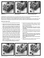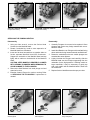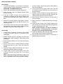
1
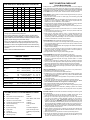
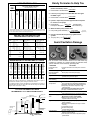
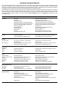
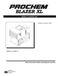
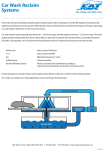
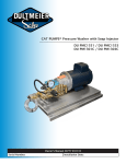
CP PLUNGER PUMP SERVICE MANUAL
®
3CP MODELS: 3CP1120, 3CP1130, 3CP1140
5CP MODELS: 5CP2120W, 5CP2140WCS, 5CP2150W, 5CP3120, 5CP3120G1, 5CP3130G1,
5CP5120, 5CP5150G1, 5CP6120, 5CP6120G1, 5CP6140, 5CP6150
7CP MODELS: 7CP6170
INSTALLATION AND START-UP INFORMATION
Optimum performance of the pump is dependent upon the entire liquid system and will be obtained only
with the proper selection, installation of plumbing, and operation of the pump and accessories.
SPECIFICATIONS: Maximum specifications refer to individual attributes. It is not
implied that all maximums can be performed simultaneously. If more than one
maximum is considered, check with your CAT PUMPS supplier to confirm the
proper performance and pump selection. Refer to individual pump Data Sheet for
complete specifications, parts list and exploded view.
LUBRICATION: Fill crankcase with special CAT PUMP oil per pump specifications
(3CP-10 oz., 5CP-17 oz., 7CP-38 oz.). DO NOT RUN PUMP WITHOUT OIL IN
CRANKCASE. Change initial fill after 50 hours running period. Thereafter, change
oil every 3 months or 500 hour intervals. Additional lubrication may be required
with increased hours of operation and temperature.
PUMP ROTATION: Pump was designed for forward rotation to allow optimum
lubrication of the crosshead area. Reverse rotation is acceptable if the crankcase oil
level is increased slightly above center dot to assure adequate lubrication.
PULLEY SELECTION: Select size of motor pulley required to deliver the desired
flow from Horsepower Requirement and Pulley Selection Chart (refer to Tech
Bulletin 003 or individual Data Sheet).
DRIVE SELECTION: The motor or engine driving the pump must be of adequate
horsepower to maintain full RPM when the pump is under load. Select the electric
motor from the Horsepower Requirement Chart according to required pump
discharge flow, maximum pressure at the pump and drive losses of approximately
3-5%. Consult the manufacturer of gas or diesel engine for selection of the proper
engine size.
MOUNTING: Mount the pump on a rigid, horizontal surface in a manner to permit
drainage of crankcase oil. An uneven mounting surface will cause extensive
damage to the pump base. To minimize piping stress, use appropriate flexible
hose to inlet and discharge ports. Use the correct belt; make sure pulleys are
aligned. Excessive belt tension may be harmful to the bearings. Hand rotate pump
before starting to be certain shaft and bearings are free moving.
LOCATION: If the pump is used in extremely dirty or humid conditions, it is
recommended pump be enclosed. Do not store or operate in excessively high
temperature areas or without proper ventilation.
INLET CONDITIONS: Refer to complete Inlet Condition Check-List in this manual
before starting system. DO NOT STARVE THE PUMP OR RUN DRY. Temperatures
above 130°F are permissible. Add 1/2 PSI inlet pressure per each degree F over
130°F. Elastomer or RPM changes may be required. See Tech Bulletin 002 or call
CAT PUMPS for recommendations.
C.A.T.: Installation of a C.A.T. (Captive Acceleration Tube) is recommended in
applications with stressful inlet conditions such as high temperatures, booster pump
feed, long inlet lines or quick closing valves.
DISCHARGE CONDITIONS: OPEN ALL VALVES BEFORE STARTING SYSTEM to
avoid deadhead overpressure condition and severe damage to the pump or system.
Install a Pulsation Dampener on the discharge head or in the discharge line as
close to the head as possible. Be certain the pulsation dampener (Prrrrr-o-lator) is
properly precharged for the system pressure (see individual Data Sheet).
A reliable Pressure Gauge should be installed near the discharge outlet of the high
pressure manifold. This is extremely important for adjusting pressure regulating
devices and also for proper sizing of the nozzle or restricting orifice. The pump is
rated for a maximum pressure; this is the pressure which would be read at the
discharge manifold of the pump, NOT AT THE GUN OR NOZZLE.
Use PTFE thread tape or pipe thread sealant (sparingly) to connect accessories or
plumbing. Exercise caution not to wrap tape beyond the last thread to avoid
tape from becoming lodged in the pump or accessories. This condition will cause a
malfunction of the pump or system.
PRESSURE REGULATION: All systems require both a primary pressure regulating
device (i.e., regulator, unloader) and a secondary pressure safety relief device
(i.e., pop-off valve, safety valve). The primary pressure device must be installed on
the discharge side of the pump. The function of the primary pressure regulating
device is to protect the pump from over pressurization, which can be caused by a
plugged or closed off discharge line. Over pressurization can severely damage the
pump, other system components and can cause bodily harm. The secondary safety
relief device must be installed in-line between the primary device and the pump or
on the opposite side of the manifold head. This will ensure pressure relief of the
system if the primary regulating device fails. Failure to install such a safely device
will void the warranty on the pump.
When the high pressure system is left running with the trigger gun off, the by-pass
liquid can be routed to drain or to the pump inlet. If routed to the pump inlet, the
by-pass liquid can quickly develop excessive heat and result in damage to the
pump. A THERMO VALVE installed in the by-pass line is recommended to protect
the pump. An AUTO SHUT-OFF ASSEMBLY may also be used.
NOZZLES: A worn nozzle will result in loss of pressure. Do not adjust pressure
regulating device to compensate. Replace nozzle and reset regulating device to
system pressure.
PUMPED LIQUIDS: Some liquids may require a flush between operations or before
storing. For pumping liquids other than water, contact your CAT PUMPS supplier.
STORING: For extended storing or between use in cold climates, drain all pumped
liquids from pump and flush with antifreeze solution to prevent freezing and
damage to the pump. DO NOT RUN PUMP WITH FROZEN LIQUID (refer to Tech
Bulletin 083).
WARNING
All systems require both a primary pressure regulating device (i.e., regulator, unloader) and a secondary pressure safety relief device (i.e., pop-off valve, safety valve).
Failure to install such relief devices could result in personal injury or damage to the pump or to system components. CAT PUMPS does not assume any liability or responsibility
for the operation of a customer’s high pressure system.
Products described hereon are covered by one or more of the following U.S. patents 3558244, 3652188, 3809508, 3920356, 3930756 and 5035580
CAT PUMPS (U.K.) LTD.
World Headquarters
CAT PUMPS
1681 - 94th Lane N.E. Minneapolis, MN 55449 - 4324
Phone (763) 780-5440 — FAX (763) 780-2958
e-mail: [email protected]
www.catpumps.com
®
The Pumps with Nine Lives
1 Fleet Business Park, Sandy Lane, Church Crookham, Fleet
Hampshire GU52 8BF, England
Phone Fleet 44 1252-622031 — Fax 44 1252-626655
e-mail: [email protected]
N.V. CAT PUMPS INTERNATIONAL S. A.
Heiveldekens 6A, 2550 Kontich, Belgium
Phone 32- 3- 450.71.50 — Fax 32-3- 450.71.51
e-mail: [email protected] www.catpumps.be
International Inquiries
CAT PUMPS DEUTSCHLAND GmbH
FAX (763) 785-4329
e-mail: [email protected]
Buchwiese 2, D-65510 Idstein, Germany
Phone 49 6126-9303 0 — Fax 49 6126-9303 33
e-mail: [email protected] www.catpumps.de
PN 33009 Rev H 12432
All Models
3CP1120, 5CP2120W, 7CP6170
5CP3120, 5CP5120, 5CP5150
Removal of Valve Plugs
Valve Plug and O-Ring
Valve Plug, O-Ring and Back-up Ring
CAUTION: Before commencing with service, shut off drive (electric motor, gas or diesel engine) and turn off water supply to
pump. Relieve all discharge line pressure by triggering gun or opening valve in discharge line.
After servicing is completed, turn on water supply to pump, start drive, reset pressure regulating device and secondary valve, read
system pressure on the gauge at the pump head. Check for any leaks, vibration or pressure fluctuations and resume operation.
SERVICING THE VALVES
1. Remove the hex Valve Plugs (top discharge, bottom inlet).
2. Examine the O-Ring under the plug for cuts or distortion.
Replace if worn. Lubricate new O-Rings before installing.
NOTE: The 5CP3120, 5CP5120 and 5CP5150 have
both an O-Ring and Back-up Ring on the Valve Plug.
3. Grasp Spring Retainer by the tab at the top with a
pliers and remove from each valve chamber. Usually
the valve assembly will remain together while being
removed. To separate the valve assembly, insert a
screw-driver into the side of the Spring Retainer and
press on the back side of the Valve to begin separation, then between the Spring Retainer and Seat to
separate completely. If the valve assembly separates
during removal, remove the Spring and Valve with a
needle nose pliers. With a reverse pliers, remove the
Seat from each valve chamber. Then, with a small
screwdriver, carefully remove the O-Ring at the bottom
of the valve chamber.
NOTE: The 5CP2120W, 5CP6120 and 7CP6170
have an O-Ring and Back-up Ring on each Seat.
4. Examine all valve parts for pitting, gouges or wear and
replace with preassembled Valve Assembly. Service
kit contains Spring Retainers, Springs, Valves, Seats,
Back-up Rings and O-Rings.
NOTE: Inlet and discharge valve parts are interchangeable. Two Valve Kits are needed for complete
valve change.
5. Grasp new Valve Assembly by the tab at the top with a
pliers, immerse in oil and push into each valve chamber. Be certain valve assembly is completely seated in
valve chamber.
NOTE: For certain applications apply liquid gasket
to the o-ring crevices and seal surfaces. See Tech
Bulletin 053 for model identification.
NOTE: EPDM elastomers require Silicone-base
lubricant.
6. Apply Loctite 242 to the threads of each Valve Plug,
thread into valve port and torque per chart.
3CP1120, 5CP2120W, 7CP6170
5CP3120, 5CP5120, 5CP5150
All Models
Removal of Valve Assembly
Removal of Valve Assembly
Removal of Valve Seat O-Ring
3CP1120, 5CP3120, 5CP5120
5CP2120W, 5CP6120, 7CP6170
All Models
Complete Valve Assembly
Complete Valve Assembly
Removal of Socket Head Screws
SERVICING THE PUMPING SECTION
Disassembly
Reassembly
1. Using an allen wrench, remove the Socket Head
Screws from the Manifold Head.
1. Generally Plungers do not need to be replaced. Clean
plungers and remove any foreign material with a nonabrasive cleaner.
2. Rotate Crankshaft by hand to start separation of
Manifold Head from Crankcase.
3. Insert two flat head screwdrivers on opposite sides to
further separate Manifold Head from Crankcase.
Support the underside of the Manifold Head and tap
lightly with a mallet on the backside of the Manifold
Head.
CAUTION: KEEP MANIFOLD PROPERLY ALIGNED
WITH CERAMIC PLUNGERS WHEN REMOVING TO
AVOID DAMAGE TO THE PLUNGERS.
4. Remove the Seal Retainer from each plunger rod and
examine for wear.
2. Install Seal Retainer over Plungers with small tab facing
down and holes facing forward towards manifold head.
3. Rotate the crankshaft so the two outside plungers are
extended the same distance.
4. Lightly lubricate the Plungers and carefully slide the
Manifold Head onto the Plungers supporting from the
underside. On the high pressure V-Packing models or
larger manifolds, it may be necessary to gently tap
with a soft mallet until the Manifold Head is flush with
the Crankcase.
5. Replace Socket Head Screws and torque per chart.
5. Examine Ceramic Plunger for cracks or scoring. Refer
to SERVICING THE PLUNGERS if replacement is
needed.
3CP1120, 5CP2120W, 5CP6120
5CP3120, 5CP5120, 5CP5150, 7CP6170
All Models except 7CP6170
Seal Arrangement
Seal Arrangement
Plunger Arrangement
SERVICING THE PLUNGERS
Disassembly
1. To service the plungers, it is necessary to remove the
manifold head. Follow disassembly procedure for
SERVICING THE PUMPING SECTION.
2. Remove the Seal Retainer from each plunger rod.
3. Using a wrench, loosen the Plunger Retainer about
three to four turns.
4. Push the Ceramic Plunger back towards the
crankcase to separate from the Plunger Retainer and
proceed with unthreading the Plunger Retainer by
hand.
5. Remove the Plunger Retainer, Seal Washer, Ceramic
Plunger, Keyhole Washer and Barrier Slinger from
each Plunger Rod.
6. On the model 7CP6170 remove the Plunger Retainer,
Stud, Gasket, O-Ring, Back-up Ring, Ceramic Plunger
and Barrier Slinger from each Plunger Rod.
Reassembly
1. Visually inspect Crankcase Oil Seals for deterioration
or leaks and contact factory for assistance with
replacement.
2. Replace Barrier Slinger if damaged and slide onto
Plunger Rod with concave side away from
Crankcase.
3. Examine Sealing Washer for cuts or wear and replace
as needed.
4. On the model 7CP6170 examine Gaskets, O-Rings
and Back-up Rings for cuts or wear and replace as
needed.
5. Examine Plunger Retainers and Studs for wear or
damaged threads and replace as needed.
6. On the model 7CP6170 install Gaskets first, then
O-Rings and Back-up Rings onto the Plunger
Retainer.
NOTE: Lubricate O-Rings and Back-up Rings for
ease in installation and to reduce possible damage.
7. All other models, lubricate and install Sealing Washer
onto Plunger Retainer.
8. On the model 7CP6170 apply Loctite 242 to one end
of threaded Plunger Retainer Stud and secure to
Plunger Retainer.
9. Examine Ceramic Plungers for scoring, scale build-up,
chips or cracks and replace as needed. Generally the
ceramic plungers do not need to be replaced.
10. Slide Plunger Retainer Assembly into flat end of
Ceramic Plunger.
11. Apply Loctite 242 to exposed threaded end of Plunger
Retainer.
12. Install Ceramic Plunger with Plunger Retainer onto
each Plunger Rod shoulder and thread Plunger Rod.
Torque to specifications per chart.
NOTE: Ceramic Plungers can only be installed in
one direction. Counterbore end of Ceramic
Plunger to fit over Plunger Rod shoulder.
13. Install Seal Retainers with small tabs facing down and
holes facing forward towards manifold head.
14. Proceed with servicing the seals or remounting of
Manifold Head as described.
SERVICING THE SEALS AND V-PACKINGS
Disassembly
Hi-Pressure Seal Models:
1. Remove the Manifold Head as described in SERVICING
THE PUMPING SECTION.
1. Lubricate each seal chamber in manifold head.
2. Place the Crankcase side of manifold facing up and
with a reverse pliers, remove the Lo-Pressure Seal
from the Seal Case.
3. Using a reverse pliers, remove the press-in style Seal
Case from the Manifold Head.
4. Remove the O-Ring from O.D. of Seal Case.
5. Hi-Pressure Seal Models: The Hi-Pressure Seal is
generally easily removed from the manifold without
any tools. If extremely worn, a reverse pliers may be
used.
6. V-Packing Models: The V-Packings and Male
Adapter are easily removed from the manifold without
any tools.If extremely worn, a reverse pliers may be
used.
Reassembly
NOTE: If your pump has been built with special
seals and O-Rings, service with same type. Refer
to pump Data Sheet for correct parts or kits.
V-Packing Models:
1. Lubricate each seal chamber in manifold head.
NOTE: For certain applications apply liquid gasket
to the O-Ring crevices and seal surfaces. See Tech
Bulletin 053 for model identification.
NOTE: EPDM elastomers require silicone-base
lubricant.
2. Insert Male Adapter with notches down and “v” side
up and press completely into each seal chamber by
hand.
3. Lubricate V-Packings and install one at a time with
grooved side down into each seal chamber.
4. Examine Seal Case O-Ring and replace if worn.
Lubricate new O-Rings before installing.
5. Press Seal Case into each seal chamber until completely
seated.
NOTE: For certain applications apply liquid gasket
to the O-Ring crevices and seal surfaces. See Tech
Bulletin 053 for model identification.
NOTE: EPDM elastomers require silicone-base
lubricant.
2. Carefully square Hi-Pressure Seal into position by
hand with the grooved side down (metal back facing
out) and press into each seal chamber until completely
seated.
3. Examine Seal Case O-Rings and replace if worn.
Lubricate new O-Ring before installing.
4. Press the Seal Case into each seal chamber until
completely seated.
Lo-Pressure Seal-All Models:
1. Examine Lo-Pressure Seals for wear to the internal
ridges, outer surfaces or for broken springs and replace as needed.
2. Install Lo-Pressure Seal into Seal Case with garter
spring down.
3. All Models: Install Seal Retainer over Plungers with
small tabs facing down and holes facing forward
towards manifold head.
4. Replace Manifold Head onto pump as described under
SERVICING THE PUMPING SECTION and torque per
chart.
SERVICING THE CRANKCASE SECTION
1. While Manifold Head, Plungers and Seal Retainers are
removed, examine Crankcase Oil Seals for leaking
and wear.
2. Check for any signs of leaking at Rear Cover, Drain
Plug, Bubble Gauge and Dipstick (7CP6170).
3. Check oil level and for evidence of water in oil.
Change crankcase oil on a regular schedule. See
Preventative Maintenance Check-List.
4. Rotate Crankshaft by hand to feel for smooth bearing
movement.
5. Examine Crankshaft Oil Seal externally for drying,
cracking or leaking.
6. Contact CAT PUMPS or your local distributor if
crankcase service is evidenced.
INLET CONDITION CHECK-LIST
PREVENTATIVE MAINTENANCE CHECK-LIST
Check
Daily Weekly 50 hrs. 500 hrs.* 1500 hrs.** 3000 hrs.**
Clean Filters
x
Oil Level/Quality
x
Oil Leaks
x
Water Leaks
x
Belts, Pulley
x
Plumbing
x
Initial Oil Change
x
Oil Change
x
Seal Change
x
Valve Change
x
Accessories
x
* If other than CAT PUMPS special multi-viscosity ISO68 oil is used,
change cycle should be every 300 hours.
** Each system’s maintenance cycle will be exclusive. If system performance decreases, check immediately. If no wear at 1500 hours, check
again at 2000 hours and each 500 hours until wear is observed. Valves
typically require changing every other seal change.
Duty cycle, temperature, quality of pumped liquid and inlet feed
conditions all effect the life of pump wear parts and service cycle.
** Remember to service the regulator/unloader at each seal servicing
and check all system accessories and connections before resuming
operation.
Refer to video for additional assistance.
TORQUE CHART
Pump Item
Pump Model
Torque
in. lbs. ft. lbs. Nm
Thread
Tool Size [P/N]
Plunger Retainer
M6
M10 Hex [25082]
55
4.4 6.2
Manifold Screw
M8
M6 Allen [30941]
115
9.58 13
Valve Plugs
3CP, 5CP
7CP
M22
M26
M24 Hex [44046]
M27 Hex [44045]
870
870
72.5 98
72.5 98
Bearing Cover Screws
3CP
5CP, 7CP
M6
M8
M10 Hex./Phil. [25082]
M13 Hex [25324]
50
115
4.0 5.4
9.58 13
Rear Cover Screws
M6
M10 Hex./Phil. [25082]
50
4.0 5.4
Connecting Rod Screws
M7
M10 Hex [25082}
95
8.0
11
Bubble Oil Gauge
M28 Oil Gauge Tool [44050]
45
3.8
5
Direct Mount Bolts
M8
115
9.58 13
M13 Hex [25324]
TECHNICAL BULLETIN REFERENCE CHART
No.
Subject
002
Inlet Pressure VS Liquid Temperature
Models
All Models
003
Power Unit Drive Packages
3PFR - 68PFR, 10FR - 60FR
024
Lubrication of Lo-Pressure Seals
All Models
036
Cylinder and Plunger Reference Chart
All Models
043
LPS and HPS Servicing
All Plunger Models
060
Baffle Assembly
34170
064
By-Pass Hose Sizing
All Unloaders/Regulators
074
Torque Chart
Piston and Plunger Pumps
077
Oil Drain Kit
All Models (except 2SF/4SF)
078
Field Retrofit Mounting
5CP
083
Winterizing a Pump
All Models
Review Before Start-Up
Inadequate inlet conditions can cause serious malfunctions in the best designed
pump. Surprisingly, the simplest of things can cause the most severe problems or go
unnoticed to the unfamiliar or untrained eye. REVIEW THIS CHECK-LIST BEFORE
OPERATION OF ANY SYSTEM. Remember, no two systems are alike, so there can
be no ONE best way to set-up a system. All factors must be carefully considered.
INLET SUPPLY should exceed the maximum flow being delivered by the pump to
assure proper performance.
❏ Open inlet shut-off valve and turn on water supply to avoid starving pump. DO
NOT RUN PUMP DRY.
❏ Temperatures above 130°F are permissible. Add 1/2 PSI inlet pressure per each
degree F over 130°F. Elastomer or RPM changes may be required. See Tech
Bulletin 002 or call CAT PUMPS for recommendations.
❏ Avoid closed loop systems especially with high temperature, ultra-high pressure
or large volumes. Conditions vary with regulating/unloader valve.
❏ Low vapor pressure liquids, such as solvents, require a booster pump and C. A.T.
to maintain adequate inlet supply.
❏ Higher viscosity liquids require a positive head and a C. A.T. to assure adequate
inlet supply.
❏ Higher temperature liquids tend to vaporize and require positive heads and
C. A.T. to assure adequate inlet supply.
❏ When using an inlet supply reservoir, size it to provide adequate liquid to
accommodate the maximum output of the pump, generally a minimum of 6-10
times the GPM (however, a combination of system factors can change this
requirement); provide adequate baffling in the tank to eliminate air bubbles and
turbulence; install diffusers on all return lines to the tank.
INLET LINE SIZE should be adequate to avoid starving the pump.
❏ Line size must be a minimum of one size larger than the pump inlet fitting. Avoid
tees, 90 degree elbows or valves in the inlet line of the pump to reduce the risk of
flow restriction and cavitation.
❏ The line MUST be a FLEXIBLE hose, NOT a rigid pipe, and reinforced on SUCTION
systems to avoid collapsing.
❏ The simpler the inlet plumbing the less the potential for problems. Keep the
length to a minimum, the number of elbows and joints to a minimum (ideally no
elbows) and the inlet accessories to a minimum.
❏ Use pipe sealant to assure air-tight, positive sealing pipe joints.
INLET PRESSURE should fall within the specifications of the pump.
❏ Acceleration loss of liquids may be increased by high RPM, high temperatures,
low vapor pressures or high viscosity and may require pressurized inlet
and C. A.T. to maintain adequate inlet supply. DO NOT USE C.A.T. WITH
SUCTION INLET.
❏ Optimum pump performance is obtained with +20 PSI (1.4 BAR) inlet pressure
and a C. A.T. for certain applications. With adequate inlet plumbing, most pumps
will perform with flooded suction. Maximum inlet pressure is 60 PSI (4 BAR).
❏ After prolonged storage, pump should be rotated by hand and purged of air to
facilitate priming. Disconnect the discharge port and allow liquid to pass through
pump and measure flow.
INLET ACCESSORIES are offered to protect against over pressurization,
contamination or temperature and control flow.
❏ A shut-off valve is recommended to facilitate maintenance.
❏ Installation of a C. A.T. is essential in applications with stressful conditions such
as high temperatures, booster pump feed or long inlet lines. Do not use C. A.T.
with negative inlet pressure.
❏ A stand pipe can be used in some applications to help maintain a positive head
at the pump inlet line.
❏ Inspect and clean inlet filters on a regular schedule to avoid flow restriction.
❏ A pressure transducer is necessary to accurately read inlet pressure. Short
term, intermittent cavitation will not register on a standard gauge.
❏ All accessories should be sized to avoid restricting the inlet flow.
❏ All accessories should be compatible with the solution being pumped to prevent
premature failure or malfunction.
❏ Optional inlet protection can be achieved by installing a pressure cut off switch
between the inlet filter and the pump to shut off pump when there is no positive
inlet pressure.
BY-PASS TO INLET Care should be exercised when deciding the method of by-pass
from control valves.
❏ It is recommended the by-pass be directed to a baffled reservoir tank, with at
least one baffle between the by-pass line and the inlet line to the pump.
❏ Although not recommended, by-pass liquid may be returned to the inlet line
of the pump if the system is properly designed to protect your pump. When a
pulsation dampener is used, a PRESSURE REDUCING VALVE must be
installed on the inlet line (BETWEEN THE BY-PASS CONNECTION AND THE
INLET TO THE PUMP) to avoid excessive pressure to the inlet of the pump. It is
also recommended that a THERMO VALVE be used in the by-pass line to monitor the temperature build-up in the by-pass loop to avoid premature seal failure.
❏ A reinforced, flexible, low pressure hose rated up to 300 PSI should be used for
routing by-pass back to the pump inlet.
❏ Caution should be exercised not to undersize the by-pass hose diameter and
length. Refer to Technical Bulletin 064 for additional information on the size and
length of the by-pass line.
❏ Check the pressure in the by-pass line to avoid over pressurizing the inlet.
❏ The by-pass line should be connected to the pump inlet line at a gentle angle of
45° or less and no closer than 10 times the pump inlet port diameter e.g. 1-1/2"
port size = 15" distance from pump inlet port.
Handy Formulas to Help You
HOSE FRICTION LOSS
PRESSURE DROP IN PSI PER 100 FT OF HOSE
WITH TYPICAL WATER FLOW RATES
Hose Inside Diameters, Inches
Water*
Flow
Gal/Min
1/4
5/16
3/8
1/2
5/8
3/4
1"
0.5
16
5
2
1
54
20
7
2
2
180
60
25
6
2
3
380
120
50
13
4
2
4
220
90
24
7
3
5
320
130
34
10
4
6
220
52
16
7
1
8
300
80
25
10
2
10
450
120
38
14
3
15
900
250
80
30
7
20
1600
400
121
50
12
25
650
200
76
19
30
250
96
24
40
410
162
42
50
600
235
62
60
370
93
*At a fixed flow rate with a given size hose, the pressure drop across a given hose length
will be directly proportional. A 50 ft. hose will exhibit one-half the pressure drop of a 100
ft. hose. Above values shown are valid at all pressure levels.
WATER LINE PRESSURE LOSS
PRESSURE DROP IN PSI PER 100 FEET
Steel Pipe—Nominal Dia.
Water
GPM
Brass Pipe—Nominal Dia.
1/4 3/8 1/2 3/4 1 11/4 11/2
Copper Tubing O.D. Type L
1/4 3/8 1/2 5/8 3/4 7/8
8.5 1.9
6.0 1.6
120 13 2.9 1.0
30 7.0 2.1
20 5.6 1.8
400 45 10 3.4 1.3
60 14 4.5 1.1
40 11 3.6
94 20 6.7 2.6
1/4 3/8 1/2 3/4
1
2
3
5
8
10
15
25
40
1 1 /4 1 /2
1
1
150 36 12 2.8
100 28 9.0 2.2
230 50 17 6.1 3.0
330 86 28 6.7 1.9
220 62 21 5.2 1.6
500 120 40 15 6.5
520 130 43 10 3.0
320 90 30 7.8 2.4
180 56 22 10
270 90 21 6.2 1.6
190 62 16 5.0 1.5
120 44 20
670 240 56 16 4.2 2.0
470 150 40 12 3.8 1.7
330 110 50
66 17 8.0
39 11 5.0
550 200 88
37
17
23
11
52
29
40
19
210 107
48
61
28
60
80
100
RESISTANCE OF VALVES AND FITTINGS
Nominal
Pipe
Inside
Size
Diameter
Inches
Inches
Equivalent Length of Standard Pipe in Feet
Gate
Valve
Globe
Valve
Angle
Valve
45˚
Elbow
90˚
Elbow
180˚
Close
Ret
Tee
Thru
Run
Tee
Thru
Branch
1/2
3/4
1
11/4
11/2
0.622
0.824
1.049
1.380
1.610
0.41
0.54
0.69
0.90
1.05
18.5
24.5
31.2
41.0
48.0
9.3
12.3
15.6
20.5
24.0
0.78
1.03
1.31
1.73
2.15
1.67
2.21
2.81
3.70
4.31
3.71
4.90
6.25
8.22
9.59
0.93
1.23
1.56
2.06
2.40
3.33
4.41
5.62
7.40
8.63
2
2.067
2.469
3.068
4.026
1.35
1.62
2.01
2.64
61.5
73.5
91.5
120.0
30.8
36.8
45.8
60.0
2.59
3.09
3.84
5.03
5.55
6.61
8.23
10.80
12.30
14.70
18.20
23.90
3.08
3.68
4.57
6.00
11.60
13.20
16.40
21.60
2 1/2
3
4
Arriving at a total line pressure loss, consideration should then be given to
pressure loss created by valves, fittings and elevation of lines.
If a sufficient number of valves and fittings are incorporated in the system to
materially affect the total line loss, add to the total line length, the equivalent
length of line of each valve or fitting.
TYPICAL RESERVOIR TANK
RECOMMENDED 6 TO 10 TIMES SYSTEM CAPACITY
Supply Line
Bypass Line
(from regulator or unloader)
→
D
→
→
→
→
→
MIN. 4"
(Dia of pipe)
T
X
Level Sensing
Device
→
1.5 x D (Min.)
Flexible Hose
to Pump
→
→
FILTER
MIN. 4"
Minimum
Liquid
Level
Bypass Line
(from regulator or
unloader)
Minimum Two Baffles
Sealed at Bottom
Q. How can I find the RPM needed to get specific GPM
(Gallons Per Minute) I want?
Rated RPM
A. Desired RPM = Desired GPM x
Rated GPM
Q. I have to run my pump at a certain RPM. How do I figure
the GPM I’ll get?
Rated GPM
A. Desired GPM = Desired RPM x
Rated RPM
Q. Is there a simple way to find the approximate horsepower
I’ll need to run the pump?
A. Electric Brake
GPM x PSI
=
Horsepower Required
1460
(Standard 85%
Mech. Efficiency)
Q. What size motor pulley should I use?
Pump RPM
A. Pump Pulley (Outer Diameter) x
Motor/Engine RPM
(Consult
Engine Mfr.)
Q. How do I calculate the torque for my hydraulic drive
system?
GPM x PSI
A. Torque (ft. lbs.) = 3.6
RPM
(
)
Avoid Cavitation Damage
One or several of the conditions shown in the chart below may
contribute to cavitation in a system resulting in premature wear,
system downtime and unnecessary operating costs.
CONDITION
Inadequate inlet
line size
Water hammering
liquid acceleration/
deacceleration
Rigid Inlet Plumbing
Excessive Elbows in
Inlet Plumbing
Excessive Liquid
Temperature
SOLUTION
Increase line size to the inlet port or one size
larger
● Install C.A.T. Tube
● Move pump closer to liquid supply
●
Use flexible wire reinforced hose to absorb
pulsation and pressure spikes
● Keep elbows to a minimum and less than 90°
●
Use Thermo Valve in bypass line
Do not exceed pump temperature specifications
● Substitute closed loop with baffled holding tank
● Adequately size tank for frequent or high
volume bypass
● Pressure feed high temperature liquids
● Properly ventilate cabinets and rooms
Air Leaks in Plumbing ● Check all connections
● Use PTFE thread tape or pipe thread sealant
● Size tank according to pump output —
Agitation in Supply
Tank
Minimum 6-10 times system GPM
● Baffle tank to purge air from liquid and
separate inlet from discharge
High Viscosity Liquids ● Verify viscosity against pump specifications
before operation
● Elevate liquid temperature enough to reduce
viscosity
● Lower RPM of pump
● Pressure feed pump
● Increase inlet line size
● Perform regular maintenance or use clean
Clogged Filters
filters to monitor build up
● Use adequate mesh size for liquid and pump
specifications
●
●
DIAGNOSIS AND MAINTENANCE
One of the most important steps in a high pressure system is to establish a regular maintenance program. This will vary slightly with each
system and is determined by various elements such as the duty cycle, the liquid being pumped, the actual specifications vs rated specifications
of the pump, the ambient conditions, the inlet conditions and the accessories in the system. A careful review of the necessary inlet conditions
and protection devices required before the system is installed will eliminate many potential problems.
CAT PUMPS are very easy pumps to service and require far less frequent service than most pumps. Typically, only common tools are required,
making in-field service convenient, however, there are a few custom tools, special to certain models, that do simplify the process. This service
manual is designed to assist you with the disassembly and reassembly of your pump. The following guide will assist in determining the cause
and remedy to various operating conditions. You can also review our FAQ or SERVICE sections on our WEB SITE for more facts or contact
CAT PUMPS directly.
PROBLEM
PROBABLE CAUSE
SOLUTION
Low pressure
•Worn nozzle.
•Belt slippage.
•Air leak in inlet plumbing.
•Pressure gauge inoperative or not registering accurately.
•Relief valve stuck, partially plugged or improperly adjusted.
•Inlet suction strainer (filter) clogged or improperly sized.
•Abrasives in pumped liquid.
•Leaky discharge hose.
•Inadequate liquid supply.
•Severe cavitation.
•Worn seals.
•Worn or dirty inlet/discharge valves.
•Replace with properly sized nozzle.
•Tighten belt(s) or install new belt(s).
•Tighten fittings and hoses. Use PTFE liquid or tape.
•Check with new gauge. Replace worn or damaged gauge.
•Clean/adjust relief valve. Replace worn seats/valves and o-rings.
•Clean filter. Use adequate size filter. Check more frequently.
•Install proper filter.
•Replace discharge hose with proper rating for system.
•Pressurize inlet and install C.A.T.
•Check inlet conditions.
•Install new seal kit. Increase frequency of service.
•Clean inlet/discharge valves or install new valve kit.
Pulsation
•Faulty Pulsation Dampener.
•Foreign material trapped in inlet/discharge valves.
•Check precharge. If low, recharge, or install a new dampener.
•Clean inlet/discharge valves or install new valve kit.
•Worn V-Packings, Hi-Pressure or Lo-Pressure Seals.
•Worn adapter o-rings.
•Humid air condensing into water inside the crankcase.
•Excessive wear to seals and V-Packings.
•Install new seal kit. Increase frequency of service.
•Install new o-rings.
•Install oil cap protector. Change oil every 3 months or 500 hours.
•Install new seal kit. Increase frequency of service.
Knocking noise
•Inlet supply
•Bearing
•Pulley
•Inadequate inlet liquid supply.
•Broken or worn bearing.
•Loose pulley on crankshaft
•Check liquid supply. Increase line size, pressurize or install C.A.T.
•Replace bearing.
•Check key and tighten set screw.
Oil leak
•Crankcase oil seals.
•Crankshaft oil seals and o-rings.
•Drain plug
•Bubble gauge
•Rear cover
•Filler cap
•Worn crankcase oil seals.
•Worn crankshaft oil seals or o-rings on bearing cover.
•Loose drain plug or worn drain plug o-ring.
•Loose bubble gauge or worn bubble gauge gasket.
•Loose rear cover or worn rear cover o-ring.
•Loose filler cap or excessive oil in crankcase.
•Replace crankcase oil seals.
•Remove bearing cover and replace o-rings and/or oil seals.
•Tighten drain plug or replace o-ring.
•Tighten bubble gauge or replace gasket.
•Tighten rear cover or replace o-ring.
•Tighten filler cap. Fill crankcase to specified capacity.
Pump runs extremely rough
•Inlet conditions
•Pump valves
•Pump seals
•Restricted inlet or air entering the inlet plumbing
•Stuck inlet/discharge valves.
•Leaking V-Packings, Hi-Pressure or Lo-Pressure seals.
•Correct inlet size plumbing. Check for air tight seal.
•Clean out foreign material or install new valve kit.
•Install new seal kit. Increase frequency of service.
•Scored plungers.
•Over pressure to inlet manifold.
•Abrasive material in the liquid being pumped.
•Excessive pressure and/or temperature of pumped liquid.
•Running pump dry.
•Starving pump of adequate liquid.
•Replace plungers.
•Reduce inlet pressure per specifications.
•Install proper filtration at pump inlet and clean regularly.
•Check pressure and inlet liquid temperature.
•DO NOT RUN PUMP WITHOUT LIQUID.
•Increase hose one size larger than inlet port size. Pressurize and
install C.A.T.
•Replace manifold. Check liquid compatibility.
Water leak
•Under the manifold
•Into the crankcase
Premature seal failure
•Eroded manifold.