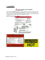
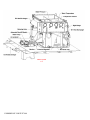
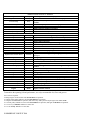
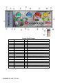
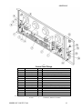
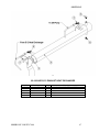
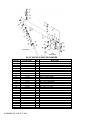
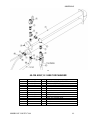
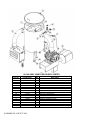
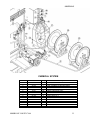
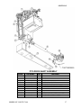
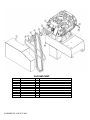
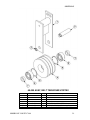
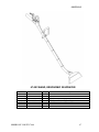
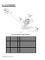
1
VORTEX 7000 MANUAL
Congratulations on your purchase of the
VORTEX MOBILE CLEANING UNIT.
This instruction/parts manual is a guide for
operating and servicing your BLUELINE
VORTEX 7000® mobile cleaning unit.
Proper operation and service are necessary to
ensure the outstanding performance of this unit.
When properly maintained, your mobile cleaning
unit will have a long and trouble-free life.
The following service methods outlined in this
manual are detailed in a manner that operation and
servicing may be performed properly and safely.
Because service levels vary due to the skill of the
mechanic, tools and parts availability, ensure that
prior to attempting any repair, you are familiar with
this equipment and have the proper tools. Any
questions regarding the operation, service, or repair
of this unit should be directed to your nearest
BLUELINE dealer.
The headings WARNING and CAUTION are
utilized to warn you that steps must be taken to
prevent personal injury or damage to the
equipment. Please make sure that you have read
and understand these instructions entirely before
proceeding with the operation of this unit.
Record your units vehicle identification number
here for future reference or if you should need to
contact the factory in the future for any reason.
VIN:
This service and operations manual is written
specifically for BLUELINE VORTEX 7000®
mobile
s cleaning unit manufactured by:
BLUELINE EQUIPMENT LLC
2604 Liberator Drive
Prescott, AZ 86301
USA
The information contained in this document is
subject to change without notice and does not
represent a commitment on the part of BLUELINE
EQUIPMENT LLC.
All rights reserved. Copyright 2006 by
BLUELINE EQUIPMENT LLC. No part of this
work may be used or reproduced in any form or
means without the express written consent and
permission of BLUELINE EQUIPMENT LLC.
Published by BLUELINE EQUIPMENT LLC.
First printing: October 2006
Printed in USA
VORTEX 7000® MANUAL
PART# 49-027
October 06
BLUELINE VORTEX 7000
I
LIMITED WARRANTY
BLUELINE warrants your machine to be free of defects in material and workmanship. This
warranty shall extend to the designated parts for the specific period of time listed from the date
of delivery to the user. If BLUELINE receives notice of any defects during the warranty period,
BLUELINE will either, at its option, repair or replace products that prove to be defective. Any
transportation, related service labor, normal maintenance and diagnostic calls are not included.
Vacuum Pump (Through manufacturer or local dealer)_______ 18 months
Water Pump_________________________________________ 1 year
Oil Pump___________________________________________ 1 year
Waste Pump_________________________________________ 1 year
Engine Heat Exchanger________________________________ 1 year
Wands (Excluding shut off valve and orifices)______________ 1 year
Waste and Water Tanks________________________________ 1 year
Pressure Regulator____________________________________ 1 year
All Other Components_________________________________ 1 year
This warranty shall not apply to defects caused by improper operation, inadequate maintenance
by the customer, unauthorized modification or misuse, improper repair, freezing or damage due
to hard water scaling.
Electrical components, disposable filters, belts, hoses, fittings, o-rings and other service
maintenance items are not under warranty. Components supplied by BLUELINE, but provided
by other manufacturers, will only be warranted to the extent that they are warranted to
BLUELINE.
To receive warranty service, products must be returned to a BLUELINE designated service
facility. The customer shall prepay shipping charges for products returned to BLUELINE for
warranty evaluation and BLUELINE shall pay for the return of products to the customer.
BLUELINE makes no other warranty, expressed or implied, with respect to this product.
BLUELINE disclaims the implied warranties of merchantability and fitness for a particular
purpose. Any implied warranty of merchantability or fitness is limited to the specific duration of
this limited warranty.
This warranty gives the customer specific legal rights, and you may also have other rights that
may vary from state to state, or province to province.
The remedies provided herein are the customer’s sole and exclusive remedies. In no event shall
BLUELINE be liable for any direct, indirect, special, incidental, or consequential damages,
whether based on contract, tort, or any other legal theory.
II BLUELINE VORTEX 7000
Table of Contents
SECTION ONE: GENERAL INFORMATION
1
1. SAFETY
Safety, Specifications, Chemical, Water Requirements
2
2. RECEIVING YOUR MOBILE CLEANING UNIT
Dealer Responsibility, Acceptance of Shipment, Equipment Listing, Optional Equipment
6
SECTION TWO: SYSTEMS/OPERATION
8
3. SYSTEMS
Water Pumping System, Heat Transfer System, Vacuum System, Chemical System
11
4. OPERATION
Equipment setup, Instrumentation, Starting Your Unit, Priming the Chemical Pump, Waste
Pump, Operation, Cleaning, Upholstery Cleaning, Stair Tool Cleaning, Flood Restoration,
Shut Down and Daily Maintenance, Freeze Protection.
15
SECTION THREE: MAINTENANCE and SERVICE
24
MAINTENANCE CHART
5. MAINTENANCE
6. GENERAL SERVICE ADJUSTMENTS
7. TROUBLESHOOTING
26
27
31
34
SECTION FOUR: PARTS and ACCESSORIES
39
9. ILLUSTRATED PARTS LISTINGS
10. ACCESSORIES
BLUELINE VORTEX 7000
40
68
III
SECTION 1:
GENERAL INFORMATION
1. SAFETY
Safety
Specifications
Chemical requirements
Water requirements
2
5
6
6
2. RECEIVING YOUR TRUCK MOUNT UNIT
Dealer responsibility
Acceptance of shipment
Equipment listing
Optional equipment
BLUELINE VORTEX 7000
6
6
7
7
1
1. SAFETY
For Your Safety!
The following WARNING labels are on your VORTEX 7000 mobile cleaning unit. These
labels point out important Warnings and Cautions, which must be followed at all times.
Failure to follow warnings could result in personal injury, fatality, to yourself and/or others
or property damage. Please follow these instructions carefully!
DO NOT remove these decals.
2 BLUELINE VORTEX 7000
SECTION 1
!
1. Read the operator's manual before
starting this unit.
Failure to adhere to instructions could result in
severe personal injury, property damage, or
could be fatal.
2. Operate this mobile cleaning only in a
well- ventilated area.
Exhaust fumes contain carbon monoxide,
which is an odorless and deadly poison that can
cause severe injury or death. DO NOT run this
unit in an enclosed area. DO NOT operate this
unit where the exhaust may enter a building
doorway, window, vent or other opening.
3. DO NOT place hands, feet, hair, clothing or
any body parts near rotating or moving parts.
Rotating machinery can cause severe injury or
death.
4. NEVER operate this unit without belt and
safety guards. High speed moving parts, such
as belts and pulleys, should be avoided while
the unit is running. Severe injury, fatality or
damage may result.
5. NEVER service this unit while it is running.
High speed mechanical parts as well as high
temperature components may result in injury or
severed limbs.
6. The engine and other components will be
extremely hot from operation. To prevent
severe burns, DO NOT touch these areas while
the unit is running or shortly after the unit is
shut off.
7. DO NOT touch the exhaust diverter valve or
any part of the exhaust system while the system
is running or for 20 minutes after the unit is
shut off. Severe burns could result.
personal injury, or fatality. Shut down unit,
allow to cool down and relieve system of all
pressure before removing caps, valves, plugs,
fittings, filters or hardware.
9. Battery acid contains sulfuric acid. To
prevent acid burns, avoid contact with skin,
eyes and clothing. Batteries also produce
explosive hydrogen gases while charging. To
prevent fire or explosion, charge batteries only
in a well ventilated area. Keep sparks, open
flames, as well as other sources of ignition
away from battery at all times. Remove all
jewelry prior to servicing batteries. Keep
batteries out of the reach of children.
Before disconnecting the negative (-) ground
cable, ensure that all switches are in the off
position. If on, a spark could occur at the
ground connection terminal which could cause
an explosion if hydrogen gas or gasoline
vapors are present. ALWAYS disconnect the
negative (-) terminal first.
10. DO NOT exceed your vehicles weight
limit. GVW (UD 1400) 14,250 lbs. This will
prevent unsafe or hazardous driving conditions.
11. Always keep your vehicle clean and
orderly. Wands, tools and accessories must be
securely stowed while driving the vehicle.
12. All high-pressure hoses must be rated at
3000 PSI and have a heat rating of 300° F.
Thermoplastic hoses do not meet this criteria,
and should never be used. Severe burns,
damage to property or fatality could result if
hoses do not meet these requirements.
13. Ensure that you have received proper
training from the distributor that you purchased
the unit from prior to operation.
14. This unit produces high pressure and high
temperatures. Improper use could result in
serious injury or fatality.
8. Water under high pressure at high
temperature can cause burns, severe
BLUELINE VORTEX 7000
3
15. DO NOT modify this unit in any manner.
Any modification could result in serious injury
or fatality.
16. California Proposition 65 Warning: Engine
exhaust from this product contains chemicals
known by the State of California to cause
cancer, birth defects, or other reproductive
harm.
4 BLUELINE VORTEX 7000
SECTION 1
SPECIFICATIONS
Truck
Nissan UD1400C
Allowable Truck Gross Weight
UD 1400C 14,250 lbs.
*Refer to owners’ manual for allowable axle load ratings.
Engine Speed
700-1700 rpm (Manual Control Cleaning Mode)
600-700 rpm (Idle)
Water Pump RPM
Vacuum Pump RPM
Water Flow Rate
Water Pump Pressure
Vacuum Relief Valve
Waste Tank Capacity
1550 rpm
3000 max rpm @ 1,127 cfm
6.5 GPM (maximum) Optional 4.5 GPM
1750 PSI (maximum) Optional 2750 PSI
17 in. HG
110 Gallons at shutoff
TANKS
Fresh Water
Waste Recovery
220 Gallons.
110 Gallons
JET SIZING
BLUELINE recommends that the total floor tool tip size does not exceed .06”. Using
larger jet sizes on your VORTEX 7000® unit may reduce cleaning temperatures.
Example: Four-jet wand uses four 95015 jets. (95 deg. Spray angle w/015 orifice)
.015 x 4 = .06
When using two wands while cleaning with this unit, BLUELINE recommends that the
tip size in each tool does not exceed a total of .040”.
Example: Four-jet wand uses four 9501 jets. (95 deg. Spray angle w/01 orifice)
.01 x 4 = .04 .04 x 2 tools = .08
Upholstery tool jet size: 80015
Stair tool jet size: 9502
Spray lance jet size: 3.5 GPM maximum
BLUELINE VORTEX 7000
5
FUEL REQUIREMENTS
Use ultra low sulfur diesel fuel (15ppm) ONLY.
Refer to vehicle owners' manual for use of additives
and bio-diesel recommendations.
ENGINE OIL REQUIREMENTS
Refer to vehicle owners' manual for recommended
oil type and maintenance schedules.
CHEMICAL REQUIREMENTS
The BLUELINE VORTEX 7000® mobile truck
cleaning unit’s unique last step chemical injection
system can be used with a wide variety of water
diluted chemical compounds, either acidic or
alkaline, depending on the work to be performed.
We recommend using only the highest quality
chemistry.
WATER REQUIREMENTS
Because hard water deposits will damage the
plumbing and heat exchange systems on this unit,
BLUELINE recommends that a high quality water
softener be used in areas where the water hardness
exceeds 3-1/2 grains. If a water softener is used, it
must have a flow capacity of at least five (5) GPM
or greater, without any hose constrictions.
The use of a water softening system will reduce
maintenance and reduce down time caused by hard
water scaling. It will also enhance the performance
of cleaning chemicals, which will result in greater
efficiency in lower concentrations.
2. RECEIVING YOUR
TRUCK CLEANING UNIT
DEALER RESPONSIBILITY
THE BLUELINE DEALER THAT YOU
PURCHASED THIS MOBILE TRUCK
CLEANING UNIT FROM IS RESPONSIBLE
FOR THE PROPER INITIAL TRAINING OF
YOUR OPERATORS AND MAINTENANCE
PERSONNEL.
ACCEPTANCE OF SHIPMENT
Your VORTEX 7000® mobile truck cleaning unit
was thoroughly tested, checked and inspected in its
entirety prior to leaving our manufacturing facility.
When receiving your mobile cleaning unit, please
make the following acceptance check:
1. The unit should not show any signs of damage. If
there is damage, notify your dealer immediately.
2. Carefully check your equipment and packing list.
The standard BLUELINE VORTEX 7000® unit
should arrive with the following items as well as
any optional accessories:
6 BLUELINE VORTEX 7000
SECTION 1
EQUIPMENT LISTING
A. Operation and Service manual
B. Carpet wand
C. Hose reel
D. 400 ft. 2” vacuum hose
E. 220 Gallon fresh water tank
F. 110 Gallon waste tank
G. Pre-Filter box with stainless steel strainer.
H. Waste tank filters.
I. 2 Chemical solution reels.
J. 400 ft. of 1/4 in. high pressure solution hose with
quick connects
K. 2 vacuum hose connectors
L. 50 ft. water supply hose with quick connect
M. Vortex marketing materials package.
OPTIONAL EQUIPMENT
BLUELINE VORTEX 7000
7
SECTION 2:
SYSTEMS/OPERATION
3 SYSTEMS/OPERATION
Mobile Truck Unit Layout
Battery
Fire extinguisher
9
10
10
3. SYSTEMS
Water pumping system
Heat transfer system
Vacuum system
Chemical pumping system
11
11
13
14
4. OPERATION
Preparation
Starting the unit
Priming the chemical pump
Automatic waste pump
Operation
Cleaning
Upholstery cleaning
Stair tool cleaning
Flood restoration/extraction
Shut down and daily maintenance
Freeze protection
8 BLUELINE VORTEX 7000
15
19
20
20
21
21
21
22
22
22
23
BLUELINE VORTEX 7000
9
BATTERY CONNECTION
!
Explosive gases, Dangerous gases!
Batteries contain sulfuric acid. To prevent acid
burns, avoid contact with skin, eyes and
clothing. Batteries also produce explosive
hydrogen gases while charging. To prevent fire
or explosion, charge batteries only in a well
ventilated area. Keep sparks, open flames, as
well as any other sources of ignition away from
batteries at all times. Remove all jewelry prior
to servicing batteries. Keep batteries out of the
reach of children.
Refer to vehicle owners’ manual for specific
instructions on the maintenance, removal or
replacement of vehicles batteries.
Before disconnecting batteries, ensure that all
the mobile cleaning units’ switches are in the
OFF position. If ON a spark could occur at the
ground connection terminal, which could cause
an explosion if hydrogen gas, or other explosive
vapors are present.
10 BLUELINE VORTEX 7000
FIRE EXTINGUISHER
BLUELINE, and many government agencies,
recommend that a fire extinguisher rated for A, B,
and C type fires be installed into any commercial
vehicle.
SECTION 3
3. SYSTEMS
NOTE: Read and understand this section of the
manual entirely before proceeding.
This portion of the manual divides the unit up into
systems and describes how each system works.
Prior to proceeding into the operations and
maintenance sections of this manual it is
recommended that you acquire a basic
understanding of how the unit functions.
WATER PUMPING SYSTEM
See figures 3-1 and 5-10. Water flows from the
fresh water tank, through a wye strainer to the
water pump where it is pressurized. The
pressurized water is pumped to the pressure
regulator, which maintains the desired pressure
setting. The pump discharge manifold is equipped
with a nitrogen charged accumulator, which helps
reduce pressure fluctuations.
Water then flows from the pressure regulator
through the E-1 engine coolant heat exchanger and
into the E-2 oil heat exchanger.
The water then flows through the metering valve
located on the control panel. At this point, the
chemical injection takes place.
The hot solution mixture of water and chemicals
then flows to the cleaning tool.
HEAT TRANSFER SYSTEM
See figures 3-1 and 5-10. Water is heated through a
3 stage heat exchange system that utilizes engine
coolant and engine exhaust.
BLUELINE VORTEX 7000
Stage one and two utilize hot engine coolant,
where the temperature is maintained at or near
195°F by the engine thermostat. The engine
coolant first flows through a stainless steel coil
located inside the fresh water tank preheating the
water. The engine coolant then flows through the
E-1 heat exchanger further heating the pressurized
and pre-heated water supplied by the water pump.
The water then flows to the E-2 heat exchanger
where oil heated by the engine exhaust in the E-3
heat exchanger is circulated in a closed loop
system heating the water to the desired
temperature, set with the oil temperature control
located on the control panel.
!
The temperature set point can be changed
without displaying the set point. Do not turn the
set point control knob unless you want to
change the temperature set point.
This unit is equipped with an automatic diverter
valve system located behind the engine muffler.
This system incorporates an electronic rotary
solenoid with an exhaust diverter valve. When the
water temperature reaches the desired setting, the
solenoid automatically positions the diverter valve
into the direct exhaust mode.
The low water level switch located on the water
tank will automatically shut off the water pump
clutch, disengaging the water pump when the fresh
water supply is low.
A wye strainer is located between the E-2 heat
exchanger and the oil pump. Inspect and clean or
replace filter every 6 months or 300 hours of
operation.
11
Water System
3-1
12 BLUELINE VORTEX 7000
SECTION 3
VACUUM SYSTEM
See figures 3-2 and 5-20. The vacuum flow is
initiated by the vacuum pump, or blower. An air
and water mixture is drawn into the vacuum inlet
on the side of the truck. The mixture flows through
a strainer basket in the pre-filter box, and then into
the waste tank. The air exits the waste tank through
a 100 mesh filtration system, into the vacuum
pump. A vacuum pump relief valve is installed for
vacuum pump protection.
The air is discharged from the vacuum pump
through a spiral silencer.
A level shut off sensor is located near the top of
the waste tank and will shut down the PTO (power
take off) unit before the tank is at full capacity.
This protects the vacuum pump from water
damage. Note: Waste tank level shut off will not
shut the unit off due to high levels of foam. The
use of a quality defoamer is recommended.
3-2
BLUELINE VORTEX 7000
13
CHEMICAL PUMPING SYSTEM
See figures 3-3 and 5-25. The chemicals are drawn
from the chemical jug through a strainer into the
flow meter. The flow meter indicates the rate of
chemical flow.
The chemicals then flow through the chemical
metering valve to the solution outlet. This valve
controls the rate of flow of chemical into the
cleaning solution, which is indicated on the flow
meter.
The chemicals then flow into the stainless steel
pulsation chemical pump. The chemical pump
injects the chemicals to the three way selector
valve located on the front panel. This valve may be
used to turn the chemical flow to PRIME, OFF, or
METER.
3-3
14 BLUELINE VORTEX 7000
SECTION 3
5. OPERATION
PREPARATION
This section of the operator’s manual explains how
to prepare, start, operate, shut down and maintain
your BLUELINE VORTEX 7000® mobile
cleaning unit. The VORTEX 7000® unit is easy to
operate, however only trained operators should
proceed.
!
Operate this unit and equipment only in a well
ventilated area. Exhaust fumes contain carbon
monoxide, which is an odorless and deadly
poison that can cause severe injury or death.
DO NOT run this unit in an enclosed area. DO
NOT operate this unit where the exhaust may
enter a building doorway, window, vent or any
other opening.
Water under high pressure at high temperature
can cause burns, severe personal injury, or
fatality
BLUELINE VORTEX 7000
15
16 BLUELINE VORTEX 7000
SECTION 3
ENSURE THERE IS ADEQUATE FUEL
Check the fuel tank to ensure there is adequate
fuel to complete the job and transport the
vehicle. This unit consumes approximately 2
gallons of diesel fuel per hour, when operating
the engine in the proper RPM range.
(Equivalent to normal highway driving speeds
of 50 to 55 MPH.)
Do not overfill heat transfer fluid. The heat
transfer fluid will expand as it heats up.
Failure to follow these procedures could
result in injury and or fatality and damage
to property.
CHECK WATER PUMP OIL LEVEL
Check the water pump oil daily prior to
starting the mobile cleaning unit. With the
truck on a level surface check the sight gauge
on the water pump. Oil level should be in the
center of the gauge. If the oil is below the
center red dot, add oil and check for leaks.
DO NOT overfill or damage may occur to
the pump.
(CAT Pump Crankcase Oil, Part # 13-000)
E-2 Fluid Level
PRE-FILTER BOX AND WASTE TANK
Clean or replace strainer basket located in the
pre-filter box. Inspect and clean or replace
filters located inside the waste recovery tank.
This will help to prevent damage to the
system vacuum pump.
Water Pump Oil Level
CHECK HEAT TRANSFER OIL LEVEL
With the mobile cleaning unit parked on level
ground with the unit off, and the heat
exchanger temperature between 60° to 90° F.
NOTE: (Failure to follow the preceding will
result in an inaccurate reading.) Check the
oil level on the E-2 heat exchanger sight glass.
Normal oil level should be in the center of the
sight glass. Add heat transfer oil as needed.
Do not overfill.
BLUELINE VORTEX 7000
NOTE: To remove the vacuum inlet filters,
grip the plastic hexagon section of the filters.
Gripping the filters by the screen will collapse
or destroy the filters. Replace the filters after
cleaning until hand tight.
TRUCK ENGINE OIL/RADIATOR
Check the engine oil and anti-freeze levels.
Refer to vehicle owner’s manual for
recommended fluid levels and maintenance
schedule.
FRESH WATER TANK
Connect the water supply hose to the water
inlet quick connector on the top right of the
fresh water tank. Connect the hose to the
faucet. Turn the water supply faucet on. Fill
17
the tank to desired water level. Running the
truck under normal operating conditions will
pre-heat the water in the fresh water tank from
80° to 120° F. Periodically check the
operation of the water shut-off float valve
located in the fresh water tank. Repair or
replace as needed.
NOTE: Prior to connecting your water inlet
hose to any supply faucet, flush out the faucet
until the water is free of any debris. Also,
flush out any debris from your water inlet
hose.
NOTE: Never use a waste pump outlet hose
as a water inlet hose. Use only clean hoses for
water supply.
TOOLS AND EQUIPMENT
Inspect all tools and equipment. Clean repair
and or replace as needed.
AT THE JOB LOCATION
REMOVE TOOLS FROM THE
VEHICLE
Remove any tools, accessories or hoses from
the vehicle that you will require.
18 BLUELINE VORTEX 7000
WATER SUPPLY
Ensure there is adequate water in the fresh
water tank to complete the job.
!
Water under high pressure at high
temperature can cause burns, severe
personal injury, or fatality
HIGH PRESSURE HOSE
Before starting the unit, connect the cleaning
tool(s) to the opposite end of the high pressure
hose(s). Two valves located on the fresh water
tank allow operation of one or two high
pressure hoses. Verify that valve(s) are open
prior to starting unit.
VACUUM HOSE
Connect the vacuum hose(s) to the vacuum
inlet connection(s) on the side of the box
truck. Connect the opposite end of the vacuum
hose(s) to the cleaning tool(s).
JET SIZING
BLUELINE recommends that the total floor
tool size does not exceed “.06”. Using larger
jet sizes on your VORTEX mobile cleaning
unit may reduce cleaning temperatures.
SECTION 3
Example: Four–jet wand uses four 95015 jets.
(95 deg. Spray angle w/015 orifice)
.015 x 4 = .06
held it displays the oil set temperature. When
it is released it displays the oil temperature.
When using two wands while cleaning with
this unit, BLUELINE recommends that the tip
size in each tool does not exceed a total of
“.04”.
Example: Four jet wand uses four 9501 jets.
(95 deg. Spray angle w/01 orifice)
.01 x 4 = .04 x 2 tools = .08
Upholstery tool jet size: 80015.
Stair tool jet size: 9502
STARTING THE UNIT
!
Operate this unit and equipment only in a
well ventilated area. Exhaust fumes contain
carbon monoxide, which is an odorless and
deadly poison that can cause severe injury
or death. DO NOT run this unit in an
enclosed area. DO NOT operate this unit
where the exhaust may enter a building
doorway, window, vent or any other
opening.
1. With the truck running at idle
(approximately 700 RPM) pull the main
power switch to energize the control panel.
2. Push the “ENGAGE PTO” switch. in, to
engage the PTO. The blower pulley will start
turning. Allow approximately 30 seconds for
the mobile cleaning unit to stabilize at idle
speed.
NOTE: Engage PTO with engine at idle
speed.
3. Set the oil temperature gauge to the desired
cleaning temperature. Press the red button
located on the lower left of the oil temperature
gauge. Turn the knob located on the right of
the gauge to set the temperature. Turn
clockwise to increase, counter-clockwise to
decrease. When the button is pushed in and
BLUELINE VORTEX 7000
!
The temperature set point can be changed
without displaying the set point. Do not
turn the set point control knob unless you
want to change the temperature set point.
The thermostatic control is designed to
maintain the solution temperature
automatically.
4. To engage the water and oil pump, pull out
the “ENGAGE PUMP” switch. Allow
approximately 30 seconds for the engine to
once again stabilize its idle speed. The water
pump will circulate water through the pressure
regulator back into the fresh water tank. The
oil pump will circulate the heat transfer fluid
between heat exchanger E-2 and E-3.
NOTE: If the unit fails to build water
pressure after 15 seconds, turn off pump
switch and ensure you have adequate water
supply. DO NOT RUN PUMP DRY. If
there is adequate water supply and all
valves are open, see loss of water pump
pressure in the “Trouble Shooting” section
of your manual.
19
NOTE: Do not engage water pump if the
engine is running at a high RPM. Damage
to the water pump clutch may occur.
NOTE: BLUELINE recommends that the
chemical pump be primed whenever the
water pump is on. This eliminates possible
pressure fluctuations and water pump
pulsations related with running the
chemical pump dry. Pressure regulator
must be set below 1000 psi for chemical
system to operate. Pressures higher than
1000 psi may damage pump diaphragm.
Allow adequate time for the water temperature
to warm up before cleaning.
PRIMING THE CHEMICAL
PUMP
2. Turn the 3-way chemical selector valve
located on the control panel to the PRIME
position. The chemical will then flow from the
chemical jug through the chemical prime tube.
If the pump does not prime, then:
Place the chemical prime tube into the
vacuum hose and seal off the vacuum hose.
The vacuum will quickly draw chemical
from the chemical jug. After the flow
begins, turn the chemical selector valve to
OFF position, insert the chemical prime
tube back into the jug, and turn the
chemical selector valve back to the PRIME
position and continue the procedure.
Once chemical flow with no air bubbles has
been achieved, turn the chemical selector
valve from PRIME to METER. With the
cleaning tool open, check the flow meter
and adjust the chemical metering valve
until the desired rate of chemical flow is
achieved.
Pressure regulator must be set below
1000 psi for chemical system to operate.
Pressures higher than 1000 psi may
damage pump diaphragm.
AUTOMATIC WASTE PUMP
1. If your unit is equipped with an optional
automatic waste pump, connect one end of the
5/8 inch or larger garden hose to the pump-out
connection and the other end to an acceptable
waste disposal.
1. Insert the chemical prime tube and the
chemical inlet tube into the chemical jug.
NOTE: When inserting the chemical tube into
the chemical jug, ensure that it stays fully
submerged, as the chemical pump will not
function if air is allowed to enter the inlet line.
DO NOT operate the chemical pump without
the inlet strainer properly installed.
20 BLUELINE VORTEX 7000
2. Pull the APO (Automatic Pump Out)
switch located on the front of the control panel
to activate. The waste pump will now operate
automatically throughout the cleaning period.
DO NOT use an outlet hose that is smaller
than 5/8 in. I.D.
SECTION 3
NEVER use a waste pump hose as a water
inlet hose.
!
NEVER dispose of waste water in a storm
drain, water way or on ground areas.
Always dispose of waste in accordance with
Local, State and Federal laws.
OPERATION
After you have completed the previous steps,
proceed with the cleaning operation. Adjust
the throttle control switch to 1700 RPM for
cleaning.
NOTE: Do not engage water pump if the
engine is running at a high RPM. Damage
to the water pump clutch may occur.
A float shut-off switch is located inside of the
waste tank. It will automatically shut down the
PTO unit if the tank reaches its full capacity.
If this occurs, empty the waste tank before
continuing.
NEVER dispose of waste water in a storm
drain, water way or on ground areas.
Always dispose of waste in accordance with
Local, State and Federal laws.
When doing flood extraction, the ENGAGE
PUMP switch should be in the OFF position.
This will signal the diverter solenoid to
position the diverter valve in the muffler
position.
CLEANING
While cleaning, observe the following
guidelines:
1. Before cleaning, ensure that the wand
nozzles are functioning properly.
A. Hold the wand approximately one foot
above the surface to be cleaned and
open the wand valve. A full even spray
should emit from the cleaning nozzles.
B. If the nozzles are not showing a full
even spray pattern, adjust, clean, or
replace the nozzles, if required.
2. Usually, chemical solution is applied during
the push stroke of the wand during cleaning,
and extraction is done on the pull stroke. For
heavily soiled carpets, the wand may be used
in a scrubbing action, with chemical solution
applied in both push and pull strokes,
provided that the final stroke is a pull stroke
with no chemical injection.
AUTOMATIC DIVERTER SYSTEM
UPHOLSTERY CLEANING
Your VORTEX 7000® mobile cleaning unit
is equipped with an automatic diverter control
system. When the water reaches the desired
temperature setting set by the oil thermostat
on the front control panel, the diverter
solenoid will automatically position the
diverter valve into the muffler position. When
the water temperature drops slightly below the
desired temperature, the diverter solenoid will
automatically position the diverter valve into
the heat exchange position.
1. Upholstery tools have a lower flow rate and
smaller orifices. Set the temperature control
to the desired setting. To maintain proper
cleaning temperatures, make certain that the
unit has been fully heated up prior to cleaning.
BLUELINE VORTEX 7000
2. Always clean upholstery with a pressure
setting below 300 PSI, by adjusting the
pressure regulator on the unit.
21
STAIR TOOL CLEANING
1. Set the temperature control to the desired
setting. To maintain proper cleaning
temperatures, make certain that the unit has
been fully heated up prior to cleaning.
lubricate the vacuum pump. Next, return the
throttle control switch to idle, and continue
with step 4.
FLOOD
RESTORATION/EXTRACTION
1. Adjust the throttle control on the front
control panel to 1700 RPM. Make certain that
the ENGAGE PUMP switch is in the OFF
position. Proceed into the extraction process.
SHUT DOWN AND DAILY
MAINTENANCE
7. Disengage water pump and PTO.
1. Flush out the chemical system with fresh
water to remove any chemical residue.
8. Activate the valves on all cleaning tools.
This will relieve any remaining pressure.
Disconnect the cleaning tools and solution
hoses and return them to the vehicle.
2. Remove as much moisture from the vacuum
hoses as possible. This will prevent spillage of
wastewater in your vehicle when returning
hoses.
3. Disconnect the vacuum hoses from the prefilter box inlets.
4. Turn the throttle control switch to the idle
position.
9. Drain the waste tank, disposing of
wastewater in a suitable and proper location.
!
NEVER dispose of wastewater in a storm
drain, water way or on ground areas.
Always dispose of waste in accordance with
Local, State, and Federal laws.
5. Turn the thermostat down to 50 deg. F.
6. Allow the unit to run for at least 2 minutes
or until the water temperature is at or below
180 deg. F. This will also help to remove any
excess moisture from the vacuum pump.
NOTE: If shutting down for the day: Plug the
vacuum inlets on the pre-filter box inlet panel
and adjust the throttle control to 1700 rpm.
Spray WD-40 (or equivalent) into the blower
lubrication valve, located on the front of the
control panel for 5 seconds. This will
22 BLUELINE VORTEX 7000
10. Remove the strainer basket from the prefilter box. Clean out any debris and re-install.
NOTE: Damage may occur to the vacuum
pump if strainer basket is damaged or
improperly installed.
11. Inspect the vacuum inlet filters inside the
waste tank daily. Remove and clean the filters
if there is any lint or debris present.
SECTION 3
Replacement and maintenance of the filters
will prevent rust and corrosion from entering
the vacuum pump.
NOTE: To remove the vacuum inlet filters,
grip the plastic hexagon section of the
filters. Gripping the filters by the screen
will collapse or destroy the filters. Replace
the filters after cleaning until hand tight.
NEVER operate this unit with the filters
removed, damaged or improperly installed.
12. At the end of the work day, rinse out the
pre-filter box and the waste tank with fresh
water. A deodorizer may be added to prevent
bacterial growth.
13. Clean the vehicle interior, unit, tools,
hoses etc., as needed. Inspect ALL equipment
and accessories for any damage, leaks, wear,
etc.
Water under high pressure at high
temperature can cause burns, severe
personal injury, or fatality
FREEZE PROTECTION
!
If the unit is exposed to freezing weather
conditions, the water inside of the unit may
freeze, resulting in SERIOUS DAMAGE to
the unit. Always park the unit in a heated
building when not in use. If a heated
building is not available, drain all water
from the mobile cleaning unit.
While in operation, avoid long periods of shut
down as the unit generates heat while running.
Keep the unit running just prior to leaving for
the next job.
BLUELINE VORTEX 7000
23
SECTION 3:
SERVICE & MAINTENANCE
6. MAINTENANCE
Maintenance Chart
Engine
Vacuum Pump
Vacuum Inlet Filters
Water Pump
Water Tank
Strainer Basket
Drive Belts, Pulleys and Hubs
Chemical Pump, Chemical Metering System
Accumulator
Pressure Regulator
Vacuum Hoses
Temperature Sensor
Battery
High Pressure Solution Hoses
26
27
27
28
28
28
29
29
30
30
30
30
30
30
31
7. GENERAL SERVICE ADJUSTMENTS
Vacuum Relief Valve
Vacuum Pump Drive Belts
Water Pump Drive Belt
Float Valve
Chemical Pump
Packing Nut Adjustment, Chemical Metering & Selector Valves
Pressure Regulator
Adding/Draining Engine Coolant
24 BLUELINE VORTEX 7000
31
31
31
32
32
32
33
33
8. TROUBLESHOOTING
PTO Will Not Engage
Loss of Water Pump Pressure
Loss of Solution Volume
Loss of Vacuum
Water Pump Does Not Engage
Excessive Water Outlet Temperature
Loss of Water Temperature
BLUELINE VORTEX 7000
35
36
36
37
37
38
38
25
MAINTENANCE CHART
Engine
Engine Coolant
Daily
Daily
Vacuum Pump
Daily
Water Pump
Vacuum Inlet Filters
Pre-Filter Box Strainer Basket
Vacuum Hoses
Waste Pump-Out (Optional)
Daily
Daily*
Daily
Daily
Daily*
Engine
Engine
Vacuum Pump
Vacuum Inlet Filters
Water Box
Bypass Manifold
Battery
Engine
Water Box
Wye-Strainers
Weekly
Weekly
Weekly*
Weekly
Weekly*
Weekly
Weekly*
Monthly
Monthly
Monthly*
High Pressure Solution Hoses
25 Hours
Engine
Pressure Regulator
Battery
Engine
100 Hours
100 Hours
100 Hours
200 Hours
Chemical Metering System
200 Hours
Temperature Solenoid
Temperature Probe Packing
Engine
Engine
Water Pump
Pulleys and Hubs
Stainless Steel Accumulator
Vacuum Pump
Chemical Pump
Check Valve
200 Hours*
200 Hours*
500 Hours
500 Hours
500 Hours
500 Hours
500 Hours
500 Hours
1000 Hours
1000 Hours
2000
Hours
Engine
Check engine oil level.** Fill to proper level.
Check coolant level in overflow bottle. Fill to proper level.
Spray WD-40 (or Equivalent) into the lubrication valve for 5
seconds.
Check water pump oil level.*** Fill to proper level.
Inspect filters, clean and or replace if required.
Empty and clean stainless steel basket.
Rinse with fresh water.
Inspect and remove any debris or sediment.
Check air cleaner for damaged, dirty, or loose parts.
Inspect air intake and cooling areas. Clean if required.
Check vacuum pump oil level. Fill to proper level. Do not overfill.
Remove filters and clean.
Inspect and clean filter. Replace if damaged.
Clean and inspect strainer and orifice.
Check fluid level. Fill with distilled water only. Do not overfill.
Inspect drive belts for wear. Replace as needed.
Check float valve for proper operation.
Clean and remove any debris.****
Inspect for wear, damage, or impending rupture. Replace if
damaged.
Change engine oil and filter.
Lubricate o-rings. Use only o-ring lubricant part # 13-003.
Clean battery terminals.
Clean engine air filter.
Inspect packing nut on selector and metering valve. Adjust as
needed.
Clean hard water deposits from solenoid.
Inspect for leaks and tighten if needed. Do not over tighten
Change engine coolant.
Replace in-line fuel filter.******
Change crankcase oil.***
Check pulley and hub set screws for proper torque.*****
Check pressure. Replace if needed.******
Drain, flush, and replace oil.*******
Change diaphragm and check valves. Inspect disk.
Check Teflon seat for abnormal wear or debris. Replace as needed.
Replace air filter element.
To maximize the operating life and performance, use only recommended oils, filters and greases.
*Or as often as required.
**Change engine oil and oil filter after first 50 hours of operation.
***Change water pump crankcase oil after first 50 hours of operation
****Inspect after first week of operation, and remove any debris present. Inspect again after 2 to 4 weeks.
*****Check pulley and hub set screws after first 50 hours of operation, and again at 100 hours of operation.
******Or every 6 Months. Whichever comes first.
*******Or Yearly. Whichever comes first.
26 BLUELINE VORTEX 7000
SECTION 4
6. MAINTENANCE
This section of the operator’s manual contains the
service and maintenance information for the
VORTEX 7000® mobile cleaning unit. A planned
preventative maintenance program will ensure that
your BLUELINE VORTEX 7000® has optimum
performance, long operating life, and a minimum
amount of down time.
2. Check the engine antifreeze coolant daily.
Inspect hoses and pipes daily for leaks. Refer to
owner’s manual if coolant levels are low for
recommended fluids and fluid levels.
NOTE: Additional engine service information can
be obtained from the vehicle owners’ manual. If
service or repair is required, contact an authorized
service center.
VACUUM PUMP
!
DO NOT attempt to service this unit while it is
running. High speed parts as well as high
temperature components may result in severe
injury, severed limbs, or fatality.
Note: When operating your mobile power unit,
the engine will operate at 1400 to 1700 rpm’s.
This is equivalent to 50 to 55 miles of highway
use per hour. The hour meter on your unit’s
control panel should be factored in when
scheduling regular maintenance intervals.
ENGINE
Refer to the owner’s manual for specific
instructions.
1. Check the engine and transmission oil levels
daily. Ensure that the proper oil level is
maintained. NEVER overfill. Check transmission
and PTO (power take off) hoses and lines for leaks.
During the first 50 hours of operation, check the
mounting hardware on the PTO and the PTO drive
line to ensure it is securely tightened (see drive
belts and pulleys for hub torque specifications).
After 50 hours of use, periodic inspection of the
PTO oil lines and mounting hardware should be
performed. Maintenance of the PTO should be
performed at the same intervals as the
transmission. Refer to vehicle owner’s manual for
recommended oil types and regular maintenance
schedule.
BLUELINE VORTEX 7000
NOTE: Refer to the provided Vacuum Pump
Operation and Service Manual for specific
instructions.
Lubrication: BLUELINE recommends that you
use only PNUELUBE synthetic blower lubricant in
the gear ends of the vacuum pump for all operating
temperatures. PNUELUBE is formulated
specifically for positive displacement blower
service to provide maximum blower protection at
any temperature. One filling of PNUELUBE will
last a minimum of twice as long as a premium
mineral oil.
NOTE: PNUELUBE (Part # 13-017) is the only
oil that BLUELINE puts in the vacuum pump at
the factory. Adding petroleum oil to synthetic oil is
NOT recommended.
1. Check the oil level daily to ensure the proper
level. Too little oil will damage and ruin the
bearings and gears. Too much oil will result in
overheating.
27
1. Check the crankcase oil level daily to ensure the
proper level. If the level has dropped, check for the
source of leakage and repair.
2. A lubrication valve has been provided on the
front of the console, to prevent rust from building
up inside of the vacuum pump.
Run the unit for at least 2 minutes to remove any
excess moisture from the vacuum pump. Then,
spray WD-40 (or Equivalent) into the lubrication
valve for 5 seconds while the unit is running and
the vacuum inlet ports are sealed. This procedure
should be done at the end of every working day.
2. After 50 hours operation, change the crankcase
oil with CAT Pump Crankcase Oil, (Part # 13000). Change the crankcase oil every 500 hours
thereafter.
3. Drain, flush and replace the oil every 500 hours
or yearly, whichever comes first.
1. The float valve should be checked at least
monthly for proper operation. If overfilling is
noted, check the plunger for proper seating.
VACUUM INLET FILTERS
1. The vacuum inlet filters in the waste tank should
be inspected daily. Remove and clean filters if
there is any lint or debris present. The filters will
last for a long period of time if this is done.
!
When removing the vacuum inlet filters, grip
the plastic hexagon section of the filters.
Grasping filters by the screen will damage or
destroy the filters.
WATER PUMP
Refer to the provided Water Pump Operation
Manual for specific instructions.
28 BLUELINE VORTEX 7000
WATER TANK
2. A wye strainer is located between the water tank
and water pump it should be inspected and cleaned
on a weekly basis. Replace, if damaged.
NOTE: Prior to removing strainer, close ball valve
located behind the wye strainer. After cleaning or
replacing filter open ball valve. Failure to do so
could result in damage to the water pump
SECTION 4
TORQUE VALUES
Component
Inch/lbs
Vacuum Pump Hub
72
PTO Shaft Hub
120
Foot/lbs
6
10
The VORTEX 7000® mobile cleaning unit
features an adjustable belt tensioning system. Belts
and pulleys should be cleaned and inspected after
the first 25 hours for wear and pulley alignment
and regularly after that. If wear or glazing is
discovered, replacement is recommended.
Grease PTO drive shaft u-joints and bearings every
50 hours of operation. Use Penzoil™ ULTRA EPI
tacky lithium or Penzoil™ SPL2 grease.
Wye Strainer
PRE-FILTER BOX STRAINER
BASKET
The strainer basket located in the pre-filter box
should be emptied and cleaned on a daily basis.
DRIVE BELTS, PULLEYS & HUBS
1. Check pulley set screws and hub screws after the
first 50 hours of operation and again at 100 hours.
Re-torque these screws with a torque wrench.
Follow the torque values on the following table.
Check pulley set screws and hub screws every 500
hours thereafter.
!
Ensure that when you re-torque the screws, you
use a clockwise pattern and continue until the
proper torque is achieved.
BLUELINE VORTEX 7000
HEAT TRANSFER SYSTEM
If the engine is not properly maintained, the
exhaust gases will deposit carbon on the inside of
the E-3 heat exchanger exhaust tubes. If this occurs
the E-3 heat exchanger will loose efficiency, and
the mobile cleaning unit will not produce heat as
designed. Regularly inspect the E-3 heat exchanger
and if carbon build up is noted, manually clean the
exhaust tubes with a wire brush. Proper
maintenance of the truck engine (regular tune-ups
29
and use of proper fuels) will help prevent excessive
carbon build up.
If excessive carbon build up is occurring, inspect
and clean exhaust diverter valve to ensure proper
operation.
Maintain proper engine coolant levels. Refer to
vehicle owner’s manual for recommended fluid
types and levels.
Replace heat transfer fluid every 6 months or 300
hours of operation. Failure to do so will result in
reduced heating capacity, and will eventually coat
the insides of the E-2 and E-3 heat exchangers with
a lacquer like substance. This will reduce
efficiency and result in irreparable damage to the
E-2 and E-3 heat exchangers.
CHEMICAL PUMP
The chemical pump should be rebuilt every 1000
hours. This involves changing the diaphragm,
check valves, and inspecting the disk.
CHEMICAL METERING SYSTEM
Check and inspect the packing nut on the chemical
selector and metering valves every 200 hours.
Keeping the valve packings properly adjusted will
prevent leaks and add to the overall life of the
valve.
STAINLESS STEEL
ACCUMULATOR
Sealed 250 pound nitrogen accumulator. Change
every 2000 hours or as needed.
PRESSURE REGULATOR
Lubricate the o-rings in the pressure regulator
every 100 hours.
Use only o-ring lubricant (Part # 13-003).
30 BLUELINE VORTEX 7000
VACUUM HOSES
To ensure maximum hose life, BLUELINE
recommends that you wash out the hoses with
fresh water daily.
TEMPERATURE SENSOR
Hard water deposits should be removed from the
temperature sensor every 200 hours, or as often as
required.
BATTERY
!
Explosive gases, Dangerous acid!
Batteries contain sulfuric acid. To prevent acid
burns, avoid contact with skin, eyes and
clothing. Batteries also produce explosive
hydrogen gases while charging. To prevent fire
or explosion, charge batteries only in a well
ventilated area. Keep sparks, open flames, as
well as any other sources of ignition away from
batteries at all times. Remove all jewelry prior
to servicing batteries. Keep batteries out of the
reach of children.
Refer to vehicle owners’ manual for specific
instructions on the maintenance, removal or
replacement of vehicles’ batteries.
Before disconnecting batteries, ensure that all
the mobile cleaning units’ switches are in the
OFF position. If ON a spark could occur at the
ground connection terminal, which could cause
an explosion if hydrogen gas, or other explosive
vapors are present.
Keep cables, terminals and external surfaces of the
battery clean and dry. A buildup of corrosive acid
or grime on the external surfaces could cause the
battery to self-discharge.
SECTION 4
HIGH PRESSURE SOLUTION
HOSES
Inspect your high-pressure solution hoses for wear
after the first 100 hours. Thereafter, inspect every
25 hours. If the hoses show any signs of damage
or impending rupture, replace the hoses.
!
NEVER attempt to repair high-pressure
solution hoses. Repairing high-pressure solution
hoses may result in severe burns and serious
injury, damage to property or fatality.
VACUUM PUMP DRIVE BELTS
All high-pressure solution hoses must be rated
for 3000 PSI at 300 deg. F. Thermoplastic hoses
do not meet this requirement and should not be
used. Severe burns and serious injury, damage
to property or fatality may result if the hoses do
not meet these requirements.
The VORTEX 7000® mobile truck unit is
equipped with an adjustable belt tensioning
system. Check belts for proper tension
(approximately 1/2” deflection) and wear.
Adjust or replace as needed.
7. GENERAL SERVICE
ADJUSTMENTS
Proper alignment of vacuum pump pulley, belt
tensioner pulley and PTO drive pulley should be
checked and adjusted in the first 25 hours of
operation, and whenever belts are removed or
replaced.
!
DO NOT attempt to service this unit while it is
running. High speed parts as well as high
temperature components may result in severe
injury, severed limbs, or fatality.
VACUUM RELIEF VALVE
With the unit running at full RPM, block off the
airflow at the vacuum inlet ports and read the
vacuum gauge. If adjustment is required, disengage
the PTO (power take off) unit, and adjust the
tension with the locking nut on the vacuum relief
valve. Reengage the PTO unit and read the vacuum
gauge. Repeat this process until the vacuum relief
valve opens at 15” to 17” Hg.
Place a straight edge between vacuum pump pulley
and belt tensioner pulley, and ensure full contact of
straight edge on both the right and left side of each
pulley. Repeat procedure on the PTO and belt
tensioner pulley. Adjust vacuum pump and or PTO
drive as needed and ensure all bolts are properly
tightened.
WATER PUMP DRIVE BELT
To tighten the water pump belt:
1. Loosen the bolts, which hold the water pump
and oil pump to the frame base.
2. Adjust the position of the belt tensioning
adjusting bolt until the proper belt tension is
BLUELINE VORTEX 7000
31
achieved. (1/2” deflection in the center of the belts,
half way between the pulleys).
3. While checking the pulley alignment, tighten the
nuts that hold the water pump and oil pump to the
base.
FLOAT VALVE (WATER TANK)
If the water tank is overflowing, remove and check
the float valve for damage, or debris.
CHEMICAL PUMP
The VORTEX 7000® mobile cleaning unit
features a stainless steel chemical pump and
metering system. The chemical pump requires only
the replacement of the diaphragm and check
valves. To replace the diaphragm, unscrew the
cover from the body. When replacing the
diaphragm, lube the outer edges of the diaphragm
with o-ring lubricant (Part #13-003) and
reassemble.
To replace the check valves, remove the check
valve caps, replace the check valves and
reassemble using new o-rings. DO NOT attempt to
reuse o-rings after the check valves have been
removed.
32 BLUELINE VORTEX 7000
PACKING NUT ADJUSTMENT
CHEMICAL
METERING/SELECTOR VALVES
Inspect the packing nut for proper tension on the
chemical metering and chemical selector valves
every 200 hours. When turning the knob, there
should be some resistance. If not, slightly tighten
the packing nut. DO NOT over-tighten. Keeping
the packing properly adjusted will eliminate
possible leaks and will add to the overall life of the
valves.
SECTION 4
PRESSURE REGULATOR
The pressure regulator holds water pressure at a
preset point and bypasses this water back to the
water box.
To adjust:
1. With the unit running, close the cleaning tool
valve. Check the pressure gauge. Open the tool
valve. Set the pressure regulator so that the
pressure gauge reads 350 PSI with the tool valve
open.
With the tool valve open, there should be a normal
drop of approximately 100-PSI, in pressure. If the
drop is greater than 100 PSI, it may be
necessary to lubricate the pressure regulator orings.
2. To adjust the pressure regulator, turn the
adjusting knob (while observing the pressure gauge
on the control panel) until you reach the desired
pressure.
ADDING/DRAINING ENGINE
COOLANT
Refer to vehicle owners’ manual for recommended
engine coolant types and temperature ranges.
BLUELINE VORTEX 7000
33
8. TROUBLESHOOTING
!
DO NOT attempt to service this unit while it is
running. High-speed parts as well as high
temperature components may result in severe
injury, severed limbs or fatality.
This section of the operator’s manual describes
how to look for and repair malfunctions, which
may occur.
34 BLUELINE VORTEX 7000
Accurate troubleshooting is based on a thorough
and complete understanding of the WATER,
CHEMICAL, VACCUM, HEAT TRANSFER,
SAFETY and WIRING systems featured in this
unit.
If there are malfunctions occurring on this unit
which you do not understand, refer back to the
OPERATION section of this manual and review
SYSTEM
SECTION 4
PTO Will Not Engage (Truck engine running at idle speed.)
Probable Cause
Truck not at Idle speed
Main fuse on control panel is burned out.
Loose or corroded battery terminals.
Defective START or STOP push buttons.
Defective PTO solenoid.
Defective PTO relay.
Recovery tank full.
Defective recovery tank float level switch.
Clogged screen on PTO pressure line.
Corrective Action
Check that throttle control knob is turned to the idle
position (counter-clockwise). Check throttle control
solenoid for proper operation.
Inspect electrical system for cause of failed fuse.
Repair electrical system and start unit.
Clean tighten, or replace terminals and cables.
Test push buttons. If there is power going in but not
out of buttons replace push buttons.
Check power supply to solenoid. Inspect ground
wire for proper contact. Test solenoid for proper
operation. Replace if necessary.
Check PTO relay for proper operation replace if
necessary.
Drain recovery tank.
Check float level switch for proper operation.
Replace if necessary.
Remove street ell and clean. Replace street ell if
necessary. Check screened fitting on high pressure
line from transmission to PTO solenoid valve.
Clean or replace as needed.
PTO Will Not Run at Idle
Probable Cause
Defective throttle control.
BLUELINE VORTEX 7000
Corrective Action
Check throttle control for proper operation. Repair
or replace throttle control.
35
Loss of Water Pump Pressure
Probable Cause
Improper pump speed.
Pressure regulator has worn o-rings.
Pressure regulator is dirty, stuck open or
improperly adjusted.
Low pump volume. Measure the amount of
water being pumped. With discharge hose
disconnected from the pressure regulator. With
pump operating at 1300 RPM, it should fill a
gallon container every 17 seconds.
Defective water pressure gauge.
Orifice (spray nozzle) in the cleaning tool is
worn or defective.
Debris or calcium build up clogging water lines and
water inlet strainer.
Corrective Action
Using a tachometer check engine speed.
Engine should operate at 1400-1650 RPM.
Check o-rings. Replace if necessary.
Clean, repair or replace pressure regulator. Adjust
to working pressure. Lubricate o-rings.
Inspect the check valves, plunger caps and cylinder
head on the water pump. Repair or replace as
required.
Replace water pressure gauge.
Replace spray nozzle.
Clean and replace as needed.
Loss of Solution Volume at Cleaning Tool Orifice
Probable Cause
Plugged orifice (spray nozzle) in the cleaning
tool.
Defective quick-connect on one of the high
pressure hoses.
Cleaning tool valve is malfunctioning.
Hose inner lining is constricted.
Heat exchanger(s) is scaled.
36 BLUELINE VORTEX 7000
Corrective Action
Clean or replace spray nozzle.
Replace defective quick-connect(s) on high
pressure hose(s).
Repair or replace valve.
Remove restriction or replace hose.
De-scale tubes, and install a water softener if
necessary to protect the equipment. If water
hardness exceeds 5 grains, a water softener is
required.
SECTION 4
Loss of Vacuum
Probable Cause
Vacuum hose is damaged, causing a vacuum
leak.
Recovery tank gasket not sealing properly, or
not positioned properly.
Debris and lint is obstructing vacuum line
between cleaning tool and waste recovery tank.
Plugged vacuum line to vacuum gauge,
Pre-filter box strainer basket is plugged.
Loose vacuum blower drive belts.
Waste recovery tank drain valve is damaged or
left open, causing loss of vacuum pressure.
Vacuum relief valve requires adjustment.
Vacuum blower is worn out.
Corrective Action
Inspect vacuum hose(s). Repair or replace vacuum
hose(s).
Inspect gasket, repair or replace as needed.
Reposition tank lid.
Locate obstruction and remove.
Unplug or replace vacuum line.
Clean or replace pre-filter basket.
Tighten the drive belts.
Drain the recovery tank. Close drain valve if open.
Inspect valve for proper operation and replace in
necessary.
Re-adjust the vacuum relief valve. If vacuum
pressure does not increase, remove and inspect the
relief valve. Repair or replace valve.
Replace the vacuum blower
Water Pump Does Not Engage
Probable Cause
Fresh water tank is at low level.
Defective water pump clutch.
Defective electrical connection in the control panel
wiring or defective switch.
BLUELINE VORTEX 7000
Corrective Action
Check water level in fresh water tank. Low water
level will activate low level switch. Check low
level switch for proper operation or loose wire
connections. Replace switch if needed.
Check power at the clutch. If power is supplied to
the clutch, but the clutch does not operate, replace
the defective clutch.
Examine switch, electrical connections and wiring.
Repair any defective connections. If power is going
to the switch but does not come out. Replace the
defective switch.
37
Excessive Water Outlet Temperature
Probable Cause
Instrument settings.
Temperature control is set at a high
temperature.
Temperature control is not responding.
Flow restriction caused by hard water scaling.
Corrective Action
Check temperature control setting. Lower
temperature if required.
Turning temperature control counter clock-wise
will lower temperature setting.
Inspect temperature control for proper operation.
Repair or replace if necessary.
De-scale unit, repair or replace damaged plumbing
as necessary. Install a water softener.
Loss of Water Temperature
Probable Cause
Corrective Action
Exhaust by-pass valve is in the normal exhaust
position.
Temperature control is set at a low temperature.
Vacuum relief valve set to low.
Check the exhaust by-pass valve for proper
operation.
Set temperature control to a higher setting.
Re-adjust vacuum relief valve to 15” Hg.
Normal level of heat transfer fluid should be in the
middle of the sight gauge located on the E-2 heat
exchanger. Add fluid if required.
Note: DO NOT OVERFILL
Test controller. Replace if necessary.
Check engine RPM. See system specifications in
this manual.
Inspect sensor for proper operation. Clean or
replace as needed.
Test gauge and replace if necessary.
Low heat transfer fluid level.
Temperature controller not responding.
Engine RPM is low.
Temperature sensor is not responding.
Temperature gauge is not responding.
E-3 exchanger is coated on the inside of the
exhaust tubes.
E-2 heat exchanger tubes are coated with hard
water deposits.
38 BLUELINE VORTEX 7000
Clean exhaust heat exchanger tubes.
De-scale and flush entire system.
SECTION 4:
PARTS & ACCESSORIES
9. ILLUSTRATED PARTS LISTINGS
Unit/Chemical Control Panel
Water System
Vacuum System
Chemical System
PTO Drive
Diverter Valve/Exhaust
Decals
Electrical Diagrams
Optional Equipment
40
43
50
55
57
60
63
64
66
10. ACCESSORIES
Accessories
BLUELINE VORTEX 7000
68
39
5-1
Control Panel Gauges
Item No.
1
2
3
4
5
6
7
8
9
10
11
12
13
14
15
16
17
18
19
20
21
Part Number
Qty
Description
58-185
1
PNL, CONTROL SIDE VORTEX
26-003
1
FLOWMETER, 1/8P
23-027
1
VLV, 3-WAY BALL 1/8 FP SS
23-028
1
VLV, MET 1/8FP (CHEM) RT ANG SS
58-184
1
PNL, INSTRUMENT CONTROL VRTX
31-162*
1
BODY, FUSE HOLDER PANEL MNT
69-103
1
ASSY,THROTTLE CONTROL VORTEX
29-033
3
SWITCH, PUSHBUTTON GREEN
26-013
1
GAUGE,4IN TACH 0-4K GREEN DIAL
26-015
1
GAUGE,4IN WTR PRSR 0-3000 BLUE
26-014
1
GAUGE,4IN WTR TMP 140-300F RED
26-016
1
GAUGE,VAC 0-30 IN/HG YELLOW
29-035
1
SWITCH, OPERATION GREEN
29-036
1
SWITCH, OPERATION RED
26-018
1
GAUGE, HOUR METER VORTEX
26-017
1
GAUGE, TEMP VORTEX
30-031
1
LIGHT, PTO VORTEX
23-001
1
VLV, BALL 1/4FP BS
11-054
2
NUT, 2" CONDUIT METAL LOCK
30-032
2
CONDUIT ADAPTOR, 2" PVC MALE
64-031
1
TBG, 2-1/4 SS CONDUIT VORTEX
*30-028 FUSE, 20 AMP
40 BLUELINE VORTEX 7000
SECTION 5
5-2
Control Panel Fittings
Item No.
1
2
3
4
5
6
7
8
9
10
11
12
13
14
15
*Not Shown
Part Number
29-034
30-027
30-029
34-010
21-041
21-052
21-011
21-200
34-021
21-255
21-256
21-007
21-026
21-038
21-066
*29-042
*47-049
BLUELINE VORTEX 7000
Qty
2
2
0.5
2
1
1
1
2
1
1
1
3
1
1
1
1
1
Description
SWITCH, CONTACT BLOCK
BLOCK, TERMINAL 10 POSITION
BLOCK, GROUNDING BAR KIT
RELAY, ENG.SHUTDWN12V20/30AMP
TEE, 3/8 IN. BRASS
NIP, 3/8 X 1/4 HEX BRASS
ELL, 1/8 P X 1/4 POLY BR
BUSHING, 3/8 X 1/8 IN BRASS
SENSOR, VAC GAUGE 0-30HG VRTX
NIPPLE, 1-/NPT X 1-1/2 SS
CONNECTOR,1/8NPT X 1/4T HEX SS
FTTG,BRB 1/8 PX 5/16 H BR
NIP, 1/4 HEX BR
ELL, STREET 1/8 IN. BRASS
ELL, 1/8 P X 1/4 T SS
SWITCH, PTO TOGGLE
HARNESS, SPEED CONTROL
41
5-3
69-103 THROTTLE CONTROL VORTEX
Item No.
1
2
3
4
5
6
7
8
9
10
11
12
13
14
15
16
Part Number
29-041
66-147
39-020
58-204
58-205
58-206
10-101
39-026
55-086
66-167
15-023
10-102
66-148
11-047
11-050
29-040
42 BLUELINE VORTEX 7000
Qty
1
1
1
1
1
1
2
2
2
1
1
2
1
2
2
1
Description
SWITCH,ROTARY SPEED POT VRTX
GEAR, WORM 40 TOOTH 1" BORE
GEAR, RH WORM NYLON
BRKT, THROTTLE CONTROL VRTX
PLT,THROTTLE ACTUATOR VRTX
PLT,WORM GEAR MOUNT VRTX
STUD, 8-32 X 5/8 PRESS IN
BEARING,NYLON 3/16ID 5/16OD 1/4LG
TBG,GAROLITE 5/16 OD X 3/16 ID X 40
ROD, THROTTLE CONTROL VORTEX
PIN, SPRING, 5/64 X 3/8 SS
STUD, 1/4-20 X 5/8 PRESS IN
KNOB, CONTROL 3-16 BORE
NUT, 8-32 SS NYLOK
NUT, 1/4-20 SS FLANGE LOCK
SWITCH,SHORT HINGE ROLLER
SECTION 5
Water Transfer System
5-4
Item No.
1
2
3
4
5
Part Number
69-104
69-105
69-106
69-107
69-108
BLUELINE VORTEX 7000
Qty
1
1
1
1
1
Description
ASSY, WATER PUMP VORTEX
ASSY,FRESH WATER TANK VORTEX
ASSY,E-3 EXHAUST HEAT EXCHANGER
ASSY,E-2 HEAT EXCHANGER
ASSY,E-1 HEAT EXCHANGER
43
5-5
69-104 ASSY, WATER PUMP VORTEX
Item No.
1
2
3
4
5
6
7
8
9
10
11
12
13
14
15
16
17
18
19
20
21
22
23
24
25
26
27
28
29
30
31
32
Part Number
46-032
35-005
21-232
46-045
21-065
66-166
21-231
23-053
46-012
59-704
61-252
46-044
58-188
58-213
38-038
38-039
38-040
21-251
21-248
21-053
21-057
21-064
21-050
61-018
21-049
18-016
18-119
21-032
18-131
16-004
18-117
37-050
44 BLUELINE VORTEX 7000
Qty
1
1
1
1
1
1
1
1
1
1
1
1
1
2
1
1
1
1
1
1
1
1
1
1
1
1
1
1
1
12
1
1
Description
PUMP, WTR CAT 5CP6120-3
CLUTCH, ELECT CAT 5CP 2 GROOVE
ADAPTOR, 3/8M X 1/2F SS NPT
ACCUMULATOR, CAT 6028
PLUG, 1/2 SOLID BRASS HEX HD
ADAPTOR, WATER PUMP VORTEX
NIPPLE, 1/4 X 3/8 SS NPT
VLV, 3/8" SS BALL 760T02
PUMP, CHEMICAL STAINLESS STEEL
BRKT,WTR PUMP MNT VORTEX
ASSY, OIL PUMP STANDOFF VRTX
PUMP, SPUR GEAR
BRKT,OIL PUMP SUPPORT VORTEX
PLT,PUMP MOUNT SPACER VORTEX
HUB, 2OMM SHAFT COUPLING
HUB, 1/2" SHAFT COUPLING
HUB, SPIDER HYTREL L075
ELBOW, 3/4 MNPT X 1/2 FJIC
ELBOW,3-4MPT X 3-4JIC 90 DEG
NIP, 3/8 HEX SS
CONN, 3/8 P X 1/2 T BRASS
ELL, 1/4 P X 1/4 T BRASS
CONN, 1/4 P X 1/4 T BRASS
BRKT, FIN FUEL RETURN THERMAL
PLUG, 1/4 IN. BRASS
HOSE, 3/16 X 16-1/2 1/4FT X 1/4FT
HOSE,3/4 BRAIDED SS X 28" VRTX
FTTG, BARB 1/2 P X 3/4 H BRASS
HOSE, 1/2T X 1/2T X 26 NO CVR
HOSE, WTR. 3/4 IN HRZ. 500FT BULK
HOSE,1/2 BRAIDED SS X 42" VRTX
BELT, AX54
SECTION 5
5-3
69-105 ASSY, FRESH WATER TANK VORTEX
BLUELINE VORTEX 7000
45
69-105 ASSY, FRESH WATER TANK VORTEX
5-3
Item No.
1
2
3
4
5
6
7
8
9
10
11
12
13
14
15
16
17
18
19
20
21
22
23
24
25
26
27
28
29
30
31
32
33
34
35
36
37
38
39
40
Part Number
61-265
61-267
23-050
69-113
23-051
23-054
21-061
23-021
21-057
21-046
66-162
52-037
23-047
20-025
21-233
21-237
21-207
16-056
21-009
41-048
61-283
11-001
12-003
18-126
66-146
34-020
58-181
23-058
21-012
21-252
21-253
21-242
21-254
16-058
18-130
16-004
14-006
18-131
16-063
16-063
Qty
1
1
1
1
1
1
1
1
2
1
1
4
1
1
1
1
2
22
1
1
1
4
4
1
1
1
4
1
1
1
1
1
1
179
1
12
3
1
24
96
Description
ASSY,WATER TANK 220 GAL VORTEX
ASSY,COVER WATER TANK VORTEX
VLV,1-1/2" SMITH-COOPER BRASS BALL
ASSY,LEVEL SENSOR WTR TNK
VLV,3/4" SMITH-COOPER BRASS BALL
VLV,3/4" BRASS WYE STRAINER 145T04
ELL, 3/8 P X 1/2 T BRASS
Pressure Regulator
CONN, 3/8 P X 1/2 T BRASS
NIP, 3/8 IN. HEX BRASS
VENT, 1-1/2" PVC PLUG VORTEX
SHT, 1/2 INCH POLY PRO 48X96
VLV, RELIEF VORTEX
SCREEN, 3/4" WYE STRAINER
BUSHING,REDUCE 1-2 NPT X 1/4 NPT
NIPPLE, 3/4 MPT X 3/4 MPT BRASS
ELBOW, POLYPRO 3/8 MPT X 1/2 HOSE
HOSE, 1/2 OD X 3/8 ID CLEAR
FTTG, BRB 3/4 PX 3/4 H BR
GASKET, 1/16 NEOPRENE X 5"OD
ASSY,COVER FLOAT FRESH WAT VRTX
NUT, 1/4-20 SS
LKWSR, 1/4 IN SS
HOSE,1/2X15 1/2FTX1/2FT NO COVER
TEE, 1/2 F W- 1/4-18 NPT PORT
SENSOR,WTR PRESS 0-3000 PSI VRTX
BRKT, LOCK CLAMP WATER TANK
VLV,1" FPT H-TEMP FLOAT HUDSON
CONN, 1/2 PX 1/2 T
ELL, 1" FNPT SS
BUSHING, 1"MNPT X 3/4"FNPT SS
NIPPLE, 3/4" X 6" SS
CONNECTOR,3/4 FNPT X 3/4 G HOSE
TRIM,1B150B2 X 1/8 C 250 FT
HOSE, 1/2T X 1/2T X 45 NO CVR
HOSE, WTR. 3/4 IN HRZ. 500FT BULK
CLAMP, HOSE #20
HOSE, 1/2T X 1/2T X 26 NO CVR
HOSE, 3/4" HEATER HOSE
HOSE, 3/4" HEATER HOSE
5-4
46 BLUELINE VORTEX 7000
SECTION 5
5-5
69-106 ASSY,E-3 EXHAUST HEAT EXCHANGER
Item No.
1
2
3
4
5
Part Number
63-073
43-006
58-214
21-074
21-065
BLUELINE VORTEX 7000
Qty
1
1
1
2
2
Description
ASSY,E-3 FIN HEAT EXCH VORTEX
INSULATION, HEAT EXCH E-3 VRTX
BRKT, E-3 MOUNT SUPPORT
ELL, 3/4 P X 1/2 T BRASS
PLUG, 1/2 SOLID BRASS HEXHD
47
5-5
69-107 ASSY,E-2 HEAT EXCHANGER
Item No.
Part Number
Qty
1
2
3
4
5
6
7
8
9
10
11
12
13
14
15
16
17
18
19
20
21
22
23
24
25
26
27
28
63-074
28-004
21-237
23-051
21-131
23-055
23-057
21-234
64-032
21-215
23-056
66-145
21-047
21-034
23-052
21-066
23-054
20-025
21-015
21-245
21-171
66-168
21-074
34-024
34-019
18-119
21-247
21-012
1
1
3
2
1
1
1
1
1
1
1
1
2
1
2
1
1
1
1
1
1
1
1
1
1
1
1
2
48 BLUELINE VORTEX 7000
Description
ASSY,E-2 HEAT EXCH VORTEX
SIGHT GLASS, ELECTRO SEAL 1"MPT
NIPPLE, 3/4 MPT X 3/4 MPT BRASS
VLV,3/4" SMITH-COOPER BRASS BALL
BUSHING, 3/4M X 1/2F IN BRASS
VLV, 1/2" SS MPT PURGE SS-4PM8
VLV, RELIEF 1/2" BRASS PORTS VRTX
ELL,1/2M X 1/2 TUBE 90DEG SS
TBG, E-2 PRESSURE OVERFLOW
PLUG, 1/8 NPT 304SS
VLV, 1/2" MPT CHECK B-8CP 2-10
TEE, 1-2 W- 1-8 27 NPT PORT
NIP, 1/2 IN. HEX BRASS
ELL, STREET 1/2 BRASS
VLV, 1/2" SS BALL 760T03
ELL, 1/8 P X 1/4 T SS
VLV,3-4 BRASS WYE STRAINER 145T04
SCREEN, 3/4" WYE STRAINER
ELL, 1/2 P X 1/2 T BRASS
ELL, 3/4 90 DEG STREET SS
NIPPLE, 3/4"PIPE X 4" SS
ELBOW,3/4FP X 3/4FP X 1/8-27FP
ELL, 3/4 P X 1/2 T BRASS
THERMOCOUPLER VORTEX
SENSOR, WTR TEMP 140-300F VRTX
HOSE,3/4 BRAIDED SS X 28" VRTX
NIPPLE,3/4 MPT X 3/4 JIC
CONN, 1/2 PX 1/2 T
SECTION 5
5-6
69-108 ASSY, E-1 HEAT EXCHANGER
Item No.
1
2
3
4
5
6
7
8
9
10
11
12
Part Number
63-075
21-236
23-051
21-237
21-238
21-215
21-012
21-009
14-006
16-063
16-063
18-130
Qty
1
1
2
3
1
1
2
2
2
24”
90”
1
13
18-129
1
BLUELINE VORTEX 7000
Description
ASSY,E-1 HEAT EXCH VORTEX
TEE, 3/4 NPT BRASS
VLV,3/4" SMITH-COOPER BRASS BALL
NIPPLE, 3/4 MPT X 3/4 MPT
ELBOW, 3/4 FPT X 3/4 FPT
PLUG, 1/8 NPT 304SS
CONN, 1/2 PX 1/2 T
FTTG, BRB 3/4 PX 3/4 H BR
CLAMP, HOSE #20
HOSE, 3/4" HEATER HOSE
HOSE, 3/4" HEATER HOSE
HOSE, 1/2T X 1/2T X 45 NO CVR
HOSE, 1/2T X 1/2T X 115 NO CVR
49
5-7
69-109 ASSY, WASTE RECOVERY VORTEX
Item No.
Part Number
Qty
Description
1
61-274
1
ASSY,WASTE TANK VRTX W/PREFLTER
2
61-284
1
ASSY, LID WASTE TANK VORTEX
3
16-060
55"
HOSE,5" KANAFLEX 180 R
4
14-034
4
CLAMP, HOSE TWIN RING 5.5 TO 5.7
5
68-108
1
ASSY, VORTEX PRE-FILTER BOX
6
69-002
1
ASSY, LVL SENSOR SHTOFF WASTE PMP
7
69-000
1
WIRING , LEVEL SENSOR SHUTOFF
8
21-146
1
PLUG, 3/8 NPT BRASS
9
69-100
1
ASSY, VAC RELIEF VALVE VORTEX
10
21-214
1
TEE, 2 X 2 SCH 80 PVC
11
20-021
3
STRAINER, FILTER BLUEWAVE
12
21-198
1
PLUG, 2INCH MPT SCHD 40 PVC
13
16-060
55"
HOSE,5" KANAFLEX 180 R
14
16-009
36"
HOSE, INT VAC 2 IN.
15
14-010
2
CLAMP, HOSE #32
16
46-033
1
VACUUM PUMP TI-850-46L2-4322
17
63-072
1
MUFFLER, VAC EXHAUST VORTEX
*48-023 VORTEX WASTE TANK LID SEAL KIT
50 BLUELINE VORTEX 7000
SECTION 5
69-100 ASSY, VAC RELIEF VALVE VORTEX
Item No.
1
2
3
4
5
6
Part Number
66-132
61-262
15-016
66-133
11-019
14-032
BLUELINE VORTEX 7000
Qty
1
1
1
1
1
1
Description
BODY, VACUUM RELIEF VORTEX
ASSY,VACUUM RELIEF DISK
SPRING,VAC RELIEF VORTEX
WASHER, RELIEF VALVE VORTEX
NUT,3/8-16 NYLOK
PIN, COTTER 7/64 X 3/4 SS
51
5-8
68-108 ASSY, VORTEX PRE-FILTER BOX
Item No.
1
2
3
4
5
6
7
8
9
10
11
12
Part Number
Qty
Description
61-273**
1
ASSY,LID PRE-FILTER BOX VORTEX
61-272
1
ASSY,PRE-FILTER BOX VORTEX
40-003
1
LATCH, PRE-FILTER BOX
16-010
3
HOSE, INT VAC 2-1/2 IN 50 FT BULK
61-285
1
ASSY, VACUUM INLET PORTS VRTX
21-094
2
FTTG, 1-1/2 P X 2 H DRAIN
16-009
1
HOSE, INT VAC 2 IN.
23-022
1
VLV, BALL 1-1/2 FP PVC DUMP
61-002
1
BASKET, STRAINER WASTE TANK
14-010
2
CLAMP, HOSE #32
14-024
6
CLAMP, HOSE #48
19-013
3
CAP, WASTE TNK INLET VORTEX
*REDUCER, 2-1/2" TUBE - 2" HOSE #19-014
**1 IN SPONGE GASKET #41-018
52 BLUELINE VORTEX 7000
SECTION 5
VACUUM PUMP EXHAUST
Item No.
1
2
3
4
5
6
7
8
9
10
11
12
13
Part Number
46-033
61-271
61-271
61-261
61-281
14-026
16-061
61-282
16-061
61-288
63-072
69-110
14-039
BLUELINE VORTEX 7000
Qty
1
1
1
1
1
4
1
1
1
1
1
1
1
Description
VACUUM PUMP TI-850-46L2-4322
ASSY,BLOWER MOUNT VORTEX
ASSY,BLOWER MOUNT VORTEX
ASSY,BLOWER MOUNTING BRACKET
ASSY,ADAPTOR VAC OUTLET VORTEX
CLAMP,HOSE #80
HOSE,5"ID X 12-1/2FT W/REINFORCED
ASSY,ADAPTOR VAC 90 OUT VORTEX
HOSE,5"ID X 12-1/2FT W/REINFORCED
ASSY,CONNECTOR EXHST VORTEX
MUFFLER, VAC EXHAUST VORTEX
ASSY,VAC EXHAUST FLAP VORTEX
CLAMP, 5" T-BOLT
53
68-103 ASSY, SS HOSE REEL VORTEX
Item No.
Part Number
Qty
1
2
3
4
5
6
7
8
9
10
11
12
13
14
15
16
17
61-276
61-277
39-003
39-002
59-801
10-020
45-017
10-021
10-029
40-016
15-020
29-037
29-038
23-049
21-220
21-222
21-225
1
1
2
2
1
1
1
3
4
1
1
1
1
1
1
1
1
54 BLUELINE VORTEX 7000
Description
ASSY,BASE HOSE REEL VORTEX
ASSY, 34-1/2" SS REEL VORTEX
FLANGE, BEARING SOL HOSE REEL
COLLAR, 1 IN SHFT SOL HOSE REEL
PNL,GEAR MOTOR MOUNT VORTEX
SCREW, MACH 1/4-20 X 3/4 HXHD SS
MOTOR, VORTEX HOSE REEL
SCREW, MACH 1/4-20 X 3/4 SOCHD SS
SCREW, MACH 3/8-16 X 1 HXHD
CLAMP, PUSH/PULL
BUMPER, 5/16-18 POLYURETHANE
SWITCH, PUSH BUTTON SELECTA
SWITCH, BOOT PUSH BUTTON
VLV,2" SMITH-COOPER BRASS BALL
NIPPLE, 2 IN SCHD 40 CLOSED
ELL, 2" 45 DEG STREET ABS
BARB, 2" MPT X 2" HOSE ZINC
SECTION 5
CHEMICAL SYSTEM
Item No.
Part Number
Qty
1
2
3
4
5
6
7
8
9
10
11
12
13
14
15
16-017
16-017
46-012
18-102
18-016
16-017
18-131
18-132
21-012
68-097
51-013
21-025
68-014
20-002
14-007
60"
45"
1
1
1
60"
1
1
2
2
1
1
1
1
2
BLUELINE VORTEX 7000
Description
TUBING, IMPOLENE 250FT
TUBING, IMPOLENE 250FT
PUMP, CHEMICAL STAINLESS STEEL
HOSE, 3/16X 37 X 1/4FT
HOSE, 3/16 X 16-1/2 1/4FT X 1/4FT
TUBING, IMPOLENE 250FT
HOSE, 1/2T X 1/2T X 26 NO CVR
HOSE, 1/2T X 1/2T X 88 NO CVR
CONN, 1/2 PX 1/2 T
ASSY, 8" STAINLESS HOSE REEL
MOLDING LARGE MOUTH JUG
CAP, 5 IN. WATER BOX/TANK BLACK
ASSY, SINGLE 5 GAL JUG HOLDER
STRAINER, SUCTION END 1/8FP
CLAMP, HOSE # 4
55
CHEMICAL PUMP
Item No.
1
2
3
4
5
6
7
8
9
10
11
12
13
Part Number
66-008
36-004
41-007
66-006
36-003
36-000
66-007
21-038
21-007
21-066
14-007
16-017
18-102
56 BLUELINE VORTEX 7000
Qty
1
2
2
2
1
1
1
1
1
1
1
45"
1
Description
BODY, CHEMICAL PUMP STAINLESS
VLV, CHECK HYPRO
ORING, 7/8 ID 1-1/16 OD
CAP, CHECK VALVE CHEM PUMP SS
DISC, CHEM PUMP
DIAPHRAGM, CHEMICAL PUMP
COVER, CHEMICAL PUMP STAINLESS
ELL, STREET 1/8 IN. BRASS
FTTG,BRB 1/8 PX 5/16 H BR
ELL, 1/8 P X 1/4 T SS
CLAMP, HOSE # 4
HOSE, BRAIDED 5/16 IN. 300FT BULK
HOSE, 3/16X 37 X 1/4FT
SECTION 5
PTO-DRIVE SHAFT ASSEMBLY
Item No.
1
2
3
4
5
6
7
8
9
10
11
12
13
Part Number
46-033
69-099
37-053
38-042
38-041
39-022
66-137
39-023
39-025
45-015
61-296
58-216
23-060
BLUELINE VORTEX 7000
Qty
1
1
3
1
1
1
1
1
1
1
1
1
1
Description
VACUUM PUMP TI-850-46L2-4322
ASSY, BELT TENSIONER VORTEX
BELT, 5VX 830
HUB, SK 1-1/2
PULLEY, 5V6.3 SK 3G
BEARING, PILLOW 1-1/2 IN
SHAFT, BLOWER DRIVE VORTEX
BEARING, PILLOW 1-7/16 IN
SHAFT, DRIVE LINE VORTEX
PTO, AISIN TRANSMISSION A45043L
ASSY, PTO SHAFT GUARD VORTEX
BRKT,SOLENOID HYDRAULIC VRTX
VLV, SOLENOID PTO VORTEX
57
VACUUM PUMP
Item No.
Part Number
Qty
1
2
3
4
5
6
7
8
9
10
46-033
38-043
38-044
37-053
38-045
37-050
61-253
61-261
21-076
21-028
1
1
2
3
1
1
1
1
1
1
58 BLUELINE VORTEX 7000
Description
VACUUM PUMP TI-850-46L2-4322
PULLEY, 5V5.5 SDS 3G
HUB, SDS 1-3/4
BELT, 5VX 830
PULLEY, 2B50 SDS
BELT, AX54
ASSY, BELT GUARD VORTEX
ASSY,BLOWER MOUNTING BRACKET
BUSHING, 1/4 M X 1/8 F BRASS
CONN, 1/8 P X 1/4 POLY
SECTION 5
69-099 ASSY, BELT TENSIONER VORTEX
Item No.
1
2
3
4
5
6
7
Part Number
61-260
15-021
66-151
66-153
15-022
39-024
66-150
BLUELINE VORTEX 7000
Qty
1
1
1
1
2
2
2
Description
ASSY,BELT TENSIONER BRACKET
SNAP RING, 5/8" SHAFT RETAINER
SHAFT, BELT TENSIONER VORTEX
PULLEY, TENSIONER VORTEX
SNAP RING, 1-7/8" INTERNAL
BEARING, 20MM X 47MM X .8125
LOCK RING, BELT TENSIONER VRTX
59
Exhaust Diverter Valve Assembly
Item No.
1
2
3
4
5
6
7
8
9
10
11
12
13
14
15
16
17
Part Number
63-067
55-034
69-101
41-043
61-307
14-036
69-106
61-263
18-122
18-123
21-001
21-240
21-007
14-011
14-035
61-291
60 BLUELINE VORTEX 7000
Qty
1
1
1
1
1
1
1
1
1
1
1
1
1
2
2
3
1
Description
MUFFLER, ENGINE EXHST VORTEX
TBG, EXHAUST 3 IN X 10 FT
ASSY, DIVERTER VALVE VORTEX
GASKET,EXHAUST BY-PASS VALVE
ASSY, EXST FLANGE ADAPTOR VRTX
CLAMP,HOSE 2-3/4 TO 3-5/8 HD SS
ASSY,E-3 EXHAUST HEAT EXCHANGER
ASSY,EXHAUST DEFLECTOR VRTX
HOSE,3/16 X 65 X 1/4T NO COVER
DIVERTER SOLENOID HOUSING
HOSE,3/16 X 20 X 1/4T NO COVER
CONN, 1/8 P X 1/4 T BR
TEE, 1/8 NPTF BRASS
FTTG,BRB 1/8 PX 5/16 H BR
CLAMP, HOSE FUEL #6
CLAMP,HOSE 2-1/4 TO 3-1/8 HD SS
ASSY, EXHAUST ELBOW VORTEX
SECTION 5
69-101 ASSY, DIVERTER VALVE VORTEX
Item No.
Part Number
Qty
1
2
3
4
5
6
7
8
9
10
11
12
13
14
15
16
17
18
19
20
21
22
23
24
25
61-279
66-160
61-278
66-159
10-007
66-158
11-001
58-210
58-217
59-809
58-202
15-024
15-026
15-025
36-233
21-064
58-218
41-043
10-117
12-030
11-036
12-033
10-078
12-026
18-123
1
1
1
1
1
1
1
1
1
1
1
1
1
1
1
1
1
1
6
6
2
2
2
2
1
BLUELINE VORTEX 7000
Description
ASSY,DIVERTER BODY VORTEX
BUSHING, DIVERTER BODY VORTEX
ASSY,DIVERTER VALVE VORTEX
BUSHING,CVR DIVERTER VORTEX
SCREW, MACH 1/4-20 X 1/2 SOCHD SS
COVER,DIVERTER HOUSING VORTEX
NUT, 1/4-20 SS
BRKT, DIVERTER MOUNT VORTEX
BRKT, DIVERTER BOX VORTEX
PNL,DIVERTER BOX VORTEX
PLT, LEVER DIVERTER VORTEX
PIN, 5/16 X 3/4 CLEVIS
CLEVIS,DIVERTER VLV VORTEX
PIN, 1/8 X 1/2 COTTER
VACUUM POD, NISSAN UD
ELL, 1/4 P X 1/4 T BRASS
CVR, DIVERTOR BOX VORTEX
GASKET,EXHAUST BY-PASS VALVE
SCREW,5/16-18 X 7/8 SS SHCS
WASHER, 5/16 NORD LOCK
NUT, M8 X 1.25 HEX JAM
WASHER, LOCK M8 SS
SCREW, 10-32 X 1/2 SHCS ZINC
LKWSR, #10 INT EXT
HOSE,3/16 X 20 X 1/4T NO COVER
61
DIVERTER SOLENOID HOUSING
Item No.
Part Number
Qty
1
2
3
4
5
6
7
30-030
58-198
23-048
20-024
21-001
18-122
18-123
1
1
1
1
2
1
1
62 BLUELINE VORTEX 7000
Description
BOX, UTILITY 2.37 X 4.6
BRKT, EXHAUST SOLENOID
VLV, SOLENOID EXHAUST VORTEX
BREATHER STONE,1/8 NPT SS VRTX
CONN, 1/8 P X 1/4 T BR
HOSE,3/16 X 65 X 1/4T NO COVER
HOSE,3/16 X 20 X 1/4T NO COVER
SECTION 5
BLUELINE VORTEX 7000
63
27
25
23
21
19
17
15
13
11
9
26
24
22
20
18
16
14
12
10
8
BLK G-2
RED T-9
BLK / WHT
PTO
H-REEL
BLK G-4
RED T-3
WHT T-3
87 86
ORN / WHT
85
87a
30
PRP T-11
PRP
34-010
RELAY (2)
BLK / WHT G-1
BLK G-2
29-033
AUTOMATIC
PUMP-OUT
GRN
7
GRN
6
RED T-3
85
RED / WHT
RED
BLK
WHT
1
BLK G-2
RED / BLK
87 86
87a
30
BRN / YEL T-12
BLK / WHT
BRN T-13
BLK
RED
5
YLW
BLU / PNK T-14
RED
TCTC+
12V
4
3
4
5
6
7
TAN T-16
BLU / PNK T-15
N/O
C
N/C
WHT / ORN T-7
RED T-4
WHT T-4
2
BLK G-4
26-017
TEMP
GAUGE
9 10
8
30-027
TERMINAL
BLOCK (2)
PRP T-11
BLK
WHT
BRN / YEL T-12
RED
BLK G-4
BLK / WHT P-86
WHT / ORN T-7
29-033
PUMP
ENGAGE
WATER
PRESSURE
YEL/BLK
YEL/RED
YEL/GRN 26-015
11 12 13 14 15 16 17 18 19 20
PRP
WHT
BRN
2
BLK
RED T-5
WHT T-5
BRN / YEL
1
BLU / PNK
3
TAN
VACUUM
GAUGE
WHT / GRN
26-014
WATER
TEMPURATURE
WHT
WHT / ORN
ORN
YEL/BLK
YEL/RED
GRN / BLK
YEL/BLK
YEL/RED
YEL/GRN 26-016
GRN
WHITE
RED
BLACK
RED / BLU
WHITE
RED
BLACK
GRN / RED
5-XX
BLK / WHT T-8
WHITE
RED
BLACK
BLK T-17
RED T-16
BLK G-4
RED T-6
WHT T-6
26-018
HOUR METER
+ -
29-036
PTO STOP
ORN / WHT T-10
29-035
PTO
ENGAGE
WHT / BLK / RED
COM (1)
29-033
MAIN
POWER
RED / BLK
BLK / WHT
31-162
FUSE HOLDER
29-041
ROTARY
SWITCH
29-041
ROLLAR
SWITCH
WHT / ORN
VORTEX 12/21/06
T-1
NC (2)
NO (3)
BLK / WHT
WHT / ORN
26-013
TACH GAUGE
YEL/BLK
YEL/RED
WHITE
RED
BLACK
BLK / WHT
64 BLUELINE VORTEX 7000
BLK T-20
GRN T-19
RED T-18
30-031
WASTE TANK
FULL LIGHT
ELECTRICAL DIAGRAM
PRP
WHT / ORN
BLK / WHT
PRP
SECTION 5
VORTEX 7000 WIRING LEGEND
1
WHT
Vacuum Sensor
2
RED
Vacuum Sensor
3
BLK
Vacuum Sensor
4
WHT
*Not Used*
5
RED
Water Temperature Sensor
6
BLK
Water Temperature Sensor
7
WHT
Water Pressure Sensor
8
RED
Water Pressure Sensor
9
BLK
Water Pressure Sensor
10
RED
Thermo-Coupler "K" Terminal
11
YLW
Thermo-Coupler "+" Terminal
12
GRN
Pump-Out Float Switch (COM)
13 RED/WHT Power to Hose Reel
14 RED/BLK Main Power From Battery
15
WHT
Waste Tank Float Switch (COM)
16
BLK
Waste Tank Float Switch (NO)
17
GRN
Waste Tank Float Switch (NC)
18
PRP
PTO Solenoid
19 YEL/BRN Water Tank Float Switch (COM)
20
BRN
Water Tank Float Switch (NC)
21 BLU/PNK Water Pump Clutch Power
22
TAN
Diverter Solenoid Power
23 WHT/GRN Tach Sensor
24 GRN/BLK Tach Sensor
25
ORG
Computer Module (In Truck Cab)
26 BLU/RED Computer Module (In Truck Cab)
27 GRN/RED Computer Module (In Truck Cab)
BLUELINE VORTEX 7000
65
5-31
67-001 WAND, LOW PROFILE 2 IN.
Item No.
1
2
3
4
5
6
Part Number
67-001
25-000
27-013
21-050
18-021
24-000
66 BLUELINE VORTEX 7000
Qty
1
1
1
1
1
4
Description
WAND, LOW PROFILE 2 IN
DSC, 1/4M X 1/4FP BR
VLV, WAND CMP
CONN, 1/4 P X 1/4 T BRASS
HOSE, 3/16 X 51 1/4FT X 1/4FT
TIP, SPRAY 95015X1/8P SST
SECTION 5
67-003 WAND, ERGONOMIC W-SPRAYER
Item No.
1
2
3
4
5
6
7
Part Number
67-003
25-000
23-035
21-050
18-021
24-000
40-009
BLUELINE VORTEX 7000
Qty
1
1
1
1
1
4
1
Description
WAND,ERGONOMIC W /SPRAYER
DSC, 1/4M X 1/4FP BR
VLV,SPRAYER HYPRO 3381-0032
CONN, 1/4 P X 1/4 T BRASS
HOSE, 3/16 X 51 1/4FT X 1/4FT
TIP, SPRAY 95015X1/8P SST
HANDLE, ERGO WAND COATED
67
10. ACCESSORIES
5-34
68-003 KIT, WASTE PUMP EXTERNAL
Item No.
1
2
3
4
5
6
7
8
9
10
11
12
13
14
15
16
Part Number
46-016
45-008
12-017
12-016
10-040
11-005
61-003
66-022
66-023
21-071
58-006
14-006
16-004
69-000
16-018
21-036
68 BLUELINE VORTEX 7000
Qty
1
1
4
2
2
2
1
1
1
1
1
4
72”
1
24”
1
Description
PUMP, DIAPHRAGM, PUMP OUT
MOTOR, GEAR BISON PUMPOUT
WASHER, FLAT 5/16 SAE
LKWSR, 5/16 ZINC
SCREW, MACH 5/16-18 X 3-1/2 SOCHD
NUT, 5/16-18 ZINC
MOUNT, EXTERNAL PUMPOUT
ADAPTOR, HOSE WASTE PUMP
NUT, ADPTR. HOSE WASTE PUMP
CAP, GARDEN HOSE 3/4 BRASS
BRKT, HOSE CONN WASTE PUMP
CLAMP, HOSE #20
HOSE, WTR. 3/4 IN HRZ. 500FT BULK
WIRING , LEVEL SENSOR SHUTOFF
HOSE, WTR. 1 IN HRZ. 100FT BULK
FTTG, BRB 1-1/4 P X 1 IN. BARB
SECTION 5
68-102 KIT, VORTEX STORAGE RACKS
5-39
68-002 KIT, DEMAND PUMP W/PLUMBING SS
BLUELINE VORTEX 7000
69
5-40
68-013 ASSY, VAN STORAGE UNIT SS
5-41
68-014 ASSY, SINGLE 5 GAL JUG HOLDER
70 BLUELINE VORTEX 7000
SECTION 5
5-42
68-015 ASSY, FURN BLOCK HOLDER SS
5-43
68-016 RACK, DOUBLE CHEMICAL
BLUELINE VORTEX 7000
71
5-45
68-018 ASSY, 10 GAL CHEM RACK S.S.
5-46
68-019 SPRAY BOTTLE HOLDER SS
72 BLUELINE VORTEX 7000
SECTION 5
5-47
68-022 ASSY, DBL PMP UP SPRAY RK, SS
5-48
68-024 ASSY, SNG PMP UP SPRAY RK, SS
BLUELINE VORTEX 7000
73
5-49
68-023 ASSY, REEL HP SOLUTION
5-50
68-025 ASSY, HOSE REEL HIGH PROFILE
74 BLUELINE VORTEX 7000
SECTION 5
68-032 ASSY, H-REEL MOTORIZED W-H2O TNK
68-033 ASSY, HOSE REEL H. PROFILE W-MTR
BLUELINE VORTEX 7000
75
68-037 ASSY, HOSE REEL VAC ONLY
68-043 ASSY, HOSE REEL LAY DOWN KIT
76 BLUELINE VORTEX 7000
SECTION 5
68-045 ASSY, WATER SOFTENER
68-109 ASSY, KIT WATER SOFTENER VRTX
BLUELINE VORTEX 7000
77