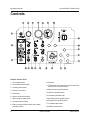
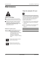
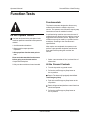
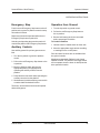
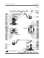
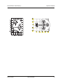
1
Before serial number Z30N-3448:
Incorrect operation can result from use of this manual on machines that have not been updated
according to Genie Campaign Bulletin 070001. Death or Serious Injury can result.
This manual only applies to machines that have been updated according to Genie Campaign
Bulletin 070001. Contact Genie Industries for information on this bulletin.
After serial number Z30N-3447:
Genie Campaign Bulletin 070001 does not apply to these machines.
Operator’s Manual
with Maintenance Information
Second Edition
Ninth Printing
Part No. 43651
Operator's Manual
Second Edition • Ninth Printing
Important
Read, understand and obey these safety rules and
operating instructions before operating this machine.
Only trained and authorized personnel shall be
permitted to operate this machine. This manual should
be considered a permanent part of your machine and
should remain with the machine at all times. If you
have any questions, call Genie Industries.
Contents
Page
Safety ........................................................................ 1
Controls ..................................................................... 8
Pre-operation Inspection ........................................... 10
Maintenance ............................................................. 12
Function Tests .......................................................... 14
Workplace Inspection ............................................... 19
Operating Instructions .............................................. 20
Transport & Lifting Instructions ................................. 25
Decals ...................................................................... 28
Specifications ........................................................... 30
Copyright © 1995 by Genie Industries
Contact us:
First Edition:
Internet:http://www.genielift.com
e-mail: [email protected]
Fourth Printing, August 1996
Second Edition:Ninth Printing, June 2007
"Genie"and "Z" are registered trademarks of
Genie Industries in the USA and many other
countries.
These machines comply with
ANSI/SIA 92.5-1992.
Printed on recycled paper
Printed in U.S.A.
Genie Z-30/20N
Part No. 43651
Operator's Manual
Second Edition • Ninth Printing
Safety Rules
Danger
Failure to obey the instructions and
safety rules in this manual will
result in death or serious injury.
Do Not Operate Unless:
You learn and practice the principles of safe
machine operation contained in this operator's
manual.
1 Avoid hazardous situations.
Know and understand the safety rules before
going on to the next section.
2 Always perform a pre-operation inspection.
3 Always perform function tests prior to use.
4 Inspect the workplace.
5 Only use the machine as it was intended.
You read, understand and obey:
Manufacturer's instructions and safety
rules—safety and operator's manuals
and machine decals
employer's safety rules and worksite
regulations
applicable governmental regulations
You are properly trained to safely operate the
machine.
Part No. 43651
Genie Z-30/20N
1
Operator's Manual
Second Edition • Ninth Printing
SAFETY RULES
Electrocution Hazards
Tip-over Hazards
This machine is not electrically insulated and will
not provide protection from contact with or
proximity to electrical current.
Occupants and equipment shall not exceed the
maximum platform capacity.
Maximum platform capacity
500 lbs
227 kg
Maximum occupants
2
Maintain safe distances from electrical power lines
and apparatus in accordance with applicable
governmental regulations and the following chart.
Voltage
Phase to Phase
Minimum Safe
Approach Distance
Feet
Meters
0 to 300V
Avoid Contact
300V to 50KV
10
3.05
50KV to 200KV
15
4.60
200KV to 350KV
20
6.10
350KV to 500KV
25
7.62
500KV to 750KV
35
10.67
750KV to 1000KV
45
13.72
Allow for platform movement, electrical line sway
or sag and beware of strong or gusty winds.
Do not raise or extend the boom unless the
machine is on a firm, level surface.
Do not depend on the tilt alarm as a level indicator.
The tilt alarm sounds in the platform only when the
machine is on a severe slope.
If the tilt alarm sounds:
Do not extend, rotate or raise the boom above
horizontal. Move the machine to a firm, level
surface before raising the platform. If the tilt alarm
sounds when the platform is raised, use extreme
caution to retract the boom and lower the platform.
Do not rotate the boom while lowering. Move the
machine to a firm, level surface before raising the
platform.
Do not alter or disable the limit switches.
Keep away from the machine if it contacts
energized power lines. Personnel on the ground or
in the platform must not touch or operate the
machine until energized power lines are shut off.
Do not operate the machine during lightning or
storms.
Do not use the machine as a ground for welding.
2
Genie Z-30/20N
Part No. 43651
Operator's Manual
Second Edition • Ninth Printing
SAFETY RULES
Do not drive over 0.6 mph / 1 km/h with the primary
boom raised or extended or the secondary boom
raised.
Do not use the platform controls to free a platform
that is caught, snagged or otherwise prevented
from normal motion by an adjacent structure. All
personnel must be removed from the platform
before attempting to free the platform using the
ground controls.
Do not operate the machine in strong or gusty
winds. Do not increase the surface area of the
platform or the load. Increasing the area exposed to
the wind will decrease machine stability.
Do not drive the machine on a slope that exceeds
the maximum uphill, downhill or side slope rating of
the machine. Slope rating applies to machines in
the stowed position.
Maximum slope rating, stowed position,
Counterweight uphill
20%
(11°)
Counterweight downhill
20%
(11°)
Side slope
20%
(11°)
Note: Slope rating is subject to ground conditions
and adequate traction.
Do not push off or pull
toward any object
outside of the platform.
Use extreme care and slow speeds while driving
Maximum allowable
side force - ANSI & CSA
150 lbs / 667 N
Maximum allowable
side force - CE
90 lbs / 400 N
the machine in stowed position across uneven
terrain, debris, unstable or slippery surfaces and
near holes and drop-offs.
Do not drive the machine on or near uneven terrain,
unstable surfaces or other hazardous conditions
with the boom raised or extended.
Part No. 43651
Do not alter or disable machine components that in
any way affect safety and stability.
Do not replace items critical to machine stability
with items of different weight or specification.
Do not modify or alter an aerial work platform.
Mounting attachments for holding tools or other
materials onto the platform, toeboards or guard rail
system can increase the weight in the platform and
the surface area of the platform or the load.
Genie Z-30/20N
3
Operator's Manual
Second Edition • Ninth Printing
SAFETY RULES
Do not place or attach overhanging loads to any
part of this machine.
Fall Hazards
Occupants must wear a
safety belt or harness and
comply with applicable
governmental regulations.
Attach lanyard to anchor
provided in platform.
Do not sit, stand or climb on the platform guard
rails. Maintain a firm footing on the platform floor at
all times.
Do not place ladders or scaffolds in the platform or
against any part of this machine.
Do not use the machine on a moving or mobile
surface or vehicle.
Be sure all tires are in good condition and lug nuts
are properly tightened.
Do not use batteries that weigh less than the
original equipment. Batteries are used as
counterweight and are critical to machine stability.
Each battery must weigh 105 pounds / 47.6 kg.
Each battery box including batteries must weigh a
minimum of 530 pounds / 240.4 kg.
Do not use the machine as a crane.
Do not climb down from the platform when raised.
Keep the platform floor clear of debris.
Lower the platform entry mid-rail or close the entry
gate before operating.
Do not push the machine or other objects with the
boom.
Do not contact adjacent structures with the boom.
Do not tie the boom or platform to adjacent
structures.
Do not place loads outside the platform perimeter.
4
Genie Z-30/20N
Part No. 43651
Operator's Manual
Second Edition • Ninth Printing
SAFETY RULES
Do not lower the boom unless the area below is
clear of personnel and obstructions.
Collision Hazards
Be aware of limited sight
distance and blind spots
when driving or operating.
Be aware of boom position when rotating the
turntable.
The machine must be on a level surface or secured
before releasing the brakes.
Do not drive the machine with the brakes released.
If the travel alarm sounds when not driving, the
brakes are released.
Check work area for overhead obstructions or other
possible hazards.
Limit travel speed according to the condition of the
ground surface, congestion, slope, location of
personnel, and any other factors which may cause
collision.
Use extreme care and slow speeds while driving
the machine in the stowed position on any slope.
Do not drive on a slope with boom raised.
Do not allow the machine speed on any slope to
exceed 3 mph / 4.8 km/h (walking pace).
Stop the machine by returning the drive control
handle to the center position or release the foot
switch.
Be aware of crushing hazards when grasping the
platform guard rail.
It is recommended that operators wear an approved
hard hat when operating the machine.
Observe and use the color-coded direction arrows
on the platform controls and drive chassis for drive
and steer functions.
Part No. 43651
When stopped on a slope, the machine may initially
move slightly downhill when the drive control handle
is moved to drive up the slope. Be sure the area
behind the machine is clear.
Do not drive on a slope with the wheels turned. Be
sure the wheels are aligned up and down the slope.
Genie Z-30/20N
Always use a winch to
load and unload a
machine from a
transport vehicle.
5
Operator's Manual
Second Edition • Ninth Printing
SAFETY RULES
Do not operate a boom in the path of any crane
unless the controls of the crane have been locked
out and/or precautions have been taken to prevent
any potential collision.
Decal Legend
Genie product decals use symbols, color coding
and signal words to identify the following:
No stunt driving or horseplay while operating a
machine.
Component Damage Hazard
Do not use the machine as a ground for welding.
Damaged Machine Hazards
Do not use a damaged or malfunctioning machine.
Conduct a thorough pre-operation inspection of the
machine and test all functions before each work
shift. Immediately tag and remove from service a
damaged or malfunctioning machine.
Be sure all maintenance has been performed as
specified in this manual and the
Genie Z-30/20N Service Manual.
Be sure all decals are in place and legible.
Be sure the operator’s, safety and responsibilities
manuals are complete, legible and in the storage
container located on the platform.
Bodily Injury Hazard
Do not operate the machine with a hydraulic oil or
air leak. An air leak or hydraulic leak can penetrate
and/or burn skin.
Safety alert symbol—used to alert
personnel to potential personal
injury hazards. Obey all safety
messages that follow this symbol
to avoid possible injury or death.
Red—used to indicate the
presence of an imminently
hazardous situation which, if not
avoided, will result in death or
serious injury.
Orange—used to indicate the
presence of a potentially
hazardous situation which, if not
avoided, could result in death or
serious injury.
Yellow with safety alert symbol—
used to indicate the presence of a
potentially hazardous situation
which, if not avoided, may cause
minor or moderate injury.
Yellow without safety alert
symbol—used to indicate the
presence of a potentially
hazardous situation which, if not
avoided, may result in property
damage.
Green—used to indicate operation
or maintenance information.
6
Genie Z-30/20N
Part No. 43651
Operator's Manual
Second Edition • Ninth Printing
SAFETY RULES
Battery Safety
Component Damage Hazards
Burn Hazards
Do not use any battery charger greater than 48V to
charge the batteries.
Batteries contain acid. Always wear protective
clothing and eyewear when working with batteries.
Both battery packs must be charged together.
Disconnect the battery pack plug before removing
the battery pack.
Electrocution Hazards
Connect the battery charger to a
grounded, AC 3-wire electrical
outlet only.
Inspect daily for damaged cord,
cables and wires. Replace
damaged items before
operating.
Avoid spilling or contacting battery acid. Neutralize
battery acid spills with baking soda and water.
The battery pack must remain in upright position.
Do not expose the batteries or the charger to water
or rain.
Avoid electrical shock from contact with battery
terminals. Remove all rings, watches and other
jewelry.
Explosion Hazards
Tip-over Hazard
Keep sparks, flames and
lighted tobacco away from
batteries. Batteries emit an
explosive gas.
The battery pack cover
must remain off during the
entire charging cycle.
Do not contact the battery terminals or the cable
clamps with tools that may cause sparks.
Part No. 43651
Do not use batteries that weigh less than the
original equipment. Batteries are used as
counterweight and are critical to machine stability.
Each battery must weigh 105 pounds / 47.6 kg.
Each battery box including batteries must weigh a
minimum of 530 pounds / 240.4 kg.
Lifting Hazard
Use a forklift to remove or install the battery packs.
Genie Z-30/20N
7
Operator's Manual
Second Edition • Ninth Printing
Controls
Platform Control Panel
1 Drive enable switch
10 Not used
2 Drive enable indicator light
11 Proportional control handle for drive function and
thumb rocker for steer function
3 Auxiliary power switch
12 Boom function speed controller
4 Platform level switch
13 Jib boom up/down switch
5 Horn button
14 Low battery indicator light
6 Boom extend/retract switch
15 Secondary boom up/down switch
7 Red Emergency Stop button
16 Primary boom up/down switch
8 Jib rotate switch (option)
9 Battery charge indicator and/or low voltage
interrupt (option)
8
17 Turntable rotate switch
18 Platform rotate switch
Genie Z-30/20N
Part No. 43651
Operator's Manual
Second Edition • Ninth Printing
CONTROLS
Ground Control Panel
1
2
3
4
5
6
7
Turntable rotate switch
Platform rotate switch
Platform level switch
Boom extend/retract switch
Auxiliary power switch
Hour meter
Key switch for platform/off/ground selection
Part No. 43651
8 Red Emergency Stop button
9 10A breaker for electrical circuits
10 Remote brake release
11 Jib rotate switch (option)
12 Jib boom up/down switch
13 Secondary boom up/down switch
14 Function enable switch
15 Primary boom up/down switch
Genie Z-30/20N
9
Operator's Manual
Second Edition • Ninth Printing
Pre-operation Inspection
Fundamentals
It is the responsibility of the operator to perform a
pre-operation inspection and routine maintenance.
Do Not Operate Unless:
You learn and practice the principles of safe
machine operation contained in this operator's
manual.
1 Avoid hazardous situations.
2 Always perform a pre-operation
inspection.
The pre-operation inspection is a visual inspection
performed by the operator prior to each work shift.
The inspection is designed to discover if anything
is apparently wrong with a machine before the
operator performs the function tests.
The pre-operation inspection also serves to
determine if routine maintenance procedures are
required. Only routine maintenance items
specified in this manual may be performed by the
operator.
Refer to the list on the next page and check each
of the items and locations for modifications,
damage or loose or missing parts.
Know and understand the pre-operation
inspection before going on to the next
section.
3 Always perform function tests prior to use.
4 Inspect the workplace.
5 Only use the machine as it was intended.
A damaged or modified machine must never be
used. If damage or any variation from factory
delivered condition is discovered, the machine
must be tagged and removed from service.
Repairs to the machine may only be made by a
qualified service technician, according to the
manufacturer's specifications. After repairs are
completed, the operator must perform a
pre-operation inspection again before going on to
the function tests.
Scheduled maintenance inspections shall be
performed by qualified service technicians,
according to the manufacturer's specifications and
the requirements listed in the responsibilities
manual.
10
Genie Z-30/20N
Part No. 43651
Operator's Manual
Second Edition • Ninth Printing
PRE-OPERATION INSPECTION
Pre-operation Inspection
! Be sure that the operator's, safety and
responsibilities manuals are complete, legible
and in the storage container located on the
platform.
! Be sure that all decals are legible and in place.
See Decals section.
! Check for hydraulic oil leaks and proper oil level.
Add oil if needed. See Maintenance section.
! Check for battery fluid leaks and proper fluid
level. Add distilled water if needed. See
Maintenance section.
Check the following components or areas for
damage, modifications and improperly installed or
missing parts:
Check entire machine for:
! Cracks in welds or structural components
! Dents or damage to machine
! Be sure that all structural and other critical
components are present and all associated
fasteners and pins are in place and properly
tightened.
! Be sure that both battery packs are in place,
latched and properly connected.
! After you complete your inspection, be sure that
all compartment covers are in place and
latched.
! Electrical components, wiring and electrical
cables
! Hydraulic power unit, reservoir, hoses,
fittings, cylinders and manifolds
! Drive and turntable motors and torque hubs
! Boom wear pads
! Tires and wheels
! Limit switches, alarms and horn
! Nuts, bolts and other fasteners
! Platform entry mid-rail/gate
! Beacon and alarms (if equipped)
Part No. 43651
Genie Z-30/20N
11
Operator's Manual
Second Edition • Ninth Printing
Maintenance
Check the Hydraulic Oil Level
Observe and Obey:
Only routine maintenance items specified in
this manual shall be performed by the operator.
Scheduled maintenance inspections shall be
completed by qualified service technicians,
according to the manufacturer's specifications
and the requirements specified in the
responsibilities manual.
Maintaining the hydraulic oil at the proper level is
essential to machine operation. Improper hydraulic
oil levels can damage hydraulic components. Daily
checks allow the inspector to identify changes in
oil level that might indicate the presence of
hydraulic system problems.
1 Be sure that the boom is in the stowed position.
2 Visually inspect the reservoir on the hydraulic
power unit.
Result: The hydraulic oil level should be within
the FULL and ADD marks on the hydraulic
reservoir.
Hydraulic oil specifications
Maintenance Symbols Legend
The following symbols have been
used in this manual to help
communicate the intent of the
instructions. When one or more of
the symbols appear at the
beginning of a maintenance
procedure, it conveys the meaning
below.
Hydraulic oil type
Refer to machine decal
Indicates that tools will be required
to perform this procedure.
Indicates that new parts will be
required to perform this procedure.
12
Genie Z-30/20N
Part No. 43651
Operator's Manual
Second Edition • Ninth Printing
MAINTENANCE
Check the Batteries
Scheduled Maintenance
Proper battery condition is essential to good engine
performance and operational safety. Improper fluid
levels or damaged cables and connections can
result in engine component damage and hazardous
conditions.
Electrocution hazard. Contact with
hot or live circuits could result in
death or serious injury. Remove
all rings, watches and other
jewelry.
Maintenance performed quarterly, annually and
every two years must be completed by a person
trained and qualified to perform maintenance on this
machine according to the procedures found in the
service manual for this machine.
Machines that have been out of service for more
than three months must receive the quarterly
inspection before they are put back into service.
Bodily injury hazard. Batteries
contain acid. Avoid spilling or
contacting battery acid. Neutralize
battery acid spills with baking
soda and water.
Perform this test after fully
charging the batteries.
1 Put on protective clothing and eye wear.
2 Be sure that the battery cable connections are
tight and free of corrosion.
3 Remove the battery vent caps.
4 Check the battery acid level. If necessary,
replenish with distilled water to the bottom of the
battery fill tube. Do not overfill.
5 Install the vent caps.
Part No. 43651
Genie Z-30/20N
13
Operator's Manual
Second Edition • Ninth Printing
Function Tests
Fundamentals
The function tests are designed to discover any
malfunctions before the machine is put into
service. The operator must follow the step-by-step
instructions to test all machine functions.
Do Not Operate Unless:
You learn and practice the principles of safe
machine operation contained in this operator's
manual.
1 Avoid hazardous situations.
A malfunctioning machine must never be used. If
malfunctions are discovered, the machine must be
tagged and removed from service. Repairs to the
machine may only be made by a qualified service
technician, according to the manufacturer’s
specifications.
After repairs are completed, the operator must
preform a pre-operation inspection and function
tests again before putting the machine into
service.
2 Always perform a pre-operation
inspection.
3 Always perform function tests prior to
use.
Know and understand the function tests
before going on to the next section.
1 Select a test area that is firm, level and free of
obstruction.
4 Inspect the workplace.
5 Only use the machine as it was intended.
At the Ground Controls
2 Turn the key switch to ground control.
3 Pull out the red Emergency Stop button to
the on position.
Result: The beacon (if equipped) should flash.
Test Emergency Stop
4 Push in the red Emergency Stop button to the
off position.
Result: All ground and platform control functions
should not operate.
5 Pull out the red Emergency Stop button to
the on position.
14
Genie Z-30/20N
Part No. 43651
Operator's Manual
Second Edition • Ninth Printing
FUNCTION TESTS
Test the Boom Functions
Test Auxiliary Controls
6 Do not hold the function enable switch to either
side. Attempt to activate each boom and
platform function toggle switch.
11 Turn the key switch to ground control.
Result: All boom and platform functions should
not operate.
7 Hold the function enable switch to either side
and activate each boom and platform function
toggle switch.
Result: All boom and platform functions should
operate through a full cycle. The descent alarm
(if equipped) should sound while the boom is
lowering.
Machines equipped with Platform Level Control
Disable Function: The platform level toggle switch
will not operate when the primary boom is raised
past the drive speed limit switch.
Test the Tilt Sensor
8 Pull out the platform red Emergency Stop
button to the on position. Turn the key switch to
platform control.
12 Simultaneously hold the auxiliary power switch
on and activate each boom function toggle
switch.
Note: To conserve battery power, test each
function through a partial cycle.
Result: All boom functions should operate.
13 Turn the key switch to platform control.
At the Platform Controls
Test Emergency Stop
14 Push in the platform red Emergency Stop button
to the off position.
Result: All platform control functions should not
operate.
Test the Horn
15 Pull out the red Emergency Stop button to the
on position.
9 Open the ground control side turntable cover
and locate the tilt sensor next to the function
manifold.
16 Push the horn button.
10 Press down one side of the tilt
sensor.
Test the Foot Switch
Result: The alarm, located in the
platform, should sound.
Result: The horn should sound.
17 Do not press down the foot switch. Activate
each machine function.
Result: The machine functions should not
operate.
Part No. 43651
Genie Z-30/20N
15
Operator's Manual
Second Edition • Ninth Printing
FUNCTION TESTS
Test Machine Functions
Test Drive and Braking
18 Move the lift/drive select switch to the lift
position (if equipped).
25 Move the lift/drive select switch to the drive
position (if equipped).
19 Press down the foot switch.
26 Press down the foot switch.
20 Activate each machine function toggle switch.
27 Slowly move the drive control handle in the
direction indicated by the blue arrow on the
control panel until the machine begins to move,
then return the handle to the center position.
Result: All boom/platform functions should
operate through a full cycle.
Note: Control the speed of boom functions by
adjusting the boom function speed controller.
Drive and steer functions are not affected by the
boom function speed controller.
Machines equipped with Platform Level Control
Disable Function: The platform level toggle switch
will not operate when the primary boom is raised
past the drive speed limit switch.
Test the Steering
21 Move the lift/drive select switch to the drive
position (if equipped).
22 Press down the foot switch.
28 Slowly move the drive control handle in the
direction indicated by the yellow arrow on the
control panel until the machine begins to move,
then return the handle to the center position.
Result: The travel alarm should sound. The
machine should move in the direction that the
yellow arrow points on the drive chassis, then
come to an abrupt stop.
Test Limited Drive Speed
23 Depress the thumb rocker switch on top of the
drive control handle in the direction identified
by the blue triangle on the control panel.
Result: The steer wheels should turn in the
direction that the blue triangles point on the
drive chassis.
24 Depress the thumb rocker switch in the direction
identified by the yellow triangle on the control
panel.
Result: The steer wheels should turn in the
direction that the yellow triangles point on the
drive chassis.
16
Result: The travel alarm should sound. The
machine should move in the direction that the
blue arrow points on the drive chassis, then
come to an abrupt stop.
29 Move the lift/drive select switch to the lift
position (if equipped).
30 Press down the foot switch.
31 Raise the primary boom 1 foot / 30 cm.
32 Move the lift/drive select switch to the drive
position (if equipped).
33 Slowly move the drive control handle to the full
drive position.
Result: The maximum achievable drive speed
with the primary boom raised should not
exceed 1 foot / 30 cm per second.
Genie Z-30/20N
Part No. 43651
Operator's Manual
Second Edition • Ninth Printing
FUNCTION TESTS
34 Move the lift/drive select switch to the lift
position (if equipped).
Test the Drive Enable System
44 Move the lift/drive select switch to the lift
position (if equipped).
35 Lower the boom to the stowed position.
36 Raise the secondary boom 1 foot / 30 cm.
37 Move the lift/drive select switch to the drive
position (if equipped).
38 Slowly move the drive control handle to the full
drive position.
Result: The maximum achievable drive speed
with the secondary boom raised should not
exceed 1 foot / 30 cm per second.
39 Move the lift/drive select switch to the lift
position (if equipped).
45 Press down the foot switch and retract the
primary boom to the stowed position.
46 Rotate the turntable until the boom moves past
one of the non-steer wheels.
Result: The drive enable
indicator light should come
on and remain on while the
boom is anywhere in the
range shown.
47 Move the drive control handle off center.
40 Lower the boom to the stowed position.
Result: The drive function should not operate.
41 Extend the primary boom 1 foot / 30 cm.
42 Move the lift/drive select switch to the drive
position (if equipped).
43 Slowly move the drive control handle to the full
drive position.
Result: The maximum achievable drive speed
with the primary boom extended should not
exceed 1 foot / 30 cm per second.
If the drive speed with the primary boom raised or
extended or the secondary boom raised exceeds
1 foot / 30 cm per second, immediately tag and
remove the machine from service.
48 Hold the drive enable toggle switch up or down
and slowly move the drive control handle off
center.
Result: The drive function should operate.
Blue
Note: When the drive enable system is in use, the
machine may drive in the opposite direction that the
drive and steer control handle is moved.
Use the color-coded direction
arrows on the platform
controls and the drive chassis
to identify the direction of
travel.
Yellow
Part No. 43651
Genie Z-30/20N
17
Operator's Manual
Second Edition • Ninth Printing
FUNCTION TESTS
Test Auxiliary Controls
Test the Lift/Drive Select Function
(CE models)
49 Move the lift/drive select switch to the
appropriate position (if equipped).
Machines with lift/drive select switch:
50 Press down the foot switch.
51 Simultaneously hold the auxiliary power switch
on and activate each function control handle or
toggle switch.
Note: To conserve battery power, test each
function through a partial cycle.
Result: All boom, steer and drive functions
should operate.
52 Move the lift/drive select switch to the lift
position.
53 Press down the foot switch.
54 Move the drive control handle off center.
Result: No drive functions should operate.
55 Activate each boom function toggle switch.
Result: All boom functions should operate.
56 Move the lift/drive select switch to the drive
position.
57 Press down the foot switch.
58 Activate each boom function toggle switch.
Result: No boom functions should operate.
59 Move the drive control handle off center.
Result: The drive functions should operate.
Machines without lift/drive select switch:
60 Press down the foot switch.
61 Move the drive control handle off center and
activate a boom function toggle switch.
Result: No boom functions should operate. The
machine will move in the direction indicated on
the control panel.
18
Genie Z-30/20N
Part No. 43651
Operator's Manual
Second Edition • Ninth Printing
Workplace Inspection
Workplace Inspection
Be aware of and avoid the following hazardous
situations:
Do Not Operate Unless:
You learn and practice the principles of safe
machine operation contained in this operator's
manual.
·
drop-offs or holes
·
bumps, floor obstructions or debris
·
overhead obstructions and high voltage
conductors
·
hazardous locations
·
inadequate surface support to withstand all
load forces imposed by the machine
·
wind and weather conditions
·
the presence of unauthorized personnel
·
other possible unsafe conditions
·
Determine the slope of any surface in the path
of travel on the job site
1 Avoid hazardous situations.
2 Always perform a pre-operation
inspection.
3 Always perform function tests prior to use.
4 Inspect the workplace.
Know and understand the workplace
inspection before going on to the next
section.
5 Only use the machine as it was intended.
Fundamentals
The workplace inspection helps the operator
determine if the work place is suitable for safe
machine operation. It should be performed by the
operator prior to moving the machine to the
workplace.
It is the operator's responsibility to read and
remember the workplace hazards, then watch for
and avoid them while moving, setting up and
operating the machine.
Part No. 43651
Genie Z-30/20N
19
Operator's Manual
Second Edition • Ninth Printing
Operating Instructions
Fundamentals
The Operating Instructions section provides
instructions for each aspect of machine operation.
It is the operator's responsibility to follow all the
safety rules and instructions in the operator's,
safety and responsibilities manuals.
Do Not Operate Unless:
You learn and practice the principles of safe
machine operation contained in this operator's
manual.
1 Avoid hazardous situations.
2 Always perform a pre-operation
inspection.
3 Always perform function tests prior to use.
4 Inspect the workplace.
5 Only use the machine as it was intended.
20
Using the machine for anything other than lifting
personnel and tools to an aerial work site is unsafe
and dangerous.
Only trained and authorized personnel should be
permitted to operate a machine. If more than one
operator is expected to use a machine at different
times in the same work shift, they must all be
qualified operators and are all expected to follow all
safety rules and instructions in the operator's,
safety and responsibilities manuals. That means
every new operator should perform a pre-operation
inspection, function tests, and a workplace
inspection before using the machine.
Genie Z-30/20N
Part No. 43651
Operator's Manual
Second Edition • Ninth Printing
OPERATING INSTRUCTIONS
Emergency Stop
Operation from Ground
Push in the red Emergency Stop button to the off
position at the ground or platform controls to stop
all machine functions.
1 Turn the key switch to ground control.
Repair any function that operates when the red
Emergency Stop button is pushed in.
Selecting and operating the ground controls will
override the platform red Emergency Stop button.
2 Pull out the red Emergency Stop button to
the on position.
3 Be sure both battery packs are connected
before operating the machine.
To Position Platform
1 Hold the function enable switch to either side.
Auxiliary Controls
Use auxiliary power if the primary power source
fails.
1 Turn the key switch to ground or platform
control.
2 Pull out the red Emergency Stop button to the
on position.
3 Move the lift/drive select switch to the
appropriate position (if equipped) when
operating the auxiliary controls from the
platform.
2 Move the appropriate toggle switch according
to markings on the control panel.
Drive and steer functions are not available from
the ground controls.
Machines equipped with Platform Level Control
Disable Function: The platform level toggle switch
will not operate when the boom is raised past the
drive speed limit switch.
4 Press down the foot switch when operating the
auxiliary controls from the platform.
5 Simultaneously hold the auxiliary power switch
on and activate the desired function.
The boom, steer and drive functions will operate
with auxiliary power.
Part No. 43651
Genie Z-30/20N
21
Operator's Manual
Second Edition • Ninth Printing
OPERATING INSTRUCTIONS
Operation from Platform
To Drive
1 Turn the key switch to platform control.
1 Press down the foot switch.
2 Pull out both ground and platform red
Emergency Stop buttons to the on position.
2 Increase speed: Slowly move the drive control
handle off center.
3 Be sure that both battery packs are connected
before operating the machine.
Decrease speed: Slowly move the drive control
handle toward center.
To Position Platform
Stop: Return the drive control handle to center or
release the foot switch.
1 Move the lift/drive select switch to the lift
position (if equipped).
2 Set the boom function speed controller to the
desired speed.
Note: Drive and steer functions are not affected by
the boom function speed controller.
3 Press down the foot switch.
4 Move the appropriate toggle switch according to
the markings on the control panel.
Machines equipped with Platform Level Control
Disable Function: The platform level toggle switch
will not operate when the boom is raised past the
drive speed limit switch.
To Steer
Use the color-coded direction arrows on the
platform controls and the drive chassis to identify
the direction the machine will travel.
The travel alarm will sound when the drive controller
is moved off center.
Note: When the turntable is rotated so the boom is
past the non-steer tires, the machine may move in
the opposite direction that the drive and steer
controls are moved.
Machine travel speed is restricted when the booms
are raised or extended.
Battery condition will affect the ability of the
machine to climb a slope.
1 Press down the foot switch.
2 Turn the steer wheels with the thumb rocker
switch located on top of the drive control
handle.
Use the color-coded direction arrows on the
platform controls and the drive chassis to identify
the direction the wheels will turn.
22
Genie Z-30/20N
Part No. 43651
Operator's Manual
Second Edition • Ninth Printing
OPERATING INSTRUCTIONS
Driving on a slope
Determine the uphill, downhill and side slope ratings
for the machine and determine the slope grade.
Maximum slope rating,
counterweight uphill (gradeability):
20% (11°)
While holding the piece of wood level, measure the
vertical distance from the bottom of the piece of
wood to the ground.
Divide the tape measure distance (rise) by the
length of the piece of wood (run) and multiply by
100.
Example:
Maximum slope rating, counterweight
downhill: 20% (11°)
run
Maximum side slope rating:
20% (11°)
rise
Note: Slope rating is subject to ground conditions
and adequate traction. The term gradeability applies
to the counterweight uphill configuration only.
Piece of wood = 144 inches (3.6 m)
Run = 144 inches (3.6 m)
Be sure the boom is below horizontal and the
platform is between the non-steer tires.
Rise = 12 inches (0.3 m)
To determine the slope grade:
12 in ÷ 144 in = 0.083 x 100 = 8.3% grade
Measure the slope with a digital inclinometer OR
use the following procedure.
0.3 m ÷ 3.6 m = 0.083 x 100 = 8.3 % grade
You will need:
carpenter’s level
If the slope exceeds the maximum uphill, downhill
or side slope rating, then the machine must be
winched or transported up or down the slope. See
Transport and Lifting Instructions section.
straight piece of wood, at least 3 feet / 1 m long
tape measure
Lay the piece of wood on the slope.
At the downhill end, lay the level on the top edge of
the piece of wood and lift the end until the piece of
wood is level.
Part No. 43651
Genie Z-30/20N
23
Operator's Manual
Second Edition • Ninth Printing
OPERATING INSTRUCTIONS
Driving Up/Down Slopes
Driving down a slope
Drive/Brake Control Theory
Be sure the platform is fully lowered and the
platform is between the drive wheels. Be sure the
wheels are aligned up and down the slope.
Brakes release progressively as the drive control
handle is moved out of neutral in either direction.
Brakes apply progressively as the drive control
handle is moved toward the neutral position. If the
machine is on a slope, the progressive release/
application of the brakes combined with torque from
the drive motors allows you to control the speed of
the machine. For this reason, in some
circumstances it is more effective to drive down a
sloped surface by moving the drive control handle
in the uphill direction. This is called “plug braking.”
Apply these principles for driving on a slope by
following the instructions below.
Driving up a slope
Be sure the platform is fully lowered and the
platform is between the drive wheels. Be sure the
wheels are aligned up and down the slope.
1 Press down the foot switch.
2 Move the drive control handle firmly.
When stopped on a slope, the machine may initially
move slightly downhill when the drive control handle
is moved to drive up the slope. Be sure the area
behind the machine is clear.
1 Position the steer wheels on the downhill side of
the slope.
2 Press down the foot switch.
3 On steeper slopes, it may be more effective to
move the drive control handle in the uphill
direction (plug braking) in order to drive downhill.
For this reason, no matter what slope you are
on, always begin the process of driving downhill
by slowly moving the drive control handle in the
uphill direction. Use small movements of the
drive control handle to control the machine
speed.
If the machine moves uphill instead of downhill, the
slope is too small to use plug braking. Move the
drive control handle back to the neutral position to
apply the brakes and proceed as follows:
4 Slowly move the drive control handle downhill.
Use small movements of the drive control
handle to control the machine speed.
To stop the machine completely, return the drive
control handle to the center (neutral position). The
machine can also be stopped by removing your foot
from the foot switch or pushing in the red
Emergency Stop button.
If machine speed exceeds 3 mph / 4.8 km/h
(walking pace), immediately stop the machine.
24
Genie Z-30/20N
Part No. 43651
Operator's Manual
Second Edition • Ninth Printing
OPERATING INSTRUCTIONS
Drive Enable
After Each Use
Light on indicates that the boom has moved past
either non-steer wheel and the drive function has
been interrupted.
1 Select a safe parking location—firm level
surface, clear of obstruction and traffic.
To drive, hold the drive enable switch up or down
and slowly move the drive control handle off
center.
Be aware that the machine may move in the
opposite direction that the drive and steer controls
are moved.
Always use the color-coded direction arrows on
the platform controls and the drive chassis to
identify the direction the machine will travel.
2 Lower the boom to the stowed position.
3 Rotate the turntable so that the boom is between
the non-steer wheels.
4 Turn the key switch to the off position and
remove the key to secure from unauthorized
use.
5 Chock the wheels.
6 Charge the batteries.
Low Battery Indicator Light
Flashing light indicates battery power is low and
the batteries need to be charged. There is
adequate power left to lower the boom and move it
to a location where the batteries can be charged.
Light on indicates the batteries are fully discharged.
Stop using the boom and charge the batteries
immediately.
Note: Machines equipped with Low Voltage
Interrupt Option will lose primary and secondary
boom lift functions when batteries are fully
discharged.
Part No. 43651
Genie Z-30/20N
25
Operator's Manual
Second Edition • Ninth Printing
OPERATING INSTRUCTIONS
Dry Battery Filling and
Charging Instructions
1 Remove the battery vent caps and permanently
remove the plastic seal from the battery vent
openings.
Battery and Charger Instructions
2 Fill each cell with battery acid (electrolyte) until
the level is sufficient to cover the plates.
Observe and Obey:
Do not fill to maximum level until the battery
charge cycle is complete. Overfilling can cause the
battery acid to overflow during charging.
Neutralize battery acid spills with baking soda and
water.
Do not use an external charger or booster
battery.
Charge the battery in a well-ventilated area.
3 Install the battery vent caps.
Use proper AC input voltage for charging as
indicated on the charger.
4 Charge the battery.
Use only a Genie authorized battery and
charger.
5 Check the battery acid level when the charging
cycle is complete. Replenish with distilled water
to the bottom of the fill tube. Do not overfill.
To Charge Battery
1 Be sure the batteries are connected before
charging the batteries.
2 Open the battery compartment. The
compartment should remain open for the entire
charging cycle.
3 Remove the battery vent caps and check the
battery acid level. If necessary, add only
enough distilled water to cover the plates. Do
not overfill prior to the charge cycle.
4 Replace the battery vent caps.
5 Connect the battery charger to a grounded AC
circuit.
6 Turn the battery charger on.
7 The charger will indicate when the battery is
fully charged.
8 Check the battery acid level when the charging
cycle is complete. Replenish with distilled water
to the bottom of the fill tube. Do not overfill.
26
Genie Z-30/20N
Part No. 43651
Operator's Manual
Second Edition • Ninth Printing
Transport & Lifting Instructions
Free-wheel Configuration for
Winching
1 Chock the wheels to prevent the machine from
rolling.
Observe and Obey:
The transport vehicle must be parked on a level
surface.
2 Release the non-steer wheel brakes by turning
over the torque hub disconnect caps (see
below).
The transport vehicle must be secured to
prevent rolling while the machine is being
loaded.
Machines with remote brake switch:
Plug the switch into the adaptor at the ground
control box. Apply the remote brake release
switch while winching the machine.
Be sure the vehicle capacity, loading surfaces
and chains or straps are sufficient to withstand
the machine weight. See serial plate.
3 Be sure the winch line is properly secured to the
drive chassis tie points and the path is clear of
all obstructions.
The machine must be on a level surface or
secured before releasing the brakes.
Always use a winch
to load and unload a
machine from a
transport vehicle.
After the machine is loaded:
1 Chock the wheels to prevent the machine from
rolling.
2 Apply the non-steer wheel brakes by turning
over the torque hub disconnect caps (see
below).
Towing the Genie Z-30/20N is not recommended. If
the machine must be towed, do not exceed
2 mph / 3.2 km/h.
Disengage
Position
Engage
Position
Remote brake switch
Part No. 43651
Genie Z-30/20N
27
Operator's Manual
Second Edition • Ninth Printing
TRANSPORT & LIFTING INSTRUCTIONS
Securing to Truck or Trailer for
Transit
Always chock the machine wheels in preparation
for transport.
Turn the key switch to the off position and remove
the key before transporting.
Inspect the entire machine for loose or unsecured
items.
Securing the Platform
Make sure the jib and platform are in the stowed
position.
Place a block under the edge of the platform
beneath the platform entry.
Secure the platform with a nylon strap placed over
the platform mount near the platform rotator (see
below). Do not use excessive downward force when
securing the boom section.
Securing the Chassis
Use the tie points on the drive chassis for
anchoring down to the transport surface.
Use chains or straps of ample load capacity.
Use a minimum of 4 chains.
Adjust the rigging to prevent damage to the chains.
28
Genie Z-30/20N
Part No. 43651
Operator's Manual
Second Edition • Ninth Printing
TRANSPORT & LIFTING INSTRUCTIONS
Lifting Instructions
Fully lower and retract the boom. Fully lower the jib.
Remove all loose items on the machine.
Determine the center of gravity of your machine
using the table and the picture on this page.
Observe and Obey:
Attach the rigging only to the designated lifting
points on the machine. There are four lifting points
on the chassis.
Only qualified riggers should rig and lift the
machine.
Be sure the crane capacity, loading surfaces
and straps or lines are sufficient to withstand
the machine weight. See serial plate.
Part No. 43651
Adjust the rigging to prevent damage to the
machine and to keep the machine level.
X Axis
31.2 in
79.2 cm
Y Axis
34.3 in
87.2 cm
Genie Z-30/20N
29
Operator's Manual
Second Edition • Ninth Printing
Decals
Decal Inspection
Use the pictures on the next page to verify that all
decals are legible and in place.
Below is a numerical list with quantities and
descriptions.
Part No.
Decal Description
27564
Danger - Electrocution Hazard
28157
Part No.
Decal Description
2
37053
Arrow - Blue
1
Label - Dexron
1
37054
Arrow - Yellow
1
28161
Danger - Crushing Hazard
3
37055
Triangle- Blue
2
28164
Notice - Hazardous Materials
1
37056
Triangle - Yellow
2
28165
Notice - Foot Switch
1
38110
Label - Travel Alarm
1
28171
Label - No Smoking
2
38111
Warning - Brakes Release
1
28174
Power to Platform, 230V
2
38112
Caution - Collision Hazard
1
28175
Caution - Compartment Access
1
40434
Label - Lanyard Anchorage
2
28176
Notice - Missing Manuals
1
43036
Platform Control Panel
1
28177
Warning - Platform Rotate
2
43652
Ground Control Panel
1
28181
Warning - No Step or Ride
1
43653
Notice - Operating Instructions, Ground
1
28235
Power to Platform, 115V
2
43658
Power to Charger, 230V
1
28236
Warning - Failure To Read . . .
1
43663
Notice - Function Enable
1
28372
Caution - Component Damage
2
44980
Power to Charger, 115V
1
31060
Danger - Tip-over Hazard, Interlock
4
44981
Airline to Platform
2
31508
Notice - Power to Charger
1
44986
Notice - Max Manual Force, 90 lbs / 400 N 1
31785
Notice - Battery Charger Instructions
2
52968
Cosmetic - Genie Boom
1
31786
Notice - Battery Connection Diagram
2
62928
Cosmetic - Genie Z-30/20N
1
31787
Danger - Tip-over, Batteries
2
62929
Cosmetic - Genie Z-30/20N
2
31788
Danger - Battery/Charger Safety
2
65171
Label - Circuit Breaker & Status Light
1
32700
Danger - Safety Rules
1
72080
Ground Control Panel
1
33952
Danger - Tilt-Alarm
1
72081
Platform Control Panel
1
35542
Notice - Lug Nuts
4
72167
Cosmetic - Genie Z-30/20N RJ
1
35583
Platform Control Panel
1
72833
Label - Open
2
37051
Notice - Max Side Force, 150 lbs / 667 N
1
82336
Label - Chevron Rykon
1
37052
Notice - Maximum Load, 500 lbs / 227 kg 1
114330
Danger - Safety Rules
1
114333
Notice - Operating Instructions, Platform
1
30
Quantity
Genie Z-30/20N
Quantity
Part No. 43651
Operator's Manual
Second Edition • Ninth Printing
DECALS
Ground
Controls
Side
Chassis
Platform
Power
Unit
Side
Shading indicates decal is hidden
from view, i.e., under covers.
Part No. 43651
Genie Z-30/20N
31
Operator's Manual
Second Edition • Ninth Printing
Specifications
Height, working maximum Models without rotating jib
36 ft
11 m
Height, working maximum Models with rotating jib
35 ft 2 in
10.7 m
Height, platform maximum Models without rotating jib
30 ft
Height, platform maximum Models with rotating jib
Maximum slope rating, stowed position,
Counterweight uphill
20%
(11°)
Counterweight downhill
20%
(11°)
9.1 m
Side slope
20%
(11°)
29 ft 2 in
8.8 m
Note: Slope rating is subject to ground conditions and
adequate traction.
6 ft 7 in
2m
21 ft
6.4 m
Width
3 ft 11 in
1.2 m
Length, stowed Models without rotating jib
16 ft 9 in
5.1 m
Length, stowed Models with rotating jib
17 ft 6 in
5.3 m
Height, stowed maximum
Horizontal reach maximum
Maximum load capacity
46 inch / 117 cm platform
227 kg
5 ft 2 in
1.6 m
Turning radius (outside)
9 ft 10 in
3.0 m
Turning radius (inside)
5 ft 5 in
1.7 m
Turntable rotation
Turntable tailswing
Power source
Controls
Platform dimensions,
(length x width)
359°
4 gallons
15 liters
Weight
See Serial Plate
(Machine weights vary with option configurations)
Airborne noise emissions
70 dB
Maximum sound level at normal operating workstations
(A-weighted)
Drive speed, stowed
0 - 3.3 mph
40 ft/8.2 sec
0 - 5.3 km/h
12.2 m/8.2 sec
Drive speed,
booms raised
or extended
0 - 0.6 mph
40 ft/40 sec
0 - 1.0 km/h
12.2 m/40 sec
Continuous improvement of our products is a
Genie policy. Product specifications are subject to
change without notice or obligation.
8 Group-L16,
6V 350AH Batteries
24V DC proportional
46 in x 30 in
1.17 m x 76 cm
self-leveling
Platform rotation
180°
Jib rotation (optional)
200°
AC outlet in platform
standard
Hydraulic pressure, maximum
(boom functions)
2800 psi
193 bar
32
8.9 cm
0°
Platform leveling
Tire size (solid rubber)
Hydraulic tank capacity
31/2 in
Drive speeds
500 lb
Wheelbase
Ground clearance
22 x 7 x 173/4 in
56 x 18 x 45 cm
Genie Z-30/20N
Part No. 43651
Operator's Manual
Second Edition • Ninth Printing
Part No. 43651
Genie Z-30/20N
33
Genie North America
Phone 425.881.1800
Toll Free USA and Canada
800.536.1800
Fax 425.883.3475
Genie Australia Pty Ltd.
Phone +61 7 3375 1660
Fax +61 7 3375 1002
Genie Scandinavia
Phone +46 31 575100
Fax +46 31 579020
Genie France
Phone +33 (0)2 37 26 09 99
Fax +33 (0)2 37 26 09 98
Genie Iberica
Phone +34 93 579 5042
Fax +34 93 579 5059
Genie Germany
Phone +49 (0)4202 88520
Fax +49 (0)4202 8852-20
Genie U.K.
Phone +44 (0)1476 584333
Fax +44 (0)1476 584334
Genie Mexico City
Phone +52 55 5666 5242
Fax +52 55 5666 3241
Genie China
Phone +86 21 53852570
Fax +86 21 53852569
Genie Malaysia
Phone +65 98 480 775
Fax +65 67 533 544
Genie Japan
Phone +81 3 3453 6082
Fax +81 3 3453 6083
Genie Korea
Phone +82 25 587 267
Fax +82 25 583 910
Genie Brasil
Phone +55 11 41 665 755
Fax +55 11 41 665 754
Genie Holland
Phone +31 183 581 102
Fax +31 183 581 566