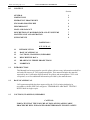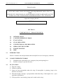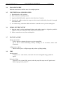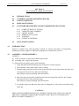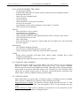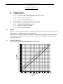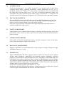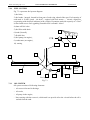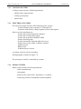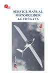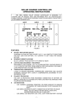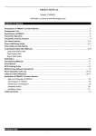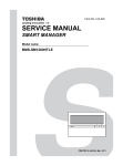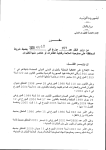
1
PILOT OPERATING HANDBOOK MOTORGLIDER J-6 FREGATA Translation made by inst. pilot Konrad Krychowski. All rights reserved. J&AS Aero Design Sp. z o.o. PILOT OPERATING HANDBOOK J-6 FREGATA PILOT OPERATING HANDBOOK MOTORGLIDER J-6 FREGATA C CL LA ASSSS O OFF A AIIR RC CR RA AFFT T ““SSPPE EC CIIA AL L”” THIS MOTORGLIDER CAN BE USED IN THE "SPECIAL" CATEGORY, ONLY FOR RECREATIONAL, SPORTS, NON-PROFIT PURPOSES AND OTHER NOT CORELATED WITH AIR TRANSPORTATION (THINGS OR PERSONS). NOBODY HAS RIGHTS TO USE THIS MOTORGLIDER FOR ISSUING A LICENSE OR THE ENTRY TO THE PILOT LICENSE. (NOT APPLICABLE TO FLIGHTS PERFORMED TO ACQUIRE SKILLS FOR THIS MOTORGLIDER) AND TO RENT IT BASED ON CONTRACT OR FOR THE MONEY. MOTORGLIDER MUST ONLY BE USED ACCORDING TO INFORMATION AND LIMITATIONS STATED IN THIS MANUAL. THIS MANUAL MUST ALWAYS BE ON BOARD. Manual was based on standards and procedures contained in AMC CS-22 1581 for gliders and motorgliders. No entries or supplements can be made in this manual without approval of adequate civil aviation authority. In case of loss this manual, immidiately inform adequate civil aviation authority, if outside the country – equivalent facility. Any person who find this manual is requested to send it to the adequate civil avaition authority. J&AS Aero Design Sp. z o.o. 0.3 PILOT OPERATING HANDBOOK J-6 FREGATA CONTENT Section GENERAL 1 LIMITATIONS 2 EMERGENCY PROCEDURES 3 STANDARD PROCEDURES 4 PERFORMANCE 5 MASS AND BALANCE 6 DESCRIPTION OF MOTORGLIDER AND ITS SYSTEMS 7 MAINTENANCE AND OPERATION 8 SUPPLEMENTS 9 ROZDZIAŁ 1 GENERAL 1.1 1.1 INTRODUCTION 1.2 BASE OF APPROVAL 1.3 CAUTIONS, WARNINGS, REMARKS 1.4 DESCRIPTIVE DATA 1.5 DRAWING IN THREE PROJECTIONS 1.6 MARKINGS INTRODUCTION This Manual has been prepared to provide pilots with neccesary information needed for safe and efficient use of J-6 Fregata motorglider. This manual includes the material required by the Certification Specifications for gliders and motorgliders CS-22 with exceptions, as well as additional information provided by the manufacturer. 1.2 BASE OF APPROVAL J-6 Fregata motorglider has been approved by the Civil Aviation Authority in accordance with the SPECIAL categories: TEMPORARY AIRCRAFT TESTING RULES built in single copies. 1.3 CAUTIONS, WARNINGS, REMARKS CAUTION: INDICATES THAT THE FAILURE OF FOLLOWING APPLICABLE PROCEDURE WILL ENDANGER OR DETERIORATE FLIGHT SAFETY. J&AS Aero Design Sp. z o.o. PILOT OPERATING HANDBOOK J-6 FREGATA WARNING: INDICATES THAT THE FAILURE OF FOLLOWING PROCEDURE LEADS TO MINOR OR LONG-TERM MORE OR LESS FLIGHT SAFETY DETERIORATION. REMARK: Draws attention to detail not related directly to the safety of the flight, but important or unusual. 1.4 DESCRIPTIVE DATA DESCRIPTION J-6 FREGATA is a single seat motor glider, made of glass-epoxy composites and designed for touristic flights and maintaining skills. Cantilever construction with V-tail. Fixed landing gear with tail wheel. The power unit is a pushing one. Bicipital aerofoil. Rectangular-trapezoidal shape of the wings. Each wing has aerodynamic brake that is extended from upper surface. Internal fuel tanks are mounted inside every wing. One-piece canopy that is opened aside and fitted with emergency droping system. Fixed rudder mounting, adjustable pilot seat and vetilation of the cabin. Control stick is on right side of the cabin. Control system for ailerons, elevator and aerodynamic brakes – by pushrods. Engine AEROHONDA BF 50D with brake power of 37.5 kW at 6000 rpm. Two blades, fixed propeller made of wood. Rotation is to the left-viewing behind. BASIC DATA: Wing span .................................................................................. 12,55 m Lenght ........................................................................................ 5,11 m High ............................................................................................ 1,58 m Lift area ...................................................................................... 9,13 m2 Aspect ratio ................................................................................ 17,25 Wing loading .............................................................................. 43,8 kG/m2 Main aerodynamic chord ........................................................... 0,762 m J&AS Aero Design Sp. z o.o. 1.5 PILOT OPERATING HANDBOOK DRAWING IN THREE PROJECTIONS: Motorglider J-6 FREGATA Fig. 1.1 J-6 FREGATA J&AS Aero Design Sp. z o.o. 1.6 PILOT OPERATING HANDBOOK J-6 FREGATA MARKINGS CAS – calibrated airspeed is the indicated airspeed corrected for instrument error and position error. CAS is equled to IAS in national standard atmosphere conditions at mean sea level. IAS - indicated airspeed of motorglider shown by its airspeed indicator in static-dynamic system, not corrected for velocity terror. In this manual instrument error has not been considered. HC – hull’s chord RC – main reference chord daN - dekanewton h - hour m - meter kg - kilogram mass. kG - kilogram force. km - kilometer s - second VS1 - stall velocity or minimum flight speed in given configuration. SECTION 2 LIMITATIONS 2.1 INTRODUCTION 2.2 VELOCITIES 2.3 AIRSPEED INDICATOR MARKINGS 2.4 POWER UNIT, FULE, OIL AND COOLING LIQUID 2.5 MARKINGS FOR POWER UNIT INSTRUMENTS 2.6 WEIGHT 2.7 CENTER OF GRAVITY 2.8 APPROVED MANEUVERS 2.9 COEFFICIENTS OF LOAD FACTOR DURING MANEUVERS 2.10 APPROVED CREW 2.11 APPROVED TYPES OF FLIGHT 2.12 MINIMUM EQUIPMENT 2.13 OTHER LIMITATIONS 2.14 PLACARDS AND MARKINGS J&AS Aero Design Sp. z o.o. 2.1 J-6 FREGATA PILOT OPERATING HANDBOOK INTRODUCTION Section 2 contains limitations, markings of instruments and placards necessary for and safe operation of motorglider, its instruments and equipment. Limitations included in section 9 have been approved by Polish Avaition Authority. 2.2 VELOCITIES: Limitations of velocity: Velocity 2.3 VNE Never exceeded km/h IAS 237 VRA Rough air 185 VA Maneuvering 185 Remarks Do not exceed in any case and do not deflect control surfaces abruptly Do not exceed in rough air as storms, gusts, up-draughts and down-draughts. Do not deflect control surfaces abruptly above given value. It may lead to overload. AIRSPEED INDICATOR MARKINGS Airspeed indicator markings are given below: Limitation Green arc IAS km/h 92 - 194 Yellow arc 194 - 237 Red line Blue line Yellow triangle 2.4 237 110 120 Meaning Normal operational range (1.1 VS1 to VRA) Maneuvers must be commenced with caution and in smooth air only. Never exceeded speed Best rate of climb speed VY Approach speed at maximum weight POWERPLANT, FUEL, OIL AND COOLING LIQUID: Engine Manufacturer : J & AS AERO DESIGN Type : AEROHONDA BF 50D Takeoff power : 37.5 kW (5 min) przy 6000 obr/min. Horsepower at MSL : 35.5 kW przy 5500 obr/min. Maximum temp. of cooling liq. : 120 °C (248 oF) Maximum oil temperature : 120 °C (248 oF) Oil quantity: maximum : 3,0 dm3 minimum : 2,0 dm3 Fuel – unleaded not less than 95 octane using in cars or AVGAS 100LL. J&AS Aero Design Sp. z o.o. J-6 FREGATA PILOT OPERATING HANDBOOK Oil – synthetic using in cars. OAT Specification according to SAE 5W50 0W50 above +5 °C below +5 °C Cooling liquid: automotive liquid for coolers based on glycol, according to specification of ASTM D3306 and ASTM D4985 (boiling temperature above 120oC) Drive line: engine is fitted with two transmissions one with gear-wheel greased by oil; gear ratio 1 : 1.269 and second with belt drive; gear ratio 1 : 1.67 Total gear ratio: 1 : 2.12 Maximum propeller routes – 2830 rpm at 6000 rpm given by the engine Propeller Manufacturer Type Diameter Pitch at 0.75 R Rotation 2.5 : J & AS AERO DESIGN : J6H : 1.25 m : 1.25 m : left viewing behind MARKINGS FOR POWER UNIT INSTRUMENTS Instrument tachometer [ rpm ] Oil temp. [°C ] Cooling temp. [°C ] Oil pressure [ kG/cm2 ] Fuel[ dm3 ] Red line Lower limit 40 (104 oF) Green arc Normal conditions Yelow arc Caution range Red line Upper limit 1000 - 5500 5500-6000 6000 40 - 120 120 (248 oF) 120 (248 oF) Green light means - correct pressure 0 Flashing light (red and green) means usable fuel left of 1,5 dm3. J&AS Aero Design Sp. z o.o. 2.6 PILOT OPERATING HANDBOOK J-6 FREGATA WEIGHT Maximum takeoff weight…..……………………………440 kG Maximum landing weight………...………………………440 kG Maximum weight of non-lifted parts……………………..267 kG Maximum baggage allowance..……………………………10 kG Maximum useful (crew, baggage, fuel)....………………..110 kG 2.7 CENTER OF GRAVITY Allowed range of C.G. in flight: forward 25 and rearward 41% MAC ( forward 0,23 and rearward 0,35 m from leading edge) Reference point – leading edge. CAUTION: MOTORGLIDER CAN BE USED SAFELY ONLY WHEN MASS AND BALANCE RESTRICTIONS DO NOT EXCEED GIVEN VALUES. 2.8 APPROVED MANEUVERS Motor glider is certified to perform: rapid nose up and down, deep turns, and static stall. 2.9 COEFFICIENTS OF LOAD FACTOR DURING MANEUVERS: Approved load factors: At VA = 185 km/h At VNE = 237 km/h 2.10 + 5.3, - 2.65 + 4.0, - 1.5 APPROVED CREW: Single-seat motor glider. Minimum crew – one pilot. 2.11 APPROVED TYPE OF FLIGHTS: Daily flight according to VFR. Motor glider can be used with or without mounted silencer. 2.12 MINIMUM EQUIPMENT: Airspeed indicator Altimeter Vertical Speed Indicator Compass Bank indicator Tachometer Fuel quantity gauge Oil temp. gauge Oil pressure gauge Cooling liquid temp. gauge Time meter of engine 1 p. 1 p. 1 p. 1 p. 1 p. 1 p. 1 p. 1 p. 1 p. 1 p. 1 p. J&AS Aero Design Sp. z o.o. 2.13 OTHER LIMITATIONS: 1) 2) 3) 4) 5) 2.14 PILOT OPERATING HANDBOOK Flights in knowing icing conditions are forbidden. VFR night flights are forbidden. Flights in clouds are forbidden. Intentional spins are forbidden. Acrobatics maneuvers are forbidden, except mentioned above. PLACARDS AND MARKINGS Baggage BAGGAGE MAX. 10 kG On fuel caps UNLEADED NOT LESS THAN 95 OCTANE USING IN CARS OR AVGAS 100LL On oil cap SF SG SAE 5W-50 Useable fuel (AT each indicator) Max. 37 dm3 Pressure in main wheels 0,2 +0.02 MPa Weight MOTORGLIDER J-6 FREGATA Max. weight in flight 440 kG Allowable weights in cabin Min. 60 kG Max. 100,1 kG Speed limitations and approved maneuvers placard MOTORGLIDER J-6 FREGATA Never exceeded VNE = 237 km/h Maneuvering VA = 194 km/h Approved aerobatic maneuvers: rapid nose up and down , deep turns, static stall J-6 FREGATA J&AS Aero Design Sp. z o.o. PILOT OPERATING HANDBOOK J-6 FREGATA Placard in cabin THIS AIRCRAFT RECEIVED PERMISSION TO CONDUCT FLIGHTS IN SPECIAL CATEGORY AND IT DOES NOT MEET THE REQUIREMENTS RELATING TO WIDE AND SPECIFIC PROVISIONS OF AIRWORTHINESS WHICH ARE BASED ON THE ANNEX 8 TO THE CONVENTION OF INTERNATIONAL CIVIL AVIATION Approved category placard SPECIAL SECTION 3 EMERGENCY PROCEDURES 3.1 3.1 INTRODUCTION 3.2 CANOPY EMERGENCY DROP 3.3 EVACUATION 3.4 STALL RECOVERY 3.5 UNINTENTIONAL SPIN RECOVERY 3.6 SPIRAL DIVE RECOVERY 3.7 ENGINE FAILURE 3.8 FIRE INTRODUCTION Section 3 contains lists and procedures that are helpful in case of emergency situations. 3.2. CANOPY EMERGENCY DROP 1) 2) 3.3. Simultaneously push both levers: emergency drop and opening lever. Push the canopy to upward direction. EVACUATION 1) Drop the canopy. 2) Unfasten seatbelts. 3) Jump out from motorglider under the wing (if motorglider is spinning, jump in the direction of rotation). 4) When the height is enough – open parachute with short delay, if the height is low – open parachute immediately. 5) If the propeller is not rotating, jump can be made on the wing. J&AS Aero Design Sp. z o.o. 3.4 PILOT OPERATING HANDBOOK J-6 FREGATA STALL RECOVERY Push the control stick, until the nose is in straight position. 3.5 UNINTENTIONAL SPIN RECOVERY 1) Retard throttle to idle position. 2) Place ailerons in neutral position. 3) Apply and hold full rudder opposite to the direction of rotation. 4) Just after the rudder reaches the stop, move the control stick briskly forward far enough to break the stall. 5) As rotation stops, neutralize rudder and make a smooth recovery from resulting dive. 3.6 SPIRAL DIVE RECOVERY 1) Stop the turn by using coordinated aileron and rudder control to align the symbolic airplane in the turn coordinator with the horizon reference line. 2) Make a smooth recovery from resulting dive 3.7 ENGINE FAILURE During takeoff roll: - before airborne: maintain direction, stop the motorglider - up to 100 m: land maintaining runway heading (to 30º deviation; rather with headwind). In flight above 100 m: - choose the best place in flight range and perform a gliding landing 3.8 FIRE On the ground: if engine is on – shut it down, close fuel valve and extinguish using ground fire agents. During the flight: close fuel valve, throttle fully opened, after the propeller stops turn off ignition and follow steps given in point 3.7. J&AS Aero Design Sp. z o.o. PILOT OPERATING HANDBOOK J-6 FREGATA SECTION 4 STANDARD PROCEDURES 4.1 INTRODUCTION 4.2 ASSEMBLY AND DISASSEMBLY PROCESS 4.3 DAILY INSPECTION 4.4 PRE-FLIGHT CHECK 4.5 STANDARD PROCEDURES AND RECOMMENDED VELOCITIES 4.5.1 START-UP, RUN-UP, TAXING 4.5.2 TAKEOFF AND CLIMBING 4.5.3 CRUISE FLIGHT 4.5.4 APPROACH TO LAND 4.5.5 LANDING 4.5.6 FLIGHT IN THE RAIN 4.6 4.1 POST-FLIGHT CHECK INTRODUCTION Section 4 contains lists and procedures needed for normal operations of motorglider. Standard procedures applies to additional equipment are contained in section 9. 4.2 ASSEMBLY AND DISASSEMBLY ASSEBLY A) Team: 3 persons (or 4 persons without special aids) B) Assembly aids : support for airframe C) Instruction of assembly step by step (montażu) : 1. clean and lubricate all the fittings, pins and joints of control systems. 2. place airframe on the suport aids, remove canopy 3. assemble right wing first: put tip of the spark into hull (do not forget about fuel line, fuel venting and electrical wire) and in the final stage enter fittings on pins protruding from the airframe 4. then left wing: put tip of the spark into hull (do not forget about fuel line, fuel venting and electrical wire) and in the final stage enter fittings on pins protruding from the airframe 5. set together spars tips and enter main pins in fittings hole, at the end secure them using safety pin CAUTION: PINS CAN BE ENTERED MANUALLY, WITHOUT USING ANY TOOLS. IN CASE OF FRICTION, ASSEMBLY SHOULD BE STOPPED AND CHECK IF THE PINS HAVE BEEN CLEANED CORRECTLY. J&AS Aero Design Sp. z o.o. PILOT OPERATING HANDBOOK J-6 FREGATA 6. Connect and protect the aileron control systems and aerodynamic brakes in the hull, 7. Connect the fuel lines, fuel venting and electrical fuel gauges, 8. V-tail wing set up the appropriate slot in the back of the hull, and insert the bottom of the hull two threaded bolts, 9. From the top to set up the bolts and washers and tighten the nuts and secure cotter or pin, 10. Screw the brackets to the right axis hinge tail control surfaces and then secure the wire, 11. Put the tip on the levers rudder pushrods, put on and tighten the nut and then protect them with safety pins, 12. After checking the correctness of the assembly to set up and secure with screws casing, 13. If the base used for mounting the hull - remove the motor-glider with bases, 14. Put on canopy and set up supply lines to connect to the system pressure flight instruments - check for leaks, D) DISASSEMBLY PROCESS: Disassembly takes place in the reverse order.. Bayonets’ pins of wings and screws of horizontal tail should be placed in appropriate holders, located on the main wheel cover inside the hull. 4.3 DAILY ISPECTION: Pre-flight check : 1) Check all the documents of motor glider. 2) Cockpit. - Chceck condition of the glass, open canopy - Chceck if pins of the wing are properly mounted and secured by safety pinss, - Set starter for first position and chceck engine gauges, fuel quantity and trimming włożyć kluczyk do stacyjki i przekręcić o jedną pozycję - Remove key from the starter - Check control surfaces for condition and free of movements - Chceck aerodynamic brakes for condition and free of movement - Chceck the cabin if there are no unwiling objects-remove - Chceck canopy for proper securing - Chceck seat belts - Chceck static and dynamic air sources 3) Landing gear. - Chceck condition and pressure in tyres - Chceck brake and shock absorbing - Chceck wheels for free of rotation - Chceck mounting of tail wheel and its control 4) Right wing. - Chceck surface, leading and trailing edge - Chceck if there are no unwiling clearances between wing and fuselage J&AS Aero Design Sp. z o.o. PILOT OPERATING HANDBOOK J-6 FREGATA - Chceck ailerons, deflections, friction, driving unit connects - Chceck aerodynamic brakes for condition - Chceck control unit of ailerons and brakes inside the cabin 5) Power unit. - Chceck oil quantity - Chceck quantity of cooling liquid - Chceck silencer for proper mounting and cracks - Chceck mounting of oil, cooling and fuel hoses - Chceck if there is no oil, fuel or cooling liquid leakage - Chceck propeller to crankshaft mounting and condition - Chceck systems to engine mounting - Check condition and tension of gear toothed belt, - Check condition and tension of V-belt that drives cooling liquid, - Chceck propeller surface and its cap - Chceck visualy fuel quantity in tanks 6) Control surfaces. - Check mounting, securing, surface condition, defelctions and frictions 7) Fuselage. - Check skin of the airframe if there are no cracks on painting, - Check inlet hole of oil cooler - Check drain valves for permeability 8) Left wing – as same as right wing. 4.5.2 TAKEOFF AND CLIMBING Before takeoff set trimmer for proper balance. The most efective way to commence takeoff as follows: pull control stick fuly pitch up and , open throttle, maintain direction by ruder and wait until 80km\h for rotation. Immediately after airborne push the control stick to accelerate and when speed is 105-110 km\h (Vy) start climbing. When 300ft AGL is reached, reduce power to 5500 rpm. Pilots with greater experience may climb with Vx which is 90km/h for shorter ground rolling. 4.5.3 CRUISE FLIGHT Motor glider has very good nature of flying in range of minimum speed to 180km.h. Above speed of 120km/h forces needed to control ailerons are enough. Engine shut-down in flight: Close throttle, oil temp. should decrease below 90 °C. Then reduce speed to around 100 km/h. Turn off magnetos. Up to Vne the propeller does not rotate. Engine start-up in flight: Start-up should be performed as on the ground but do not forget to warm up liquids before setting full power. 4.5.4 APPROACH FOR LAND The best approach speed with full useful is 120 km/h. Approach can be performed as engine on as off. The proper descent angle can be achieved using throttle and/or aerodynamic brakes. 4.5.5 LANDING Touchdown should be performed at 80 km/h on main gear or on three points. Never touches down with fully aerodynamic brakes opened. Maintaining direction is not so hard, but be careful using rudder. J&AS Aero Design Sp. z o.o. J-6 FREGATA PILOT OPERATING HANDBOOK Using slips to decrease altitude without accelerating is not allowed due to low rudder effectiveness. 4.5.6 FLIGHT IN THE RAIN Flight in the rain does not influence on the motor glider. However during test it was demonstrated a little increase of stall speed and lower speed of level flight-propably because of higher drug. 4.4 PRE-FLIGHT CHECK Before each flight the pre-flight check must be completed according to below mentioned procedures: 1 2 3 4 8 5 7 6 1. check visualy static and dynamic sources and also pressure in tires, 2. open the canopy – check connections and security of aileron actuators and aerodynamic brakes, check security of bayonet pins connecting the wing 3. check skin of left wing and closing of fuel cap, 4. check condition and mounting of aileron, 5. check for oil and cooling liquid leakages, visualy check condition of propeller and silencer mounting, 6. check mounting of V-tail – clearances and security of pins’ nuts, 7. check condition and mounting of aileron, 8. check skin of right wing and closing of fuel cap. 4.5 STANDARD PROCEDURES AND RECOMMENDED VELOCITIES 4.5.1 START-UP, RUN-UP, TAXING 4.5.1a BEFORE ENTERING THE CABIN - motorglider is equipped with two types of seatback: 1) for flights without parachute 2) for flights with parachute – choose the correct seatback whether or not using parachute. - adjust seatback in proper position. - check and wear parachute (if using it), J&AS Aero Design Sp. z o.o. PILOT OPERATING HANDBOOK J-6 FREGATA 4.5.1b AFTER ENTERING THE CABIN - sit and fasten seatbelts, - perform fully deflections of control systems, open and close aerodynamic brakes checking if they block, - check two-way communication, - set the altimeter, - close the canopy, - check throttle lever for proper movements, - insert key to the starter, - turn the battery master on by turning key to the right (1st position) - check fuel level (on indicators), Strat-up: - check if the fuel valve is opened, - open throttle for 1/5 distance, - check oil and cooling liquid temp., - rotate propeller around 10 times (ignition must be OFF), (it may be done earlier), - check if propeller area is clear - turn on the starter, - after start-up check oil pressure (if green light does not light up for 20 second shut down the engine), Warming up: - for 2 minutes maintain 1500 rpm, - next increase to 1500-2000 rpm up to oil temp. ≤40°C - run-up: maximum 5200 - 5400 rpm, check smooth of operation. Taxing: - during taxing especially with high speed, deflect rudder carefully due to high sensitivity of tail wheel, - at high speed taxing effectiveness of wheel brake is reduced. 4.5.2 TAKEOFF AND CLIMBING Before take-off set trimmer for proper balance. The most efective way to commence take-off as follows: pull control stick fuly pitch up and , open throttle, maintain direction by ruder and wait until 80kph for rotation. Immediately after airborne push the control stick to accelerate and when speed is 105-110 kph (Vy) start climbing. When 300ft AGL is reached, reduce power to 5500 rpm. Pilots with greater experience may climb with Vx which is 90kph for shorter ground rolling. 4.5.3 CRUISE FLIGHT Motor glider has very good nature of flying in range of minimum speed to 180kph. Above speed of 120kph forces needed to control ailerons are enough. Engine shut-down in flight: Close throttle, oil temp. should decrease below 90 °C. Then reduce speed to around 100 kph. Turn off magnetos. Up to Vne the propeller does not rotate. Engine start-up in flight: Start-up should be performed as on the ground but do not forget to warm up liquids before setting full power. J&AS Aero Design Sp. z o.o. PILOT OPERATING HANDBOOK J-6 FREGATA 4.5.4 APPROACH TO LAND Recommended approach speed with maximum weight equals 120 kph. Approach can be commenced with or without working engine. The proper descent angle can be achieved using throttle and/or aerodynamic brakes. 4.5.5 LANDING Touchdown should be made at around 84 kph on main wheels or on three points. Never touchdown with aerodynamic brakes fully opened. Maintaining direction is not difficult, but be careful when operating by tail wheel. Intentional slips for decreasing altitude without accelerating are not recommended due to low rudder effectiveness. 4.5.6 FLIGHT IN THE RAIN When flying in the rain no abnormal characteristics of airframe and engine occur. Only slight increasing of stall speed was observed simultaneously with straight flight speed decreasing.(which is caused by increasing drug on engine). 4.6 AFTER THE FLIGHT - Cool down engine below 90 °C and then shut it down - Check if there are no oil, fuel and cooling liquid leakage - Clean canopy glass J&AS Aero Design Sp. z o.o. PILOT OPERATING HANDBOOK J-6 FREGATA SECTION 5 PERFORMANCE 5.1 INTRODUCTION 5.2 APPROVED DATA 5.3 5.1 5.2.1 SCALING THE MEASUREMENT OF VELOCITY 5.2.2 STALL VELOCITY (IAS) 5.2.3 TAKEOFF PERFORMANCE FURTHER NOT APPROVED INFORMATION 5.3.1 CROSSWIND PERFORMANCE 5.3.2 POLAR CURVE OF SPPED 5.3.3 FUEL CONSUMPTION WSTĘP Section 5 contains approved data of scaling velocity measurement, stall speed, takeoff performance amd further not approved information. Given data were estimated based on actual test in flight with landing gear, maximum weight of 400 kg, engine in good condition and using average piloting techniques. The data will be verified in flight tests. APPROVED DATA: 5.2.1 SCALING THE MEASUREMENT OF VELOCITY 280 270 260 250 240 230 220 210 VCAS [km/h] 5.2 200 190 180 170 160 150 140 130 120 110 100 90 80 80 90 100 110 120 130 140 150 160 170 180 190 200 210 220 230 240 250 260 270 VIAS [km/h] Fig. 5.1. J&AS Aero Design Sp. z o.o. PILOT OPERATING HANDBOOK J-6 FREGATA 5.2.2 STALL VELOCITY (IAS) Motor glider has tendency to stall in straight flight smoothly with pilot and maximum weight. The lateral stability is maintained (as engine on as off). Flight with maximum pitch up control stick set is possible at 78-79 km/h. Motor glider with pilot and maximum weight stalls in turn with 45° bank very smoothly and it has tendency to increase bank towards the turn. It is possible to counteract this tendency by opposite deflection of ailerons. Stall speed increases to 83 km/h. When decreasing speed very slowly from 90 km/h with idle cut-off, you can pull control stick and should expect oscilation movement around 10-20º. When aerodynamic brakes are fully opened motor glider warns about approaching to stall. The stall speed in mentioned configuration takes place at 92 km/h in straight flight but in 45º bank at 95km/h. 5.2.3 TAKEOFF PERFORMANCE Takeoff lenght to reach 50 ft in ISA conditions and MTOM of 400kg as follows: Takeoff conditions concrete rwy grass rwy 5.3 Rolling [m] 220 300 Takeoff to 50ft [m] 340 450 FURTHER NOT APPROVED INFORMATION 5.3.1 CROSSWIND PERFORMANCE Maximum demonstrated crosswind during landing is 6 m/s 5.3.2 POLAR CURVE OF SPEED Characteristic points for polar curve: Range max VSmin = 23,5 at V=110 km/h, = 1,1 m/s at V=90 km/h . J&AS Aero Design Sp. z o.o. PILOT OPERATING HANDBOOK J-6 FREGATA Minimum descent velocity is less by 0.1 m/s than requirement in JAR 22. 5.3.3 FUEL CONSUMPTION J&AS Aero Design Sp. z o.o. PILOT OPERATING HANDBOOK MAXIMUM WEIGHT RANGE Maximum useful………………………………………..……110 kG Minimum weight of pilot with parachute.....................................60 kG Maximum weight of pilot with parachute…...............................110 kG J-6 FREGATA J&AS Aero Design Sp. z o.o. PILOT OPERATING HANDBOOK J-6 FREGATA SECTION 6 MASS AND BALANCE 6.1 INTORDUCTION 6.2 CENTER OF GRAVITY LIMITS AND APPROVED PAYLOAD 6.1 INTORDUCTION This section contains range of usable payload that allows to operate motorglider safely. Procedures of weighing and whole list of equipment for motorglider has been contained in Service Manual. 20.07.2012 Data Basic empty mass [cm] Data Approved Siganture CENTER OF GRAVITY LIMITS AND APPROVED PAYLOAD Center of gravity position 6.2 ALLOWABLE RANGE OF PAYLOAD Maximum payload (baggage in cabin + fuel)……………...……147,6 Minimum weight of pilot with parachute......................................60 Maximum weight of pilot with parachute.. ..............................110,1 kG kG kG J&AS Aero Design Sp. z o.o. PILOT OPERATING HANDBOOK J-6 FREGATA Position of the motorglider load relative to the reference: l.p. 1. 2. 3. 4. 5. Load Pilot without parachute Pilot with parachute Fuel Baggage Basic empty mass mpilot mpilot+parachute Mfuel mbaggage m0 position X [cm] Xpilot -46,7 Xpilot+ parachute -43,0 Xfuel 16,3 Xbaggage 27,0 X0 45-51 Formula for calculating C.G. position (for pilot without parachute and with normal seatback) Xsc = mo · Xo + mpilot · Xpilot + mfuel · Xfuel + mbaggage · Xbaggage / mo + mpilot + mfuel + mbaggage [cm] where: mfuel = fuel volume [dm3]*0,76 kG/dm3 Allowable range of C.G. must be within 21 cm - 35 cm according to reference. C.G. position for pilot with parachute can be calculated similarly. CAUTION Maximum forward load (21 cm according to reference): Pilot without parachute mass 100,1 kG Fuel mass 47,5 kG (62,5 dm3) Basic empty mass 292,4 kG (przy X0=45 cm) Total mass 440 kG Maximum rearward load (35 cm according to reference): Pilot without parachute mass 60 kG Fuel mass 0 kG (bez paliwa) Basic empty mass 292,4 kg (przy X0=51 cm) Total mass 352,4 kG AFTER FINISHING THE TESTS, MODEL FOR DETERMINATION OF C.G. AND WEIGHT,WILL BE REPLACED BY LOAD DIAGRAM J&AS Aero Design Sp. z o.o. PILOT OPERATING HANDBOOK J-6 FREGATA SECTION 7 DESCRIPTION OF MOTORGLIDER AND ITS SYSTEMS 7.1 7.1 INTRODUCTION 7.2 LEVERS IN COCKPIT 7.3 INSTRUMENTS 7.4 LANDING GEAR 7.5 SEAT AND SEATBELTS 7.6 STATIC AND DYNAMIC 7.7 AERODYNAMIC BRAKES 7.8 BAGGAGE COMPARTMENT 7.9 POWER UNIT 7.10 FUEL SYSTEM 7.11 OIL SYSTEM 7.12 COOLING SYSTEM 7.13 ELECTRICAL SYSTEM 7.14 RADIO SYSTEM INTRODUCTION This section contains description of motorglider and its systems. In case of needed information about additional equipment see section 9. Supplements. 7.2 LEVERS IN COCKPIT 1) throttle lever (full opened – full forward), 2) canopy lockers : - full forward - closed, - full aft - opened, 3) aerodynamic brake lever: - extending brakes – moving lever aft, - retracting brakes – moving lever forward, - locking brakes – press lever fully forward until feel noticeable breakdown - unlocking brakes – pull lever harder until feel noticeable breakdown 4) fuel valve (close-aft, open-forward), 6) brake lever (to brake - pull), 7) seat pillow, 8) 4-points seat belts, 9) emergency drop canopy lever – to drop canopy pull the lever maximum aft 10) control stick, 11) trimmer lever (full forward – nose down), J&AS Aero Design Sp. z o.o. J-6 FREGATA PILOT OPERATING HANDBOOK 12) seatback - adjustable. 13) ventilation lever – pull to open, 14) socket for headsets 10 0 4 14 6 8 12 7 9 2 3 4 7.3 INSTRUMENTS A) airspeed indicator PR250S, B) vertical speed indicator PR-03K, C) compass KI-13A D) turn coordinator EZS-4K, E) altimeter W12S, F) oil temp. gauge, J&AS Aero Design Sp. z o.o. J-6 FREGATA PILOT OPERATING HANDBOOK G) cooling liquid temp. gauge, H) rpm indicator of Honda, I) starter ( automotive type - using key) - first position to the right: battery and magnetos on; second position to the right: ignition J) fuel quantity gauge (dual), K) fuel reserve light (marked by letter R) - flashes red and green colour when fuel is 1,5l left L) oil pressure light – when green - correct M) radio, type MICROAIR M760 C H A M D B E K L I 6 F G 11 J Description of the instruments in the cockpit Fig. 7.2 J&AS Aero Design Sp. z o.o. 7.4 PILOT OPERATING HANDBOOK J-6 FREGATA LANDING GEAR Fixed main landing gear – two wheels mounted on two springs, made of glass-epoxy composite. Drum brake, controlled mechanicaly (cable). Dimensions are 350 x 135, pneumatic pressure 0.2+0.02MPa (2+0.2 atm.) (access to the delivery valve is possible from the cabin after removing wheel cover). Tail gear is amortized (composite spring) and controlled by the cables connected to the rudder. Angles of deflections +/- 20 degrees. Tail gear and wheels on the wings have dimensions 120 x 30 and do not have pneumatic systems. 7.5 SEATS AND SEATBELTS Pilot seat backrest can be removed from the cabin. Longitudinal adjustment is to place the lower hooks back in some the holes in the floor and the angle is adjusted by applying the palm rest on the front pipe fittings in several possible positions. Pilot used a four-point belts J5-00-00 have the range of adjustment that allows them to adjust the height and weight of pilots. 7.6 STATIC AND DYNAMIC Total pressure source is placed in the front part of fuselage and static pressure sources are placed in the sides. Access to remove water from the system is placed beneath instrument panel in cockpit. 7.7 AERODYNAMIC BRAKES Motor glider is fitted with aerodynamic brakes, extended form upper surface of the wings. Lever is placed inside the cockpit on the left side. 7.8 BAGGAGE COMPARTMENT Baggage compartment is located behind pilot seat in mid part of fuselage. Maximum weight of bagagge allowance is 10 kg. 7.9 POWER UNIT Engine AEROHONDA BF 50D is equipped with electronic fuel injection sytem, ignition advance angle adjustment, stabilization and automatic mixture adjustment. On-board diagnostic system monitors engine management sytem, indicating by lamp OBD faults, and by diagnostic fault codes to specify the sign, or a glass of OBD diagnostic tool with Honda. The engine is equipped mechanical and electrical fuel pump, alternator built into the flywheel, starter, driven coolant pump V-belt and belt drive reduces the speed of the propeller. Throttle control is done using the lever on the left side. Fixed pitch, two blades propeller with diameter of 1.25 m. Maintenance should be performed according to oryginal copy of Service Manual for Fregata J6 and for engine AEROHONDA BF 50D (doc. no AH/IOT/I/2012) J&AS Aero Design Sp. z o.o. 7.10 J-6 FREGATA PILOT OPERATING HANDBOOK FUEL SYSTEM Fig 7.3. represents fuel system diagram 1) fuel inlet, 2) fuel tanks - integral, located in front part of each wing, ahead of the spar. Fuel capacity of each tank is 30 dm3 (total - 60 dcm3)., equiped with fuel meters - - electric, capacitive, cooperating with dual fuel indicator in the cockpit. Expansion tank with capacity of 2.5 dm3 is fitted with reserve fuel sygnaling Unusable fuel is around 1.0 dm3 4) shutt-off fuel valve 5) fuel filter with drain 9 6) bend (firewall), 7) flexible line, 8) fuel pump (on engine), 9) carburators (on engine), 10) venting 10 8 7 7 1 1 2 TO THE FUEL PUMP 2 3 4 5 6 Fuel system. Fig 7.3. 7.11 OIL SYSTEM Oil system consists of following elements: oil reservoir located in fuselage, oil cooler, oil pump in the engine, - lines starting with the reservoir, which task is to provide oil to the circuit before the oil is sucked from the tank. J&AS Aero Design Sp. z o.o. 7.12 PILOT OPERATING HANDBOOK COOLING SYSTEM Cooling system consists of following elements: radiator with expansion tank, cooling system pump radiator hose 7.13 ELECTRICAL SYSTEM The electrical system consists of the following power sources: - Lead-acid battery with a capacity of 12Ah and 12V, - Alternator with built-in voltage regulator (built on the engine). Receivers with installations are: - Feeder and coolant temperature indicator - Feeder and oil temperature gauge, - Feeder and oil pressure indicator (LED) - Emitter and fuel gauge, - Feeder tank and the outgoing light fuel reserve, - Engine start circuit (starter, contactor, breaker) - Ignition circuit, - Radio aerial, - Additional power socket. A separate electrical circuit is bonding. Wiring diagram is shown in Figure 7.4. The main power switch is controlled by a starter. 7.14 RADIO SYSTEM Radio system consists of following elements: - radio communicaton - rod antenna, - button on the control stick ( transmision - reception) - connecting sockets for headphones and microphone J-6 FREGATA J&AS Aero Design Sp. z o.o. PILOT OPERATING HANDBOOK Electrical system. Fig. 7.4. J-6 FREGATA J&AS Aero Design Sp. z o.o. PILOT OPERATING HANDBOOK J-6 FREGATA SECTION 8 MAINTENANCE AND OPERATION 8.1 8.1 INTRODUCTION 8.2 PERIODIC INSPECTIONS 8.3 MODIFICATIONS AND REPAIRS OF MOTORGLIDER 8.4 GROUND HANDLING / ROAD TRANSPORT 8.5 CLEANING AND MAINTENANCE INTRODUCTION This section contains the procedures recommended by the manufacturer for proper ground handling and servicing of motorglider. It also sets out certain inspection and maintenance requirements that need to be done if the motorglider is to retain the performance and reliability of the new. Observe the planned schedule of lubrication and preventive maintenance based on the vagaries of flight conditions and climate. 8.2 PERIODIC INSPECTIONS Periodic inspections are contained in SERVICE MANUAL. 8.3 MODIFICATIONS AND REPAIRS OF MOTOR GLIDER It is necessary to contact the appropriate authority before making any changes in motor glider to ensure the airworthiness of the glider will not be affected. Before the concept of decision making any repairs refer to the entries in the Maintenance Manual. 8.4 GROUND HANDLING / ROAD TRANSPORT ROLLING MOTOR GLIDER Motor glider can be rolled by hand in accordance with generally accepted principles. During the long rolling canopy should be closed, and control stick should be secured.. CAUTION: Never push on the wing tips, empennage and control surfaces. PARKING During stop canopy should be closed and protected by cover. UWAGA: Never leave unsecured motor glider without supervision. SECURING ON THE GROUND - place the motor glider as wind blows from the tail and left or right one side, secure using wing tips, main landing gear and tail wheel strut spring, secure control stick J&AS Aero Design Sp. z o.o. PILOT OPERATING HANDBOOK J-6 FREGATA ROAD TRANSPORT In order to prepare motor glider for transport following points should be done: - chceck completeness of motor glider, - empty the cabin, - close windown and canopy, - cover the canopy, - secure tips of control unit sticking out from wings against unwanted movements, - secure ailerons and control surfaces, - fix motor glider on the trailer such way to prevent formation damage CAUTION: 1. Permeability of fuel tanks venting must be provided. 2. Motor glider transported using open trolley should be protetected by covers. 8.5 CLEANING AND MAINTENANCE CLEANING Motor glider should be washed with water and normal detergent using a sponge or soft cloth. Similar media should be used to clean the propeller. After cleaning, check the permeability of the drainage holes and, if necessary - dry interior of the structure (especially the brake boxes). The engine should be washed by any items intended for automotive engine or by kerosene. Glazing should be wiped with a soft cloth and the dull should be polished by polishing paste. The cockpit should be cleaned regularly with a vacuum cleaner. . UWAGA: Using organic solvents as petrol, nitro etc. to clean canopy is forbidden. IN THE HANGAR Motor glider should be stored in a dry and ventilated place. If longer storage takes place it is necessary to protect fittings from corrosion by grease. When storing disassembled motor glider, its systems should be placed in such a way that cannot created permanent deformation: - wings leading edge down side, supported on the leading edge, near to closing rib or supported by the bayonets, and at the end of the wings on a soft, fitted stand, - airframe the matching cover, and the back of the hull can plant a stand; -empennage – on the soft ground to the bottom of the leading edge CAUTION: After outside storage the inside of the structure should be chcecked if there is no water then cleaned and dried.