1
N9512 Rev.A 8/95
Downloaded from www.Manualslib.com manuals search engine
Quick Reference
TURN SYSTEM ON
Check to make sure the system is READY - Green ready light is lit
Enter your four digit user code
❑ unn
The On/Off (Arm) light will light
Exit through a door designated
by your installer as an exitientry door.
TURN SYSTEM OFF
Enter through a door designated
by your installer as an exiffenty
Enter your four digit user code
❑ oon
door,
The System On (Arm) light will go out
TURN SYSTEM ON AND STAY INSIDE
Check to make sure the system is READY - Green ready light is lit
~
Followed by your user code
❑ DDD
The On/Off (arm) fight and the Stay light will both light
REMEMBER: You must turn the system off if you want to open the door or
leave the premises after the exit time has passed,
TURN THE SYSTEM ON: PERIMETER
INSTANT MODE AND STAY INSIDE
~
H
SENSORS
Check to make sure the system is READY - Green readv light is tit
~
followed
by
followed by your user code
- -
❑❑ ❑ ❑
The On/Off light, the Instant light and the Stay light will all be on
SMOKE DETECTOR
RESET
Enter your four digit user code
❑❑❑❑
ALARM COMPANY SERVICE NUMBER
Downloaded from www.Manualslib.com manuals search engine
Introduction
Congratulations on your decision to protect your home or business wiih the
XL-2S security system. You have chosen a reliable, state of the afl se:urity
system that is remarkably
easy to operate. Your system hae been
professionally installed by your local Security Company who can explain
the specifics of your system.
The keypad is the input and display device for your security system. The
following keypad models can interact with your system. Your Security
Company will suggest the model most appropriate for your premises and
your needs.
XL-4600SM — A surface mount keypad containing indicator tights for each
of the 6 zones (areas of protection). The door coveting the buttons is
optional and can be removed.
6805 — Keypad with a plastic case and a two line English read-out LCD
(liquid crystal display). Status messages for the zones (areas of protection)
are displayed in simple English.
The XL-2S is listed by Undemriters
Burgla~ applications.
Laboratories
Throughout this manual the following conventions
keystrokes required to perform the functions.
~
:
❑
for Household
Rn? and
are used to display the
- Button labeled BYPASS
~
- Button labeled INSTANT
~
- Butte”
labeled STAY
1
- Button
labeled CODE
uun
- Four digit user code
Please keep your manual in a convenient
needed.
Downloaded from www.Manualslib.com manuals search engine
location so you can refer to it if
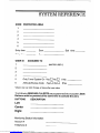
SYSTEM REFERENCE
ZONE
PROTECTED
AREA
1
2
3
4
5
6
Entry time
Door
Entry time
Door
ASSIGNED
USER ID
Exit
time
TO
1
(MASTER USER .)
2
3
4
5
Only Turns System On-Yesn
Non
If No
6
Ambush/Duress
Non
If No
Code
-Yesn
“Master User can Add, Change, or Erase other user codes.
The following SEND HELP ALERTS are programmed into my system. Both
Buttons must be pressed at the same time to activate the alert.
BUTTONS
DESCRIPTION
Leff
Center
Right
Monitoring
Station Information
Account #
Telephone
#
Downloaded from www.Manualslib.com manuals search engine
TU~ING
T~
SYSTEM ON
You can turn the Burglar portion of your security system on and off. Before
you turn the system on it must be ready, If you have a protected door c)pen,
or someone is moving by a motion detector the system will not show ready
syetem is ready if the ready light ie on or if the display shows:
The
~
TURN THE SYSTEM ON AND LEAVE
Enter your four digit user code
❑ oon
The System On (Arm) light will go on or the display will show
~
Exit through a door designated by your installer as an exiffent~ door. You
must leave within the period of time known as the exit time. Check the
reference sheet for the time that has been set for your system.
NOT READY
If the system is not ready to be armed the READY light will be off and the
Zone lights will show which zone or zones are not ready. The zone lights
indicate the following conditions or the display will show as below:
Fast Btink
Slow BlinWLow
Slow Pulse
Solid On
Alarm
Intensity
Bypass
Trouble
Not Ready
Exemple: If the Ready light is not lit and the zone one light is sofid on.
An alarm sensor on zone one is not normal. This might mean that a window
is open or someone is walking through a motion sensor. Check all sensors
on zone one and resolve the problem. When all sensors are normal the
Ready light will come on and the zone hght will go out.
~splay
shows:
~
~
TO TURN THE SYSTEM ON - NOT READY
Determine which zone or zones is not ready, resolve the problem and turn
the system on normally. If the problem cannot be resolved you may bypass
the zone that is not ready. Bypassing should only be done if the problem
on the zone cannot be resolved OR if you intentionally wish to leave the
Downloaded from www.Manualslib.com manuals search engine
zone off, Example: you wish to keep the window open for ventilation. Zones
that are bypassed are not protected whenthe systemison.See Bypass
for the correct procedure.
TURN SYSTEM ON AND STAY INSIDE
To turn the perimeter potion of your burglar alarm on and move around
freely inside is the STAY mode.
Check to make sure the system is READY
~
when ready press:
FO[lOwed by your user code
❑ oon
If successful the On/Off (arm) light will be lit and the Stay tight will also be
lit or the display shows:
ON: STAY
J
I
REMEMBER: You must turn the system off if you want to open the door or
leave the premises after the exit time has passed.
TURN THE SYSTEM ON: PERIMETER
INSTANT MODE AND STAY INSIDE
SENSORS
In INSTANT STAY mode the perimeter portion of your burglar alarm system
is on and the time delays are ehminated from your normal ent~/exit door(s).
All interior protection is off so you are free to move around inside.
Check to make sure the system is READY, when ready press:
~
followed by
B~
folfowed by your user code
❑❑ ❑ ❑
If successful the On/Off tight, the Instant light and the Stay fight will all be
on or the display shows:
~
BYPASS
Bypass excludes a zone of protection from the security system until it is
unbypasssed unless you have auto-bypassing enabled. Bypassing can only
be done while the syetem is turned off.
Press the Bypass Button followed by your user code and then the Zone #
(1-6) to be bypassed.
❑ ODD
,ONE
NOTE: Bypassed zones are not protected when the system is turned on.
After the bypass command has been accepted the keypad will sound one
Downloaded from www.Manualslib.com manuals search engine
long beep and the zone or zones bypassed will slowly blink or the display
shows:
~
NOTE: Temporary users (i.e. baby sittars, housekeepers,
be shown the Bypass procedure.
etc.) should not
UNBYPASS
Unbypasa returns a bypassed zone to normal operation.
Unbypass is a repeat of the bypass function,
After unbypassing
the zone display will show the state of the zones.
TURN THE SYSTEM OFF
When you turn off the system you turn off only the burglar portion of your
system, any smoke or heat detectors and panic buttons will ramain orl. You
must enter through a designated entry door and turn off the system within
the time allowed. You can have different amounts of time for different entry
points. See your system reference sheet for the times estabffshed for your
system.
Enter your four digit user code
❑ 000
[f no alarms have taken place, the On/Off light (labeled arm) will go off or
the display shows
~
If alarms occurred when the system was on, or if a trouble contition
they wifl display on the zone inficator fights as follows:
Fast Blink
Slow BfinWLow
exists
Alarm
Intensity
Bypass
Slow Pulse
Trouble
Solid On
Not Ready
or the dispfay shows:
~:
Burglary Alarms wilf sound a steady sound through the keypad(s) and fire
alarms will generate a pulsing sound.
Important
If an intrusion has taken place while you were away, do not enter
until the location has been checked. Call for help from a neighbots house
and wait for the potice.
Downloaded from www.Manualslib.com manuals search engine
After you have turned the system off with your user code the message on
display keypads will show
To clear the display of the alarm or trouble conditions and silence the audible
alert:
Enter your four digit user code
❑ UUD
again.
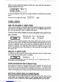
USER CODES
ADD OR CHANGE A USER CODE
Users can be entered or modified directly through the keypad. Your system
can have up to 6 different User Codes. User #1 is the Master User and is
the only one allowed to add, or delete other users.
Press the Code button followed by the four digit master user code then the
user # and the new four digit user code. The keypad will beep after each
digit is pressed.
MasterUser Code User ID New User Code
~
❑ 000
us
❑ nnn
There is a record sheet provided in the back of the book to help you plan
and record your users. On this sheet your installer will indcate if you have
chosen to dedicate a user code to send an emergency signal in the case of
Ambush or Duress. You may also have chosen to reserve one user code
that is only allowed to turn the system on, this code will not be able to turn
the system off.
DELETE A USER CODE
To delete user #3, press the code button followed by the four digit master
user code, then the user # then “ to delete.
MasterUser Code User ID -to delete
❑
oon
,
*
-[
NOTE User #1, the master user, cannot be deleted b“t it ca” be ~hanged “sing the AOD
OR CHANGE USER PROCEDURE.
TURN SYSTEM ON ONLY (Maid Code)
If you choose to have a code that cannot turn the system off, but can turn
the system on, have your installer program this feature. If programmed,
user code #5 will have System On capability only and you can issue this
code to a temporary user so they can secure the premises when they leave.
KEYPAD SE~
HELP CONDITIONS
Your system can be programmed for 3 separate Send Help Alerts which
would send an emergency signal to your central station, See System
Reference sheet to see wMch have been programmed for your system,
Downloaded from www.Manualslib.com manuals search engine
Duress
Your system can be programmed to send an emergency signal to the
Central Station if you are forced to enter the premises. If you choose to
include this feature, User Code number 6 is dedicated to this function and
must only be used under a duress circumstance.
❑
Quick On - (Quick Arming) Yes
❑
No
If programmed by your installer, QUICK ON, or Quick Arming allows you to
turn the system on to the away mode without user code. NOTE: Turning
your system Off always requires a valid User Code.
#1
Quick Forced On -
Yes
❑
No
❑
If programmed by your installer Quick Forced On, allows you to turn the
burglar portion of your alarm system on to the away mode bypassing all
zones that are not ready.
#2
NOTE: A valid user code is still required to turn the system off.
NOTE: This feature is disabled on UL installations.
Quick Bypass
Yes
❑
No
❑
If you have quick bypass programmed for your system you will not have to
use your user code to bypass zones. The quick bypass procedure is:
ml
ZONE
(,-6)
NOTE: Bypassed zones are not protected when the system is turned on.
After the bypass command has been accepted the keypad will sound one
long beep and the zone or zones bypassed will slowly blink or the display
will show
NOTE: Temporay users ~,e. baby sitters, housekeepers,
be shown the Bypass procedure.
etc.) should not
Turn Ckime OtiOff
Chime is an optional feature that causes the keypad to chima when selected
doors are opened when the burglary protection is off or disarmed.
Only your installer can program a zone for the chime feature, but once
programmed you can turn ctime on or off to meet your daily needs. To turn
Press
#6
chime on or off.
Downloaded from www.Manualslib.com manuals search engine
i@de
the ~miti.
I
E
Downloaded from www.Manualslib.com manuals search engine
COVER
{OPEM
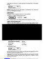
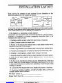
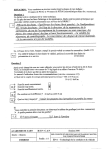
INSTWWTION
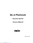
Eady warning fire detection is best achieved
detection equipment in the location as follows
,~)
WYOLJT
by the installation
ml
-.
v
““~”~
.—
~
I
I—-
of fire
.w!Id
lAlff—
I
In homes Mm more than one sleeping srea a smke detector should be provided to protect
each area. Smoke detectors shall be l-ted
bemeon the sleeping area and the rest of the
house. NOTE Referto N.F.P,A.874 Appendx BI.1 mmugh B-1O.
In the @agram a + represents a smoke detector.
Preparation of an evacuation plan is of prime importance in fire prevention.
Estabhsh a household or business emergency
evacuation plan to be
followed in the event of a fire.
1. Evaluate possible escape routes from your home or business.
2. Select 2 escape routes from each room.
3. Rooms on the second floor should have a rope ladder (make sure it
reaches the ground) or fire escape.
4. Draw a rough sketch of your escape plan so everyone is familiar with it.
5. Practice your escape plan to make sure everyone
knows what to do.
6. Establish a meeting place outside where everyone will meet.
7. Advise the local fire authority that you have installed a fire alarm system.
8. When the fire alarm signals, LEAVE IMMEDIATELY.
belongings.
Do not stop for
9. If a fire occurs, test the door. If hot, use your alternate route. If the door
is cool, brace your shoulder against it and open it cautiously. Shut the door
to help prevent the fire and smoke from spreating. Crawl through smoke
holding your breath.
10. Contact the Hre Department
from a neighboring
11. Everyone, including neighbors,
BurglaV audible alarm sounders.
fire Alarm
Sound
is:
Burglar Alarm Sound is:
Downloaded from www.Manualslib.com manuals search engine
house or business.
should be famifiar with your Fire and
SYSTEM LIMITATIONS
LIMITATIONS
OF THIS ALARM SYSTEM
While this system, is an advanced design secuflty system, it does not offer guaranteed
protetion againti burglay, fire, or other emergency. Any alarm system, whether mmmercial
or residential, is su~ect to compromise or failure to wam fora vatiefy of reasons. For example
B Intruders
=ptistiation
may gain access through unprotected openings or have the technical
to bypass an alarm sensor or disconnect an alarm warning device.
~ Intrusion detetiors (e.g. passive infrared detectors), smoke detectors, and many other
sensing devices will not work without batfeties, or if the batteries are not put in properly.
Devices powered solely by AC will not work if their AC power supply is cut off for my reason,
however btiefly.
@ Signals sent by wireless transmitters maybe blocked or reflected by metal before they reach
the slam receiver. Even if the signal path h= been recently checked dufing a weekly test,
blockage can occur if a metal objed is moved into the path.
Q A user may not be able to reach a panic or emergency button quickly enough.
O While smoke detetiors have played a key role in reducing residential fire deaths in the
United States, they may not activate or provide early warning for a vatiety of reasons in as
many as 350/. of all fires according to data pubbshed by the Federal Emergency Management
Agency. Some of the reasons smoke detectors used in conjunction with the System may not
work are as follows Smoke detectors may not sense fires that stati where smoke cannot reach
the detectors, such as in chimneys, in walls, or roofs, or on the other side of closed doors.
Smoke detetiors also may not sense a fire on another level of a residence or building. A
sewnd floor detector, for example, may not sense a first floor or basement fire. Moreover,
smoke detectors have sensing hmititions. No smoke detector can sense evew Mnd of fire
evey time. In general, detectors may not always warn about fires caused by carelessness
and safety hzards like smoMng in bed, violent explosions, escaping gas, improper storage
of flammable matetials, overloaded electrical circuits: children playing with matches, or arson.
Depending on the nature of the fire andlor the locat[on of the smoke detetiors, the detector,
even if it operatess
anticipated, may not provide sufficient warning to allow all occupants to
escape in time to prevent inju~ or death.
B Passive Infrared Motion Detectors can only detect Intrusion wit~n the designed ranges as
diagramed
in their Installation Manual. Passive Infrared Detectors do not provide volumetflc
area protection. They do create multiple beams of protection, and Intrusion can only be
detected in unobstructed areas covered by the beams. They mnnot detect motion or intrusion
that tikes place behind walls, ceifings, floors, closed doors, glass patitions, glass doors or
windows. Mechanical tampeting, maskng, painting or spraying, of any matetial on the mirrors,
windows or any pati of the optical system can reduce their detection abitity. Passive Infrared
Detectors sense changes in temperature however, as the ambient temperature of the
profected area approaches the temperature range of 90 degrees to 150 degrees Fahrenheit,
the detection pedormance can decrease.
O Alarm warning devices such as sirens, bells or horns may not aleti people or wake up
sleepers who are located on the other side of closed or panly open doors. If warning devices
sound on a tifferent level of the residence from the bedrooms, then they are less fikely to
waken or aleti people inside the bedrooms. Even persons who are awake may nOt hear the
warning if the alarm is muffled by noise from a stereo, ratio, air conditioner, other apphances,
or by passing traffic. finally. alarm warning devices, however loud, may not warn
heating-impaired people or waken deep sleepers.
@ Telephone Unes needed to transmit alarm signals from a premises to a central monitoring
sfation may be out of sewice or temporarily out of sewice. Telephone fines are also suuect
to mmpromise by sophisticated intruders.
Downloaded from www.Manualslib.com manuals search engine
Q However, even if the system responds to the emergency as intended occupants may have
insufficient time to protect themselves from the emergency situation. In the case of a monitored
alarm system, authorities may not respond appropriately.
@ ~s equipment, Ike other electrical devices, is subject to Component failure. Even fho”gh
this equipment is designed to last as Io”g as 10 years, the elactm”ic components could fail
at any time.
The most common =use of an slam system not functioning when an intrusion or fire occurs
in inadequate maintenance. This alarm system should be tested weekly to make sure all
sensors are woting properly.
Installing an alarm system may make one efigible for lower insurancerates, but an alarm
systemis not a substitutefor insurance.Homeowners,propedyownersand rentersshould
continue to act prudentlyin protectingthemselvesand continueto insure their Ives and
prOpeW.
We continueto develop new and improved protetion devices. Users of alarm systems owe
it to themselves and their loved ones to learn about these developments.
Downloaded from www.Manualslib.com manuals search engine
GLOSS~Y
AC INDICATOR. Small green fight betieen the center buttons on the keypad, When ht, the
system is running on electtici~ when not It, the system is running on the backup batie~.
ALARM. Sound from keypad or other hotisiren
condition you should be aletied to.
ARMED
indicates a burglar alarm, fire alarm or other
See ONIOFF
AWAY A system setting that protects the premises while it is unoccupied. All burglay sensors
are active.
BURGLARYIFIRE
The MO major func~ons of a Secufity System. Fhe protection is always
on and cannot be turned off, The Burgla~ sensors protect against unauthorized ent~ into
your premises. The Burgla~ prote~on can be turned on and off and programmed for special
levels of access and notification.
BYPASS FEATURE The Byp~s Feature allows you to exclude a selected zone or zones
from the burglar alarm protection.
BYPASS BUTTON
A button on the keypad used to activate the Bypms Feature.
CENTRAL STATION Signal Monitoring Center contacted by your Secufify System over the
telephone andlor other communication channels when alarms are activated if your system is
programmed to communicate alarms off site. The Central Station will follow their procedures
and your instructions for contacting the proper authotifies when a signal is received.
CHfME FEATURE An optional feature that causes the keypad to chime for one second when
selected doors are opened when the burgla~ protection is off or disarmed. Once programmed
by YOUrinstiller you can turn chime on and off with #6.
DISARMED
See ON/OFF.
DURESS Duress is a system feature the you may have programmed into your system. If
someone should force you to turn your system off, you would use the special Duress user
code and the system would turn off and it would also send a silent duress emergency to the
Central Sbfion so they could respond appropriately.
ENTRV DELAY The pefiod of time allowed bemeen opening a designated entVlexit door
and turning oft the alarm system before the system will register an alarm rendition. TMs is
determined at the time of installation. Your system suppo~ WO entV times allowing you to
have a different Iengfh of time for different doors.
EXfT DELAY The petiod of time allowed bemeen turning the system on and leaving through
a designated exiffent~ door. This is determined at the time of instillation.
INTERIOR ZONE An intenor zone isa group of points that protect the intetiorof your premises.
Vou may want to turn the pefimeter po~on of your system on while leaving the intetior zones
off allowing you to move freely inside, opening intetior doors and passing by motion detectors
without causing an slam.
KEYPAO: A Keypad is your Knk into your system. It displays slam and trouble messages,
shows faulted zones and allows you to turn the system otiotf by using the buttons. Your system
will have one or more keypads.
OWOFF Theta terme refer to the burglay potion of your security eystem. Thor& are several
levels of operation which allow you to protect pan of YOUFpremises while you remain inside.
Fire sensors and other emergency and environmental mn~tions are always active and ready
and are not affected in any way by turning the burgla~ podion of your Secutity System on or
off. Armed, a term that is sometimes used means system on and Oisarmed means system
off. See ON-INSTANT, ON-STAY and STAY.
OWOFF lNOICATOR Red tight in the upper potion of tie keypad labeled Armed. When tit,
some pafl of the burglar alarm system is on; when not lit, the burgla~ potion of the system
is off.
Downloaded from www.Manualslib.com manuals search engine
ON-STAY A system setting that turns on the petimeter protection of the building but allows
movement throughout the inside,
PANIC BU~ON: A push button wtich allows you to signal the Central Station that you need
immediate assistance. Your system has programmable Keypad Send Help A18tis wMch can
also sewe as Panic buttons.
PERIMETER ZONE A petimeter zone is a group of points that protect the extetior of your
premises. Your outside doors and windows would be programmed as a peflmeter zone,
SENSOR: The actual alarm sensor! detetior or device installed to detect an intrusion, fire, or
environmental problem. Examples ]nclude: door contatis, window contacts, motion sensors,
glass break sensors, smoke detetiors, rate of rise heat detectors, temperature sensors,
floodwater sensors, and carbon monoxide gas detectors.
SILENT CONDITION Most types of alarms and troubles alefl you with the keypad sounder
and the sirens, horns, or speakers Io=ted in your premises, The intent is to advise you of the
alarm or trouble and allow you to respond promptly. The audble sounds also let an intruder
know that they have been detected and will hopefully scare them away. In some
circumstances, an autible alarm might put your hfe in danger and so those alarms are
programmed as silent conditions. For an example see DURESS.
SYSTEM: Your Secutity System is composed of three main patis 1) the Control Panel which
functions as the system brain and the Knkto the Monitodng Agency (Central Station), 2) the
Keypad(s) wMch provide you with system status and allow you input commands, 3) Sec”fiV
Sensors such as door and window wntacts, motion sensors, smoke detectors and other
sensors as required to detect intrusion, the and other conditions as needed for your premises.
USER CODE A user code is a 4 dgit code which is required to operate the system. The
system suppotis up to 6 separate user males. The system suppotis one master user who ca”
addldeleta other usar codes, Two of the user codes maybe deticated to special functions as
defined by your alarm mmpany at the time of installation. (See the User Code US in the back
of this manual)
ZONE A zone is a collection of sensors with common charactedsti~ grouped together for
your operating convenience. The system will suppofl 6 zones or groupings.
Downloaded from www.Manualslib.com manuals search engine
FEDEW
COMM~ICATIONS
COMMISSION (FCC) STATEMENT
TMs equipmenthas been tested to FCC requiremen~ and has been found accepbble for use.
The FCC requires the following shtement for your information
This equipment generates and uses radio frequency energy md if not installed and used
propedy, that is, in stfiti awordance with me mantiacture<s instructions, may cause
intetierence to radio and television reception. It h= been type tested md found to comply
with the Imi@ for a CISS B mmputing device in accordance with the specifications in SubpaO
J Pam 15 of FCC Rules, which are designed to provide reasonable protection against such
intetierence in a residential ins~llafion. Howeve[, there is no guarantee that intetierence will
not occur in a padicular ins~llation. If this equ]pment does cause intetierence to radio or
television r=eption, which mn be deteminad by turning the quipment on, the user is
encoumged m t~ ad Wrrect the intederence by one or more of the following measures:
@ If using m indoor antenna, have a quaflty outdoor antenna installed.
@ Reorient the receiving mtenna until intetierence is reduced or e~minated.
@ Move the r~eiver
away from any wire runs to the mntrollcommunicator.
@ Plug the mntroVmmmunicator
different bmnch circuib.
into a different outiet so that it md the receiver are on
If necessa~, the user should consult the dealer or an experienced radoltelevisiOn technician
for additiond suggestions.
The user or insbller may find the following booklet prepared by the Federal Communications
Commission helpfuk .Intetierence HandbooK.
Tfds booklet is available from the U.S. Government Pflnting Ofice, Washington, DC 20402.
Stock No. 004-000-0W50-7.
The user shall not make any changes or modifications to the Wuipment unless atihofized by
the instigation Instructions or Usets Manual. Unauthorized changes or modifications could
void the usefs authority to operate the equipment.
TELEPHONE
OPERATIONAL
PROBLEMS
In the event of telephone operational problems, disconn%t the mntrol by removing the plug
from the RJ31X wall jack. We recommend that your cefiified installer demonstrate
disconnecting the phones on installation of the system. Do not msconnect the phone
connection inside the wntrollmmmunicator. Doing so will result in the loss of your phone tines.
If the regular phone works correctly after the mntroVwmmunicator has been disconnected
from the phone knes, the controVcommuniator has a problem and should be returned for
repair. If upon discOflnetiOn of the controVmmmunicator, there is still a problem on the tine,
notify the telephone company that they have a problem and request prompt repair Sewice.
The user may not under any circumsbnces On or out of warranty) attempt any sewice or
repairs to the system. It must be returned to the fado~ or an authorized sewice agency for
all repairs. SYSTEM TESTING
This control unit was manufatiured under rigid quativ standatis and mmpbes with all UL
rwuirements for its intended use. Maintenance is best pedomed by your instal~ng company
with trained sewice pemonnel.
Downloaded from www.Manualslib.com manuals search engine
fire Burgla~ Instruments, Inc,. a subsidiay of PiWay Coporatio”, a“d Wmay Corporation,
its dvisions, subsidiaries and a~tiates ~Selter”), 149 Eileen Way, Syosset, New York 11791,
warrants its secufity equipment (the ‘produc~) to be free from defects in matetial and
workmanship for five years from date of original purchase, under normal use and sewice.
Seller>s obbgation is Imited to repaiting or replacing, at iw option: free of charge for pans,
labor, or transposition, any product proved to be defective in materials orworkma”ship under
normal use and sewice, Seller shall have no obligation under this warranty or othewise if the
product is alfered or improperly repaired or sewiced by anyone other than the Seller. [n case
of defect, mntact the secuflfy professional who installed and maintains your secutify
equipment or the Seller for product repair.
TMs five year Limited Warranty is in heu of all other expressed warranties, obbgafio”s or
tiaMhties. THERE ARE NO EXPRESS WARRANTIES, WHICH EXTEND BEYOND THE FACE
HEREOF. ANY IMPLIED WARRANTIES,
OBLIGATIONS OR LIABILITIES MADE BY
SELLER IN CONNECTION WITH THIS PRODUCT, INCLUDING ANY IMPLIED WARRANTY
OF MERCHANTABILITY, OR FITNESS FOR A PARTICULAR PURPOSE OR OTHERWISE,
ARE LIMITED IN DURATION TO A PERIOD OF FIVE YEARS FROM THE DATE OF
ORIGINAL PURCHASE, ANY ACTION FOR BREACH OF ANY WARRANTY, INCLUDING
BUT NOT LIMITED TO ANY IMPLIED WARRANTY OF MERCHANTABILITY,
MUST BE
BROUGHT WITHIN 60 MONTHS FROM DATE OF ORIGINAL PURCHASE. IN NO CASE
SHALL SELLER BE LIABLE TO ANYONE FOR ANY CONSEQUENTIAL OR INCIDENTAL
DAMAGES FOR BREACH OF THIS OR ANY OTHER WARRANTY, EXPRESS OR IMPLIED,
OR UPON ANY OTHER BASIS OF LIABILITY WHATSOEVER, EVEN IF THE LOSS OR
DAMAGE IS CAUSED BY THE SELLERS OWN NEGLIGENCE OR FAULT. Some states do
not allow hmitation on how long an impfied warranty lasts or the exclusion or Nmitation of
incidental or consequential damages, so the above hmitation or exclusion may not apply to
you.
Seller does not represent that the product may not be compromised or circumvented that the
product will prevent any personal injuy or prope~ loss by burgla~, robbeV, fire or othemiss
or that the product will in all cases provide adequate warning or protetiion. Buyer understands
that a properly installed and maintained alarm may only reduce the tisk of a b“rglaV, robbe~,
fire or other events occurting without providing an alarm, but it is “ot i“s”ra”ce or a guarantee
that such will not occur or that there will be no personal iniu~ or propeW loss as a result.
CONSEQUENTLY,
SELLER SHALL HAVE NO LIABILITY FOR ANY PERSONAL INJURY,
PROPERTY DAMAGE OR OTHER LOSS BASED ON A CLAIM THE PRODUCT FAILED TO
GIVE WARNING. HOWEVER, IF SELLER IS HELD LIABLE. WHETHER DIRECTLY OR
INDIRECTLY, FOR ANY LOSS OR DAMAGE ARISINQ UNDER THIS LIMITED WARRAN~
OR OTHERWISE, REGARDLESS OF CAUSE OR ORIGIN, SELLER,S MAXIMUM LIABILITY
SHALL NOT IN ANY CASE EXCEED THE PURCHASE PRICE OF THE PRODUCT, WHILE
SHALL BE THE COMPLETE AND EXCLUSIVE REMEDY AGAINST SELLER. TMs warranw
gives you specific legal righ~, and you may also have other tights w~ch va~ from state tb
date. No increase of alteration, wtitfen or vetial, to this warranty is authorized,
Downloaded from www.Manualslib.com manuals search engine
SYSTEM TEST
It is recommendedthat you test your system once a week using the
followingprocedure:
NOTE: If your system is monitored, contact your Central Station before you
perform this test.
1. Turn your Security System on.
2. Wait until your exit time is over and them activate the system by opening
a protectsd zone. (For example a window or door).
3. Confirm that the alarm sounting device (bell or siren) sounds. If your
system is connected to a central station the keypad will sound the ringback
tone to confirm that the signal was received.
4. Turn the Security System off.
5. Call the Central Station to tell them you are done testing.
BA~ERY
TEST
Itis recommended that you test your Battery once a month. In order to test
your backup/standby battery, the following procedure should be followed:
1. Unplug the transformer from the AC outlet by removing the restraining
screw which secures the transformer to the wall. (Note the screw is not
present on the models sold in Canada.)
2. Observe that the AC indicator hght on the keypad goes off.
3. Activate your alarm by peflorming the above SYSTEM TEST. Remember
to contact your Central Station if your system is monitored.
4. Plug the transformer into the AC outlet and secure with the restraining
screw. (Note the screw is not present on the models sold in Canada.)
The National fire Protective Association publishes a standard for fire
warning equipment (NFPA publication #74). Further information can be
obtained bv contacting: NFPA Pubhc Affairs DePt., BaRerYmarch park,
Quincy, MA 02269.
If you have any fu~er
alarm company.
questions about the operation of your system, please contsct YOUI
Downloaded from www.Manualslib.com manuals search engine