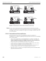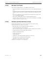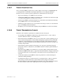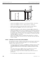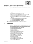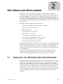
1
CHAPTER SITE DESIGN AND DEVELOPMENT 2 2 This chapter provides requirements and guidelines for site design and development. Site development refers to the civil, structural, mechanical, and electrical work; and installation of supporting equipment at a communications site. The chapter primarily discusses new site construction. Adding onto an existing site or installing a site in an existing facility requires that the scope of work, design and drawings be specific to these locations. It is recommended to consult with Motorola’s Site Design and Integration Team for new construction, co-location and renovation work. This chapter contains information on the following topics: • “Compliance with RF Energy Exposure Standards” on page 2-1 • “General Outline of Work” on page 2-2 • “Planning” on page 2-3 • “Constructability Review” on page 2-7 • “Electrical Service” on page 2-10 • “Foundation Design and Installation” on page 2-11 • “Concrete and Soils Installation Monitoring” on page 2-14 • “Site and Facility Acceptance Testing” on page 2-16 • “Tower Design and Construction” on page 2-16 The design and development of communications sites is critical not only to optimal functioning of the communications system, but also to the safety of installation and maintenance personnel involved with building and maintaining the system. The importance of implementing and following safety programs, during construction as well as during the system's useful life, cannot be overemphasized. All final construction drawings and specifications for a new site should be provided by a properly licensed engineering firm. This ensures that the design is adequate for the site conditions and helps ensure that accurate records of site construction are available. 2.1 COMPLIANCE WITH RF ENERGY EXPOSURE STANDARDS In planning, installing, or modifying any antenna tower or other antenna site, the need to comply with regulations and standards concerning human exposure to RF energy must be considered. Factors to be considered include (1) the location, direction, transmission power, frequency, physical characteristics, and design of all antennas and other equipment at the site, in light of the existing or possible human occupation or usage of the adjacent areas; (2) any necessary and appropriate steps to limit or control human access to adjacent areas, including limited-access doors, fencing, signs, and training; and (3) appropriate operational procedures to ensure ongoing compliance with RF energy exposure regulations and standards when the antenna site is operational. 68 P 81 08 9E 5 0- B 9 / 1/ 0 5 2-1 THE MOTOROLA SITE DESIGN AND INTEGRATION TEAM CHAPTER 2: SITE DESIGN AND DEVELOPMENT There should be a clear determination of who will be responsible for each aspect of compliance assurance, with the understanding that the operator or site owner bears ultimate responsibility for compliance. Additional information is provided in Appendix A. NOTE: All work shall conform to applicable codes and regulations imposed by authorities having jurisdiction. All contractors performing work at a site and all equipment vendors must be competent and qualified. A list of qualified contractors resides with the Motorola’s Site Design and Integration Team and the Motorola Environmental Health and Safety (EHS) director. 2.2 THE MOTOROLA SITE DESIGN AND INTEGRATION TEAM The Motorola Site Design and Integration Team (SD&IT) was developed to provide consistent and cost effective design and construction solutions utilizing key personnel with vast experience, expertise and knowledge in the public safety and construction arenas. The SD&IT key areas of expertise include, but are not limited to, site acquisition and leasing, zoning, architectural, engineering and environmental services, construction management, site preparation, site construction (including tower foundation and tower erection), co-location (including water tower and roof-top applications), outdoor cabinets and tenant build-outs. The Motorola SD&IT will be involved on a nationwide basis for all projects that involve any of the above stated activities. Motorola Site Design and Integration Team contacts will be available on the internal and external R56 websites. Additionally the SD&IT will own the responsibility for this R56 manual and its encompassing services. Contact information for the National Site Design and Integration Team: 2.3 • Site Development, A&E or Site Acquisition Questions: Bob Batis (989) 224-1330 • Product Questions: Gene McCurry (770) 673-5009 • Questions about this manual: Dan Kelly (708) 687-3224 GENERAL OUTLINE OF WORK The following is a high-level overview of major site development tasks and the order in which they are typically performed. 2-2 • Planning and site design drawing preparation • Site surveying/staking • Constructability review • Installing temporary facilities if necessary • Clearing land of vegetation • Installing erosion control barriers • Excavating and building access road • Installing utility/electrical metering base • Excavating and establishing subgrade and drainage requirements • Excavating and installing shelter and any ancillary foundations 68P81 089E50 -B 9/1 /05 STANDARDS AND 2.4 GUIDELINES FOR COMMUNICATION SITES • Excavating and installing tower foundations • Installing equipment shelter and ancillary equipment, including backup power systems • Installing electrical conductors and other utility installations • Energizing equipment shelter • Installing tower, antennas and RF transmission lines • Installing tower lighting system • Installing fencing and gates • Backfilling, grading, and bringing site up to final grade • Startup and testing of facility equipment • Performing final cleanup and obtaining customer approval signatures PLANNING PLANNING Planning the development of a communications site is crucial because the activities involved in constructing a site must be effectively organized in order to complete the project efficiently. 2.4.1 LOCATION OF UTILITY ENTRANCES All utility entrances (i.e., AC power, phone company, RF cables, water supply, gas supply, etc.) to the facility should be located in the same general area of the shelter and should be located as close together as is practical. 2.4.2 LOCATION OF AC POWER NEUTRAL-GROUND BOND Equipment performance and the susceptibility of a communications site to damage from lightning are affected by the location of the AC power neutral-ground bond. See “Location of Neutral-Ground Bond” on page 6-4. 2.4.3 SITE DEVELOPMENT DRAWINGS To help ensure that site development plans are developed in accordance with jurisdictional codes and specifications, it is highly recommended that an engineering firm be consulted. Typical site development drawings should include (but not be limited to) the following: 68 P 81 08 9E 5 0- B 9 / 1/ 0 5 • General compound and site layout relative to the surroundings • Location of access road if applicable • Location of existing utilities • Road profiles (cut and fill requirements) • Existing road profile 2-3 PLANNING CHAPTER 2: SITE DESIGN AND DEVELOPMENT • New road profile depicting road grade. Attempt to achieve a grade of less than 10%. Cranes, concrete trucks, and other heavy construction or delivery shipments must have access to the site. • True North/South and East/West Construction baselines as represented from the tower center (or center of site structure). NOTE: For guyed towers, it is imperative that the final elevation of the anchor head and final grade be coordinated between the foundation tower designer and site engineering firm. • Guy anchor location data schedule (if applicable). Typically the bottom of an anchor head should be 305 mm (12 in.) to 457 mm (18 in.) above final grade. • Foundation Plan, including general layout of all required foundations and foundation schedule depicting applicable foundation elevations • Grading Plan showing general grade elevation and slope of compound and access areas • Sediment Control Plan showing location of hay bales or silt fences to prevent soil erosion • Grounding system design showing all typical exterior grounding requirements. Soils resistivity measurements may also be depicted. • Typical access road cross section and culvert detail, showing the following: • • 2.4.4 • Cross section of access road • Drainage requirements • Curb cut requirements Equipment Shelter Foundation and details, showing the following: • Foundation layout (depth, length, and width of all foundations) • Cross-sectional view of foundations for rebar placement Utility plan and installation details, showing the following: • Layout and installation routes for required utilities • Types of instrumentation required if applicable • Electrical one-line and service installation details, showing electrical service installation. • Telephone Installation Details, showing type of telephone line installation if required • Fence enclosure and guy anchor fence plan showing fencing installation LAND SURVEY AND SITE DEVELOPMENT STAKING CONSIDERATIONS Prior to finalizing site development plans, the site surveying firm should supply the following items as a minimum: NOTE: Topographic and property boundary surveys shall be signed and sealed by a Registered Professional Engineer (or as required by jurisdictional law). 2-4 68P81 089E50 -B 9/1 /05 STANDARDS AND GUIDELINES FOR COMMUNICATION SITES PLANNING • Electronic (in compatible software version) and paper copies of property boundary surveys, clearly showing all easements, rights-of-way and boundaries. The property survey should be overlaid on the topographic survey to show property boundaries with respect to surface conditions. • Electronic (in compatible software version) and paper copies of topographic surveys showing all relevant surface conditions and characteristics, ensuring proper contour lines to convey relative surface height or depth. • East/West and North/South construction baseline delineation. • Latitude, longitude and elevation of proposed center of tower in relation to the communication compound. Site development staking should be performed upon completion of site development plans and required approval. It is recommended that site development staking be performed by the original surveying firm. The contractor performing the fieldwork and the surveyors should have a kickoff meeting to set expectations, understand and agree to a process that ensures timely execution. Electronic and paper copies of the completed construction drawings shall be transmitted back to the surveyor, to minimize the chance for errors in determining property boundary encroachment or engineering errors. At a minimum site development staking should include (but not be limited to): 2.4.5 • Easement/right of way locations • Temporary easement locations • Temporary and permanent roadways • Roadway curb cut and radius locations • Center of tower • Site fence corners • Center of tower leg locations • Building foundation corners • Center of inner and outer guy anchor locations TEMPORARY FACILITIES The following items are typically required during construction. Plan for these items before construction begins so they will be available when needed. 68 P 81 08 9E 5 0- B 9 / 1/ 0 5 • Staging, fabrication and construction areas • Drives, walks and bridges • Public access • Telephone • Sanitary and cleanup facilities • Drinking water • Light and power • Heat • Enclosures and storage 2-5 PLANNING 2.4.6 CHAPTER 2: SITE DESIGN AND DEVELOPMENT • Dumpsters and trash removal services (do not burn trash onsite.) • Restrictions on access to equipment shelter (do not use shelter as a workshop) • Personnel and tool trailers GEOTECHNICAL CONSIDERATIONS Geotechnical investigations are required for all projects that involve subsurface foundation installations, engineering design parameters and other related aspects of site development. Geotechnical data obtained in these investigations shall be provided to the tower and foundation designers and site engineering firm in a compatible electronic format. Unless otherwise specified, tower foundation and anchor design shall be executed in accordance with the latest revision of ANSI/EIA/TIA-222 (or other applicable local Standards body design requirements). It is highly recommended that the customer, tower and foundation designer, siteengineering firm and the appropriate Motorola representative hold a meeting to set expectations, requirements, parameters and the approval process to ensure timely completion of the designs. NOTE: Some contracts and geographical locations may require additional geotechnical information. Consult a reputable geotechnical firm, and the tower and foundation designer to ensure that all required geotechnical information is included in the report. • 2-6 Normal soil shall be defined as a cohesive type soil with: • a vertical bearing capacity of 19,530 kg/m2 (4000 lb/ft2) • a horizontal bearing capacity of 1,953 kg/m2 per 300 mm (400 pounds per square ft. per lineal ft.) of depth to a maximum of 19,530 kg/m2 (4000 lb/ft2). • Rock, non-cohesive soils, or saturated or submerged soils shall not be considered normal. • Pocket penetrometer tests should not be substituted for unconfined compression tests. • For each layer of soil encountered, the following items should be determined by field or laboratory testing and summarized in the soils report depending on the types of foundations recommended. • Standard penetration values • Soil classification and elevations • Angle of internal friction • Unconfined compression strength and cohesion • Tension and compression skin shear (for piles, caissons or drilled piers) • In-situ soil density and moisture content • Expected ground water fluctuations • When drilled piers are feasible, the plasticity index and over-consolidation ratio shall be determined. • The recommended type(s) of foundations to be considered, and corresponding design parameters for uplift, compression and lateral load • Construction techniques to ensure the design parameters are obtained. 68P81 089E50 -B 9/1 /05 STANDARDS AND 2.5 GUIDELINES FOR COMMUNICATION SITES CONSTRUCTABILITY REVIEW CONSTRUCTABILITY REVIEW The constructability review leverages construction knowledge and experience in planning, design, procurement and field operations to achieve overall project objectives. All project parties should become involved in a constructability program at the onset of a project to ensure there is a maximum influence on overall cost, quality, cycle time and functionality. Outlined below are some of the basic steps for a constructability review. 2.6 • Establish criteria for selection of members • Establish constructability objectives/concepts • Establish project objectives (scope) relative to constructability objectives • Compare contractual scope objectives and constructability objectives with requirements of this manual • Establish roles and responsibilities • Establish the importance of teamwork • Determine level of formality for constructability program • Define specific constructability procedures • Integrate constructability into project activities • Identify appropriate measures for objectives SITE WALKS As defined here site walks refer to post contract award. Site walks familiarize involved parties with the development plan for a proposed site. After a site's use has been confirmed, a site walk shall be conducted to examine as much detail about the site as possible, and to clearly determine and describe responsibility for all aspects of the site development. It is recommended where practical that all involved parties participate in a site walk. This includes but is not limited to geotechnical, site engineering, the site design team or site design team designee, contractor, and the customer personnel. This saves time, encourages multiple opinions, and ensures that all parties agree on preliminary layouts. At a minimum, the following items should be completed during the site walk: 68 P 81 08 9E 5 0- B 9 / 1/ 0 5 • Choose the specific location of the facility. (If survey information is not available or applicable, precise location information is required for future reference and equipment deliveries). • Note general condition of site and surrounding area, including pre-existing flooding or erosion conditions. Note site characteristics and any notable items from the surrounding properties. • Discuss site layout. General agreement and concurrence should be reached on preliminary site layout and development with respect to the site and its characteristics. • Verify the location of the nearest commercial utility/electrical service. If available, note the name of the service provider along with a service pole number or approximate location of nearest service pole. • Observe accessibility. Access to the site is of the utmost importance and should be thoroughly investigated and noted at this time. Any obvious easement or security issues should be noted and investigated also. 2-7 SITE WALKS CHAPTER 2: SITE DESIGN AND DEVELOPMENT • Observe and investigate weight (load) considerations. Load restrictions, whether on the access road, elevator or floor, should be thoroughly investigated and noted at this time. Obtaining special permits if required to access a site may be time-consuming. NOTE: Without proper investigation and planning, load restrictions can prevent a site from being used. • Note potential environmental concerns such as wetlands, dump site, oil spills, garbage piles, nearby truck stops, and fueling stations. • Note the type of property (existing facility, building top, private, state, or federal property). • The construction location should be relatively clear of trees and brush. There should be an adequately sized layout/fabrication area adjacent to the construction area; lack of such area may hinder cost-effective construction. • The construction location should be on level, firm land free of drainage and soil erosion problems. • In locations where permafrost exists, the building must be isolated from the surrounding earth. Even the small temperature differential presented by an equipment shelter may be sufficient to melt the surface soil, leading to major structural and foundation damage. Workable solutions include building the structure on stilts or insulated pilings. Though it is also possible to construct on bedrock, special methods for anchoring and grounding must be used. • If it is recommended or required that an existing tower or structure be used to support proposed additional antennas and transmission lines, then the original designer should perform a structural and foundation analysis. NOTE: It may be impractical or impossible to add more antennas to an existing tower or structure due to the retrofitting required or the physical limitations of the tower, structure or foundations themselves. • If it is recommended or required that an existing tower or structure be used to support proposed antennas and transmission lines, the site should be observed for potential electromagnetic energy (EME) issues. An interference analysis shall be performed to determine interference that may exist at the location. Additionally, these tasks may be recommended to be performed based on the initial site walk: 2-8 • On existing facilities, perform a preliminary R56 compliance inspection to ensure proper planning and advisement to the customer (if required). Ensure proper testing and measurement of existing ground system integrity, if practical. • Perform four-point soil resistivity testing if required. See “Soil Resistivity Measurements” on page B-1. • Take subsurface soil core samples for soil resistivity if practical. 68P81 089E50 -B 9/1 /05 STANDARDS AND 2.7 GUIDELINES FOR COMMUNICATION SITES PERMITTING, ZONING, CODE AND REGULATORY CONSIDERATIONS PERMITTING, ZONING, CODE AND REGULATORY CONSIDERATIONS Obtaining permits and complying to local codes, ordinances and regulations can be complicated and time-consuming. It is highly recommended that all involved parties carefully plan and execute this portion of the project. To avoid unexpected problems, confer with all authorities having jurisdiction before beginning construction, and provide them with clear execution plans. To assist with permitting, zoning, code and regulatory considerations, it is recommended that the Motorola Site Design and Integration Team be consulted. Some municipalities require that all communications installations which will share public safety facilities (police or fire stations, hospitals, etc.) must be constructed to standards under the State “Essential Services Act.” This requires that seismic upgrading and installation practices be met, and emergency power systems be upgraded to handle the new demand for the entire facility, sometimes at considerable additional costs. Even if the shared communications site lease does not specifically identify the need to comply with Essential Services Act standards, there may be “catch all” clauses which state that “all applicable local, state, and federal laws and requirements shall be met.” 2.7.1 AMERICANS WITH DISABILITIES ACT CONSIDERATIONS NOTE: The following specifically applies to sites located within US jurisdiction. However, other jurisdictions may have similar or more stringent requirements. In all cases, the more stringent requirement takes precedence. The Americans With Disabilities Act (ADA) is a US federal program signed into law as Public Law 101-336 July 26, 1990 104 Statute 327. Of greatest importance regarding a communications site is the following language contained in Title I which requires that: “...business must provide reasonable accommodations to protect the rights of individuals with disabilities in all aspects of employment.” At communications sites, this may result in changes in workstations and work areas to provide required accommodations. Some effects on a communication site regarding ADA compliance are: • Providing extra-wide entry doors • Providing a ramp for building access, a hand rail, and a turnaround area for wheelchairs within the building • Providing convenient placement of telephones and light switches • Providing dedicated paved handicap parking spaces While some domestic municipalities are not yet requiring ADA compliance, many large cities are. Such regulations may significantly affect communications site development. The Uniform Building Code (UBC), Chapter 31 Accessibility, addresses these requirements in detail. UBC Chapter 31 Article 3104(3), Egress, in part, specifies a requirement for a 1.22 m (48 in.) width doorway. Article 3104(4), Article 3105 Facility Accessibility, requires that a telephone or other communications system shall be available. 68 P 81 08 9E 5 0- B 9 / 1/ 0 5 2-9 FIRE SUPPRESSION 2.7.2 CHAPTER 2: SITE DESIGN AND DEVELOPMENT FEDERAL CLEAN WATER ACT CONSIDERATIONS The Federal Clean Water Act (FCWA) shall be considered during site development. FCWA programs administered by local governments sometimes vary with different requirements and enforcement for specific locations. The FCWA may require that common HVAC system condensate water be carried to a legal building drain system and may not be disposed of in the ground soil. This may result in requirements to include condensate pumps on HVAC systems and to plumb the HVAC condensate water to a proper sewer system. 2.8 FIRE SUPPRESSION Fire is a hazard that must be taken into account when designing a communications room or structure. An appropriate means of preventing and controlling the spread of fire must be provided to help protect people sharing the structure or working with the equipment. Appropriate fire detection and suppression is typically required at communication sites where persons are manning the facilities. Where applicable, these facilities shall be designed in accordance with local jurisdictional codes. 2.9 ELECTRICAL SERVICE The following list is provided to help organize, manage, and coordinate electrical service installation. Some items may not apply to all projects. Ensure that the electrical installation process is tracked, managed and documented by responsible parties. • It is recommended that one person from the utility company be established as the point of contact. Ensure that the utility company's work order tracking methods and processes are understood. Typically a customer tracking number is assigned. • Where practical, keep overhead lines and poles at least 61 m (200 ft.) from the site compound area during construction. This helps protect against accidental contact by construction or maintenance equipment and hazards associated with ice falling from the tower while under construction. • To facilitate single-point grounding, request that electrical service enter the site building on the same wall as and near to the entry point for the antenna transmission lines. • Proper separation between overhead electrical service conductors and antenna transmission lines shall be a minimum of 0.6 m (2 ft.) (NFPA 70-2005, Article 810.13). This may require coordination between the site development engineer and the shelter manufacturer to ensure consistency in layouts. • Utility installations are jurisdictional. Ensure that it is clearly understood who the utility supplier will be. This is best achieved with a site meeting. • Coordinate other utility installations such as closed-circuit television (CCTV) and telephone company. • Supply the utility with an electrical utility information form. NOTE: Additional site-specific load or use information, such as type of equipment, generator or uninterruptible power supply (UPS) information, may be required. • 2-10 Obtain an installation cost estimate from the utility company. 68P81 089E50 -B 9/1 /05 STANDARDS AND GUIDELINES FOR COMMUNICATION SITES • FOUNDATION DESIGN AND INSTALLATION It is imperative that the proper easement paperwork shall be obtained and provided to the utility. NOTE: Governmental agencies transferring land or granting easements may take considerably more time than private landowners. • A copy of the utility site installation sketch, staking sheet or overlay shall be obtained. It is imperative to check that the utility company interpreted the request for service correctly and that they have conformed to easement restrictions. It is easier to correct problems in the design phase than after service installation has started. • Typically, final electrical service connection to the meter pedestal will not take place until the utility has been paid. • The utility company usually requires a site address before they will connect power. Utility companies may or may not assign the address. It is more likely the local township will assign the address. • A jurisdictional electrical inspection is usually required before the utility company connects power. • The electric meter, but not the meter pedestal, is typically supplied by the utility. Verify who is responsible for providing the electric meter. • Electrical service installations in very cold climates are typically much more expensive and likely to slow the installation schedule. NOTE: When a soil boring test is performed, the local soil resistivity, soil pH and the type and concentration of dissolved salts should be established to aid in the design of the grounding electrode system. (TIA/EIA 222-F-R2003). See “Dissimilar Metals and Corrosion Control” on page 4-34. 2.10 FOUNDATION DESIGN AND INSTALLATION 2.10.1 FOUNDATION AND GEOTECHNICAL SERVICES Foundation monitoring services are required when structural soils and foundation work is performed. They may also be required for certain other sub-surface and surface work. Monitoring services report whether the soils and concrete conform to design limits specified by either the tower and foundation designer or site engineering firm before, during or after installation. If the specified design limits are not met, the foundation monitoring service shall notify the contractor and Motorola to ensure that the noncompliance is corrected. This service is sometimes performed by the geotechnical firm. WARNING To prevent accidental damage to underground utilities, always have the local utility company or utility locator service locate the underground utilities before excavating or digging at a site. NOTE: Firms offering this service may be able to provide a checklist to use as a guideline for the project. 68 P 81 08 9E 5 0- B 9 / 1/ 0 5 2-11 FOUNDATION DESIGN AND INSTALLATION 2.10.2 CHAPTER 2: SITE DESIGN AND DEVELOPMENT CONCRETE FOUNDATION DESIGN AND INSTALLATION CONSIDERATIONS This paragraph describes the design and construction considerations and requirements for communications site concrete foundations, including prefabricated communications shelter foundations and tower foundations. NOTE: If concrete encased electrodes (Ufer grounds) are to be utilized, they must be addressed, engineered and installed before the concrete is poured. See“Concrete-Encased Electrodes” on page 4-20. 2.10.2.1 PLANNING 2-12 • Foundation design for prefabricated shelters and other equipment shall be based upon site soil conditions as noted in the geotechnical report. These foundation plans for buildings and ancillary equipment shall be designed by a licensed Professional Engineer and the design shall be included in the construction drawing package. • A Professional Engineer or contracting firm shall determine whether the soil is adequate to properly support the concrete foundation or slab. The Professional Engineer or contracting firm shall determine the excavation depth and the required fill, if required. • To ensure personnel safety, all excavations shall be conducted in accordance with Occupational Safety and Health Administration (OSHA) safety and excavation regulations, or other applicable Occupational Safety and Health standards and/or local safety regulations (whichever is most stringent). • All foundation designs shall be approved by contracted Professional Engineer or contracting firm prior to commencement of work. • A concrete foundation is typically used for building and shelter installations. If a foundation is used, the foundation shall be appropriate for the structure. • All foundation construction shall be performed by a qualified contractor specializing in this work. • If a site is to use concrete-encased grounding electrodes within the foundation or other concrete structures, appropriate measures shall be taken to accommodate the grounding system within a concrete structure before the concrete is poured. (See Chapter 4, “External Grounding (Earthing),” for additional information.) • A foundation for a prefabricated shelter shall be built in accordance with the manufacturer's specifications and site specific soil conditions. The Architectural and Engineering firm providing the construction drawings will coordinate and include final foundation designs in the drawings. • Foundation design shall consider any precipitation conditions unique to the location. These considerations include (but are not limited to) elevated (pier type) platforms used in low-lying areas prone to regular flooding, and elevated foundations used to prevent burial of site due to snowfall. Special foundation designs include: • Footings • Piers • Columns • Grade beams 68P81 089E50 -B 9/1 /05 STANDARDS AND GUIDELINES FOR COMMUNICATION SITES FOUNDATION DESIGN AND INSTALLATION 2.10.2.2 PREPARATION • All excavations on which concrete is to be placed shall be substantially horizontal on undisturbed and unfrozen soil and shall be free of loose material and excess ground water. Methods for removing excess ground water shall be provided if required. • The foundation area shall be graded to provide water runoff and prevent water from standing. The final grade shall slope away in all directions from the foundation. 2.10.2.3 POURING • Concrete forms of wood, metal centering, cores, molds, and so forth, shall be used as required for the proper execution of the plain and reinforced concrete work. Sufficient quantities shall be used to properly execute and expedite work without endangering the safety or strength of any part of the construction. • All forming shall be true and rigid, thoroughly braced, and sufficiently strong to safely carry all dead and live loads to which it may be subjected. The elimination of forming by a monolithic pour against undisturbed soil shall be allowed only if approved by a soils engineer and/or a qualified Motorola representative. • All steel reinforcement shall be furnished and installed in accordance with the approved foundation drawing. Unless otherwise specified or shown on plans, reinforcement shall consist of preformed bars of intermediate grade, manufactured from new billet stock. Metal reinforcement shall conform to the requirements of the latest version of Specifications for Deformation of Preformed Steel Bars for Concrete Reinforcement, ASTM A615-68, or applicable jurisdictional code, whichever is more stringent. • Anchors, bolts, and miscellaneous iron work shall be set as shown in the drawings before pouring concrete. Embedded items shall be held rigidly in place during placing and curing of concrete. Placing rebar in position as the concrete is placed shall not be permitted. • Concrete shall be vibrated and thoroughly consolidated around all embedded items. • At least one week prior to all concrete pours, the proposed concrete mix design shall be submitted to Motorola or its contractor for verification of design specifications. • When concrete is placed, certificates shall be furnished for each delivery vehicle or every 5.4 m3 (7 cu. Yds), showing the mix proportions, additives, compressive strength, and the brand name and type of cement. • Concrete shall be so deposited that there will be no separation or segregation of aggregate. Maximum free drop shall not exceed 2.43 m (8 ft.). • Concrete shall not be placed when the outdoor temperature is below 4.5° C (40 degrees F) nor when the concrete is likely to be subjected to freezing temperatures before final set, except when adequate provisions have been made for protection. When deposited in the forms, the concrete shall have a temperature of not less than 15.5° C (60° F) and not more than 32° C (90° F). A suitable means shall be provided to maintain the temperature above 10° C (50° F) for 7 days. The materials shall be heated before mixing to prevent concrete from freezing. 2.10.2.4 BACKFILLING • 68 P 81 08 9E 5 0- B 9 / 1/ 0 5 After completion of the foundation and other construction below grade, and before backfilling, all excavations shall be clean of vegetation, trash, debris, and inorganic materials. 2-13 FOUNDATION DESIGN AND INSTALLATION 2.10.3 CHAPTER 2: SITE DESIGN AND DEVELOPMENT • A soils engineer shall determine if the onsite excavated materials are adequate or suitable for use as backfill material. If the material is not suitable, then engineered soils shall be determined by the soils engineer. • Foundation backfill shall be placed in layers no more than 305 mm (12 in.) deep before compaction. The backfill requirements of each site differ based on conditions at the site. • A foundation for a cabinet shall be level and sealed. CONCRETE AND SOILS INSTALLATION MONITORING Test requirements for different types of concrete foundations are provided in Table 2-1. TABLE 2-1 FOUNDATION AND SOILS MONITORING REQUIREMENTS Requirement Confirm and obtain concrete mix design from foundation designer. Type of Foundation Drilled Piers (Caissons) X Perform penetrometer test at the base of the mat or tower excavation to verify soil bearing conditions. The number of test locations is dependent on soil conditions. The Geotechnical firm shall provide bearing values for specific locations. Deep Mat Guy Tower Sites Eqpt. Shelter Found ations X X X X minimum 3 to 5 locations X minimum 2 to 3 locations X minimum 2 to 4 locations X X X NOTE: Penetrometer tests are not required at the bottom of guy anchor thrust block excavations. Collect bulk sample for Modified Proctor compaction testing. Expedite sample to lab to accommodate a 7-day concrete cure period (unless a high early type mix is used) then a shorter turnaround is required. Identify specific caisson(s) being installed and include in daily field log and concrete report. X Confirm and note caisson diameter and depth in concrete report. X Confirm, note and ensure caisson bottom is clean and free of debris. X For caissons, confirm and note placement of reinforcement cage and ensure it is centered in caisson pier. X X X X X X X X For other foundations, confirm and note placement of reinforcement steel with respect to foundation design. Confirm and note that method of concrete placement is as specified by foundation designer(s). 2-14 68P81 089E50 -B 9/1 /05 STANDARDS AND GUIDELINES FOR COMMUNICATION SITES FOUNDATION DESIGN AND INSTALLATION TABLE 2-1 FOUNDATION AND SOILS MONITORING REQUIREMENTS (CONTINUED) Requirement Type of Foundation Deep Mat Guy Tower Sites Eqpt. Shelter Found ations X X X X Confirm and note that a working vibratory wand is used to consolidate the upper 3 m (10 ft.) of concrete placed in each caisson or the tower mat foundation. X X X X Ensure that newly formed test cylinders are placed in an insulated cure box or other heated area to protect against freezing temperatures. Note that other methods of curing may be more acceptable or desired. X X X X Test concrete cylinders in accordance with latest version of American Concrete Institute (or authority having jurisdiction) standards and note in concrete test log. X X X X Note unusual developments such as rejected concrete, weather or construction delays, difficulty in setting anchor bolts, or casings stuck in place. X X X X Perform, confirm and note density tests on each new lift of tower foundation backfill to verify it is compacted to 95% of the Modified Proctor maximum density value test (ASTM D1557). Note the type of compacting equipment used. X X X X Drilled Piers (Caissons) Perform concrete field tests (slump, temperature and air content) and cast a minimum of one set of test cylinders (four cylinders per set) for every 19.1 m3 (25 cu. yd.) of concrete placed. Perform new set of tests and cylinders once five yards beyond the 19.1 m3 (25 cu. yd.) increment. Examples: 61 m3 (80 cu. yd.) = four sets of test cylinders. 23 m3 (30 cu. yd.) = two sets of cylinders). Specifically note the anchors or locations worked on and the order in which they were poured. Ensure backfill and undercut areas for non-structural applications (such as around pre-fabricated shelter foundations) are compacted to 90% of the maximum dry density value determined by the latest version of Standard Proctor test (ASTM D698). 68 P 81 08 9E 5 0- B 9 / 1/ 0 5 X X 2-15 SITE AND FACILITY ACCEPTANCE TESTING 2.11 CHAPTER 2: SITE DESIGN AND DEVELOPMENT SITE AND FACILITY ACCEPTANCE TESTING When site development, including tower construction, antenna and transmission line installation, utility connection, building or shelter placement or construction, and roadway construction, is complete, all applicable areas of the site shall be inspected and tested, to ensure that all installations and alarms are functioning properly before the site is presented for customer acceptance. All aspects of the inspection and testing shall be documented. Items to inspect and test may include but are not limited to the following: 2.12 • Site AC power and alarms • Transfer switch functionality and alarms • HVAC equipment and alarms (including high and low temperature and high humidity) • Generator functionality and alarms • Fire or smoke detection devices • UPS functionality and alarms • Tower lighting functionality and alarms • Dehydrator functionality and alarm • Security measures such as door alarms and deadbolts • Antenna and transmission line installations • Concrete compressive strength requirements • All aspects of the site, building and tower drawings are met or properly as-built • General workmanship • Site and building are clean and free of trash and debris • Tower installation is in accordance with the latest version of ANSI/EIA/TIA-222 (or other applicable local Standards body design requirements) • R56 audit TOWER DESIGN AND CONSTRUCTION When designing a tower site with a related equipment shelter, it is recommended that the tower be placed a minimum of 9.1 m (30 ft.) from the shelter when possible. This distance provides a balance between line loss in the antenna transmission line and the reduction in the amount of electromagnetic energy (EME) induced into the shelter in the event of a tower lightning strike. The separation will also help increase the ability of the tower grounding electrode system to dissipate the lightning energy before it reaches the shelter. It is recommended that the distance between the tower and the shelter be no less than 3 m (10 ft.) to help prevent ice damage to the building, and EME effects. NOTE: Increasing the distance between the tower and shelter from 3 m to 9.1 m (10 ft. to 30 ft.) reduces the amount of EME induced into the building by a factor of 9 (EME reduction factor = distance factor2). For example, increasing the distance by a factor of 3 (from 10 ft. to 30 ft.) results in an EME reduction factor of 32, or 9. 2-16 68P81 089E50 -B 9/1 /05 STANDARDS AND GUIDELINES FOR COMMUNICATION SITES TOWER DESIGN AND CONSTRUCTION NOTE: Twist and sway of a tower affects the performance of microwave links. Therefore it is imperative that the proper loading information for each tower shall be supplied to the tower designer to help ensure that the tower meets ANSI/EIA/TIA-222 (or other applicable local Standards body) requirements. All tower and tower loading design shall be performed by a registered professional structural engineer. If a structure other than a tower will be used to support a communication system antenna, the tower designer and/or a registered professional engineer specializing in tower structure design shall be contracted to analyze whether the structure can safely support the proposed load. Tower mapping may also be required. Tower height is determined by a number of factors, including but not limited to the following: • Required RF coverage • Location • Seismic risk probability • Available area • Existing structures in the vicinity • Terrain • Required antenna height • Federal Aviation Authority (FAA) or jurisdictional approval • Future tower capacity Unless otherwise specified, all towers and foundations shall be designed to the latest version of ANSI/ EIA-TIA 222 unless jurisdictional laws or codes mandate otherwise. The following tower design requirements apply: • A minimum of one safety climb shall be engineered, supplied and installed on every tower. • EME precautions shall be as described in Appendix A. • Rest platforms shall be designed and installed per OSHA or other applicable Occupational Safety and Health standards, or as recommended by the tower manufacturer. If additional antennas are to be added to an existing tower, or if a structure other than a tower will be used to support a communication system antenna, the original tower vendor and/or a registered professional structural engineer shall be contracted to analyze whether the tower or structure can safely support the additional load. Tower mapping may also be required. Table 2-2 provides a brief comparison of the three most common tower types. 68 P 81 08 9E 5 0- B 9 / 1/ 0 5 2-17 TOWER DESIGN AND CONSTRUCTION CHAPTER 2: SITE DESIGN AND DEVELOPMENT TABLE 2-2 COMPARISON OF TOWER TYPES Factor Self-Supporting Cost Guyed Monopole High Moderate More material required More assembly cost required Foundation more expensive Land costs may be higher because more area is required for guy wires. High Moderate Self-supporting structure is typically more stable and better able to resist wind loading. Provide resistance to wind sway, but are susceptible to torquing, especially when dish antennas are installed. Land Required Low High - Location of guy anchors must be far from tower, requiring more property. May be unsuitable for populated areas due to land requirements Low - Well-suited for urban areas with limited land availability. Height Moderate High - Guyed towers may exceed 366 m (1200 ft.) Low Growth Potential Moderate Moderate Low - Monopoles capable of supporting growth with room to rent space to other users may cost significantly more to build. Rigidity 2.12.1 Moderate based on loading Low - wind resistance less than other types. TOWER DESIGN DRAWINGS Tower foundation drawings shall show the following information at minimum: 2-18 • Reference to the soil/geotechnical report, including file number, date and firm performing report, used in calculations and design. • Required concrete compressive strength to be achieved at 28 days • Grade and/or type of reinforcing bar • Concrete coverage requirements • Whether welding of rebar is permitted • Whether cold joints are permitted; if so, the joining procedure shall be specified. • Whether permanent steel casings are permitted for caisson installations • Whether temporary steel casings are or may be required due to the expected soil conditions • Any recommended concrete installation techniques such as a tremie • References to all codes (and sections of codes) applicable for the design 68P81 089E50 -B 9/1 /05 STANDARDS AND GUIDELINES FOR COMMUNICATION SITES • 2.12.2 TOWER DESIGN AND CONSTRUCTION Plan, elevation and section views depicting a minimum of the following: • Length, depth, and width • Diameter • Finish grade with respect to top of foundation • Rebar size and placement • Anchor bolt size, type and placement • Above finish grade requirement for anchor heads (typically a minimum of 305 mm (12 in.) • Estimated cubic yards of concrete per pier, caisson, mat, block or other type of foundation • Backfill requirements such as but not limited to: • Material type • Thickness of lifts (typically lifts not more than 305 mm (12 in.) thick are acceptable). • Applicable compaction requirements; such 95% of modified proctor maximum dry density. • Applicable sub-grade compaction requirements; such as for a guy anchor. Upon completion of the excavation the designer may require certain compaction densities. • Any other pertinent information that may be abstracted from the soils report, such as a high water table or large boulders. • Any other pertinent construction or design information or considerations. DESIGN CONSIDERATIONS TO HELP REDUCE EFFECTS OF LIGHTNING Site design and physical layout can affect the susceptibility of a communications site to damage from lightning. The following topics are given as options to help reduce the harmful effects of lightning at a communications site. 2.12.2.1 POINT OF ENTRY FOR RF TRANSMISSION LINES Reducing the height at which the RF transmission lines (coaxial cables) leave the tower and enter the building can reduce the susceptibility of a communications site to damage from lightning (Figure 2-1). The reduction in height reduces the voltage on the RF transmission lines before they enter the facility. A suggested best practice is for the coaxial cables to enter the facility at a maximum height of 610 mm (2 ft.) above the facility floor (United States National Weather Service Manual 30-4106-2004, “Lighting Protection, Grounding, Bonding, Shielding, and Surge Protection Requirements”). 68 P 81 08 9E 5 0- B 9 / 1/ 0 5 2-19 TOWER DESIGN AND CONSTRUCTION CHAPTER 2: SITE DESIGN AND DEVELOPMENT COAXIAL GROUNDING KITS COAXIAL GROUNDING KITS SHELTER SHELTER IN-LINE PROTECTOR IN-LINE PROTECTOR 1 2 COAXIAL GROUNDING KITS COAXIAL GROUNDING KITS SHELTER SHELTER IN-LINE PROTECTOR IN-LINE PROTECTOR 3 4 FIGURE 2-1 TRANSMISSION LINE ENTRY POINTS (IN ORDER OF PREFERENCE) NOTE: The point of entry for RF transmission lines is especially important at facilities that are normally occupied, such as dispatch centers, and at facilities that are located on above-ground platforms (usually for the purpose of flood control). See Figure 3-6 on page 3-9 for an example of a shelter located on an above-ground platform. 2.12.2.2 DISTANCE BETWEEN TOWER AND BUILDING Increasing the distance between the tower and building may reduce the susceptibility of a communications site to damage from lightning. Increasing the distance between the tower and building has the following benefits: 2-20 • It decreases the magnetic field associated with lightning that is coupled into the building. The amount of magnetic field coupled into the building decreases by the square of the distance. For example, the magnetic field coupled into a building would decrease by a factor of nine (9) if the distance between the tower and building is increased by a factor of three (3). • It reduces the amount of energy that reaches the building via the RF transmission lines. This is because of the increase in inductance of the longer transmission lines. • It reduces the amount of lightning energy that is propagated through the earth from the tower grounding (earthing) electrode system to the building grounding electrode system. • Nine metres (30 feet) is considered a good compromise between protection level benefits and the length added to RF transmission line. 68P81 089E50 -B 9/1 /05 STANDARDS AND GUIDELINES FOR COMMUNICATION SITES TOWER DESIGN AND CONSTRUCTION 2.12.2.3 METALLIC TELECOMMUNICATIONS/DATA LINES Whenever practical, metallic telecommunications/data lines should be eliminated from the facility. Metallic telecommunications/data lines provide a conductive path into the facility for lightning energy. Elimination of metallic telecommunications/data lines through the use of fiber optic cable (or other isolation device) provides isolation from lightning-induced ground potential rise (GPR) and lightning energy. 2.12.2.4 ISOLATION OF BUILDING AND TOWER FROM ICE BRIDGE/CABLE BRIDGE NOTE: Applies to tower and/or building-supported ice bridges and cable bridges. In order to reduce the amount of lightning energy diverted toward the equipment building/shelter, and to provide seismic isolation between the building and tower, it is recommended that the cable bridge/ice bridge be secured to the tower using a non-conductive slip-joint type device. When a slip-joint type device is used, grounding of the cable bridge/ice bridge shall be completed as described in “Cable Bridge/Ice Bridge Grounding (Earthing)” on page 4-71. 2.12.2.5 USE OF AIR TERMINALS ON TOWERS The use of air terminals (lightning rods) on a tower may be appropriate in some circumstances to protect antennas from a direct lightning strike. If the tower is over 45.7 m (150 ft.) tall, side-mounted antennas are vulnerable to direct lightning strikes. Side-mounted antennas installed at a height greater than 45.7 m (150 ft.) may be protected through the use of horizontal lightning rods. The horizontal lightning rods are attached to the tower, just above and below the antenna. PROTECTED AREA NON-PROTECTED AREA HORIZONTAL LIGHTNING RODS SIDEMOUNTED ANTENNA PROTECTED AREA NON-PROTECTED AREA FIGURE 2-2 USING HORIZONTAL LIGHTNING RODS TO PROTECT SIDE-MOUNTED ANTENNA 68 P 81 08 9E 5 0- B 9 / 1/ 0 5 2-21 TOWER DESIGN AND CONSTRUCTION 2.12.3 CHAPTER 2: SITE DESIGN AND DEVELOPMENT TOWER SAFETY Always observe the following safety guidelines when working with towers. 2.12.4 2-22 • Towers shall be erected and installed by bonded contractors specializing in such work. • Any area involving tower construction shall be tied off to restrict entrance by unauthorized personnel. • Fall protection measures shall be observed and implemented at any and all towers and structures, regardless of ownership, where climbing is required. • Any and all applicable regulations regarding tower climbing shall be observed and implemented. The most stringent regulations shall supersede other regulations. • Subcontractors shall be required to submit their written comprehensive Safety Program to Program Management and obtain approval prior to commencing any work. • All tower climbing shall be in accordance with the Motorola Contractor Fall Protection Program. • Towers shall not be overloaded. • OSHA or other applicable Occupational Safety and Health standards regulations shall be observed in all phases of tower construction and maintenance. REGULATIONS AFFECTING TOWERS • In the United States, the Federal Aviation Administration (FAA) regulates and approves towers, including but not limited to tower height, location, marking, and lighting. Each state or jurisdiction may have additional regulating agencies which may designate specific marking or lighting requirements in addition to FAA requirements. It is highly recommended that the appropriate authorities having jurisdiction be identified and consulted before final tower design and construction begins. • CFR 47, Part 17 – “Construction, Marking and Lighting of Antenna Structures” shall be followed to determine required paint markings and lighting for towers. Equivalent local standards shall be followed for nondomestic installations. • A preconstruction notice shall be submitted to the FAA or local authority having jurisdiction at least 30 days before the date the proposed construction or alteration is scheduled to begin, on or before the date a construction permit application is filed with the Federal Communications Commission (FCC). Ensure that the FAA acknowledges receipt of the notice before beginning tower construction. Other notices may be required by the FAA on a case by case basis. • All FAA, FCC, and jurisdictional rules and regulations shall be strictly followed throughout tower design and construction, and following tower completion. It is highly recommended that the appropriate authorities having jurisdiction be consulted before starting tower design and construction. • Unless otherwise specified, tower foundation and anchor design shall be in accordance with the latest revision of ANSI/EIA/TIA-222 (or applicable local Standards body design requirements) or local jurisdictional code, whichever is more stringent. 68P81 089E50 -B 9/1 /05 STANDARDS AND GUIDELINES FOR COMMUNICATION SITES 2.12.5 TOWER DESIGN AND CONSTRUCTION SECURING THE TOWER After construction, unauthorized entry to a tower shall be controlled as follows: 2.12.6 • Install a fence around the tower. The fence should be at least 1.8 m (6 ft.) high with barbed wire at the top. • The guy piers of guyed towers should also be fenced with a gate and lock to help prevent accidental or malicious damage to the guy wires. A damaged or weakened guy wire could cause the tower to fall. • If the tower has climbing pegs, the pegs should be removed from the bottom 6.1 m (20 ft.) of the tower to deter unauthorized climbing. • If the tower has a climbing ladder or elevator, it should be appropriately secured. • Appropriate signage notifying restricted access to the tower area and identification of tower shall be affixed to the fence in a conspicuous location. ANTENNA AND DISH ANTENNA LOADING Antenna loading requirements are one of the most critical aspects of tower design. Loading requirements include but are not limited to the following: • RF antenna quantity, size, type, manufacturer, frequency, and elevation • If required, future RF antenna loading requirements • Microwave dish antenna quantity, size, manufacturer, frequency, azimuth, elevation, and radome • If required, future microwave dish antenna loading requirements • Transmission cable diameter and type • Sidearm length and location • Lighting requirements • Additional ice or wind loading requirements applicable to the selected site • Safety apparatus such as climbing ladders and rest platforms • Miscellaneous optional equipment, such as ice shields See Figure 2-3 for an example of a tower loading report. 68 P 81 08 9E 5 0- B 9 / 1/ 0 5 2-23 TOWER DESIGN AND CONSTRUCTION Site Designator 7XXX MSP No 7XXX CHAPTER 2: SITE DESIGN AND DEVELOPMENT Tower Loading Information NewTown City County Charles Phase 3 District 7 Tower Type: Self Support Tower Reference Azimuth: 0 Ant. Engineering File Number: Microwave Antenna System Information Path No Path Destination Path Density Radio Capacity 21-Dec-99 Tower Height: 475 Azimuth Path Distance Antenna Height (CL) Dish Size Space Diversity Diversity Ant. Ht (CL) Div Dish Size ERIP (dBi) Polarization 91 7203b high 28 43 14.8 135 6 95 6 66.8 Vertical 88 7302p4 medium 12 121.4 10.6 142 6 102 6 66.8 Vertical 89 7001b high 28 160.605 11 160 6.1 99 6 64.8 Vertical 90 7904p1 High 28 237.145 15.8 125 8 80 6 69.3 Vertical 101 7804c high 28 333.9 11.4 106 6 71 6 66.8 Vertical Site Designator 7XXX MSP No 7XXX City County Tower Loading Information NewTown Charles Phase 3 District 7 Tower Type: Self Support Tower Reference Azimuth: 0 Ant. Microwave Antenna System Information Path No Path Destination Path Density Radio Capacity 800 MHz Antenna Information One 800 MHz Rx Ant. Ht: Number of 800 MHz Tx Ants: Mounted at a Height of: Model Number of Antennas: NOTES: Azimuth Path Distance Model Number of Antennas: 2 Mounted at a Height of: 475 Quantity of Antennas: PD100175a Engineering File Number: Dish Size Space Diversity Diversity Ant. Ht (CL) All Line for the non 800 MHz Antenna Systems will be 7/8" Heliax If tower is less than 250' mount relocated existing antennas at highest available location. ERIP (dBi) Polarization Marked (Painted): Medium Intensity White: 200 3 Div Dish Size Tower Marking and Lighting Requirements DB212 Dual Medium Intensity (White and Red): NOTE: All Line for the 800 MHz Antenna Systems will be 1 5/8" Heliax 1 5/8" Snap in hanger required for the site. Antenna Height (CL) Relocated Existing Antenna Systems Loading Requirements 445 21-Dec-99 Tower Height: 475 High Intensity White: Dual High Intensity (White and Red): Conventional Red Lighting: 61 Requires No Lighting: Notes: 1. Compliance with future loading requirements mandates doubling all RF antennas listed above when calculating tower loading. 2. All Microwave Antenna Systems use EWP-63 Elliptical Waveguide. 3. All Microwave Antennas are Solid Dish Antennas with a Solid Molded Radome. 4. EWP63 hangers required at the site. 49 Packs of 10 FIGURE 2-3 EXAMPLE OF A TYPICAL TOWER LOADING REPORT 2-24 68P81 089E50 -B 9/1 /05 STANDARDS AND GUIDELINES FOR COMMUNICATION SITES 2.12.7 TOWER DESIGN AND CONSTRUCTION TOWER CONSTRUCTION Tower construction shall be performed in accordance with the current edition of ANSI/EIA/TIA-222 (or other applicable local Standards body design requirements) or more stringent standard per jurisdiction. Tower construction general requirements are summarized in the following list: 2.12.8 • All personnel climbing a tower shall be tied off at all times. • An RF engineer shall perform an RF site compatibility study to determine if any interference might occur with existing frequencies currently in use at the site. • Antenna mounts shall be specified and installed as recommended by the manufacturer. Mounting devices shall be made of corrosion-resistant material. • Qualified personnel certified for the correct installation and safety procedures associated with this type of work shall perform the installation. • The highest point of the antenna and/or lightning dissipater shall not exceed the licensed height. TOWER TRANSMISSION CABLES Transmission line installation requirements are summarized in the following list: 68 P 81 08 9E 5 0- B 9 / 1/ 0 5 • Tower lighting cables shall not be bundled along with transmission lines or other conductors anywhere within cable ladders, or the building interior. • Each transmission line run shall have entry port boots (inside and/or outside), lightning protectors and associated mounting brackets, and any additional jumpering required by the site specific RF configuration. Some manufacturers provide transmission line kits, which include the main line connectors, top and bottom jumpers, line grounding kits (typically three per line), hoist grips, and weatherproofing materials. • If the installation requires transmission lines that use air or nitrogen as the dielectric material between the conductors, a dehydration system shall be installed to maintain optimum humidity of the dielectric. • Strain relief devices shall be used a minimum of every 60.8 m (200 ft.) during transmission line installation and shall remain in place to support the cable after installation. A support cable should be used between the grips to prevent damage to the transmission line caused by lifting from only one point. • Coaxial cable transmission lines shall be bonded and grounded in accordance with Chapter 4, “External Grounding (Earthing).” • To minimize the formation of condensation and ice on transmission lines, a drip loop should be created at the point where the direction of the transmission lines changes from vertical to horizontal. (Figure 2-4). To lessen the likelihood of moisture on the cables getting into the shelter, the cables should be installed with a slight upward incline as they approach the shelter. 2-25 TOWER DESIGN AND CONSTRUCTION CHAPTER 2: SITE DESIGN AND DEVELOPMENT FIGURE 2-4 EXAMPLE OF ANTENNA TRANSMISSION LINE DRIP LOOP • Transmission lines shall not be installed in a way that will impede climbing or safety devices. • Transmission lines shall not be mounted to climbing ladder rungs or climbing pegs. • Transmission line installation should be planned with consideration for future expansion. • Excess transmission line shall not be stored (coiled or looped) on the tower. • All transmission line connectors, splices, terminations, and jumpers shall be weatherproofed. • Transmission line shall be anchored to the tower using hardware recommended by the transmission line manufacturer for that type of tower. Spacing of anchoring hardware is also determined by the line manufacturer and is dependent on the type and size of the line. Hangers and/or angle adapters are typically provided for every 914 mm (3 ft.) of line, including any ice bridge paths. All clamps and hardware shall be corrosion-resistant. • Transmission lines shall be identified in a permanent manner using metal tags, or equivalent method located at the antenna, at the bottom of the tower, at the shelter cable entrance and inside the shelter or building. 2.12.8.1 ICE BRIDGE AND CABLE SUPPORT REQUIREMENTS The requirements below apply to installations using ice bridges and/or cable support systems between the shelter and the tower. These requirements help minimize tower or shelter damage during an earthquake. General requirements are as follows: 2-26 • A self-supporting bridge and cable support system shall not be mechanically fastened to both the tower and the building, unless a nonconductive slip joint is used at one of the locations. The recommended separation between tower and ice bridge, or building and ice bridge, is 152 mm (6 in). • An ice bridge and each support leg shall be bonded to the grounding electrode system in accordance with “Cable Bridge/Ice Bridge Grounding (Earthing)” on page 4-71. • Ice bridges and cable support systems should be adequately supported and constructed from galvanized steel. • A non-self-supporting ice bridge shall be connected with a nonconductive slip joint. 68P81 089E50 -B 9/1 /05 STANDARDS AND 2.13 GUIDELINES FOR COMMUNICATION SITES SITE DRAWINGS OF RECORD SITE DRAWINGS OF RECORD All drawings developed in the process of site design shall be accurately maintained so that they reflect not only the intended design of the site, but also the way the site was actually built (as-built drawings). Drawings should be marked up to indicate modifications made at the site during construction. A map of the tower installation should also be maintained. Copies of all drawings and other pertinent information to support as-built site design and construction should be provided to the customer. It is recommended that the responsible party for future installations or upgrades to the site maintain and update the drawings to accurately show all subsequent modifications to the site. 68 P 81 08 9E 5 0- B 9 / 1/ 0 5 2-27 SITE DRAWINGS OF RECORD CHAPTER 2: SITE DESIGN AND DEVELOPMENT THIS PAGE INTENTIONALLY LEFT BLANK. 2-28 68P81 089E50 -B 9/1 /05