1
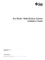
Sun Blade™ 6048 Modular System
Installation Guide
Sun Microsystems, Inc.
www.sun.com
Part No. 820-2312-10
October 2007, Revision A
Submit comments about this document to: http://www.sun.com/hwdocs/feedback
Copyright © 2007 Sun Microsystems, Inc., 4150 Network Circle, Santa Clara, California 95054, U.S.A. All rights reserved.
U.S. Government Rights - Commercial software. Government users are subject to the Sun Microsystems, Inc. standard license agreement and
applicable provisions of the FAR and its supplements.
Use is subject to license terms.
This distribution may include materials developed by third parties.
Parts of the product may be derived from Berkeley BSD systems, licensed from the University of California. UNIX is a registered trademark in
the U.S. and in other countries, exclusively licensed through X/Open Company, Ltd.
Sun, Sun Microsystems, the Sun logo, Java, Solaris, Sun Blade 6048 Chassis, Sun Blade and Sun are trademarks or registered trademarks of Sun
Microsystems, Inc. in the U.S. and other countries.
This product is covered and controlled by U.S. Export Control laws and may be subject to the export or import laws in other countries. Nuclear,
missile, chemical biological weapons or nuclear maritime end uses or end users, whether direct or indirect, are strictly prohibited. Export or
reexport to countries subject to U.S. embargo or to entities identified on U.S. export exclusion lists, including, but not limited to, the denied
persons and specially designated nationals lists is strictly prohibited.
Copyright © 2007 Sun Microsystems, Inc., 4150 Network Circle, Santa Clara, California 95054, Etats-Unis. Tous droits réservés.
Droits du gouvernement des États-Unis - logiciel commercial. Les droits des utilisateur du gouvernement des États-Unis sont soumis aux
termes de la licence standard Sun Microsystems et aux conditions appliquées de la FAR et de ces compléments.
L’utilisation est soumise aux termes de la Licence.
Cette distribution peut inclure des éléments développés par des tiers .
Des parties de ce produit pourront être dérivées des systèmes Berkeley BSD licenciés par l’Université de Californie. UNIX est une marque
déposée aux Etats-Unis et dans d’autres pays et sous licence exclusive de X/Open Company, Ltd.
Sun, Sun Microsystems, le logo Sun, Java, Solaris, Sun Blade 6048 Chassis, Sun Blade et Sun sont des marques de fabrique ou des marques
déposées de Sun Microsystems, Inc. aux Etats-Unis et dans d’autres pays.
Ce produit est soumis à la législation américaine en matière de contrôle des exportations et peut être soumis à la règlementation en vigueur
dans d’autres pays dans le domaine des exportations et importations. Les utilisations finales, ou utilisateurs finaux, pour des armes
nucléaires,des missiles, des armes biologiques et chimiques ou du nucléaire maritime, directement ou indirectement, sont strictement
interdites. Les exportations ou réexportations vers les pays sous embargo américain, ou vers des entités figurant sur les listes d’exclusion
d’exportation américaines, y compris, mais de manière non exhaustive, la liste de personnes qui font objet d’un ordre de ne pas participer, d’une
façon directe ou indirecte, aux exportations des produits ou des services qui sont régis par la législation américaine en matière de contrôle des
exportations et la liste de ressortissants spécifiquement désignés, sont rigoureusement interdites.
Contents
1.
Preparing to Install the Sun Blade 6048 Modular System
System Overview
1
Installation Overview
4
Verifying the Packaging Contents
Avoiding Electrostatic Discharge
2.
3.
5
6
Installing Modules and Options Into the Chassis
▼
To Install Server Modules
▼
To Install NEMs
▼
To Install PCI EMs
What to Do Next
1
7
8
9
11
12
Attaching Cables and Devices to Modules and Powering On the System
Chassis 13
Attaching I/O Cables to Sun Blade 6048 Modules
14
▼
To Attach CMM Network and Serial Console Cables
▼
To Attach NEM Cables
▼
To Attach PCI EM Data Network Cables
▼
To Attach a Dongle Cable to a Server Module
▼
To Attach the Power Cables to the AC Power Interface
14
15
Powering On the System Shelf for the First Time
16
17
18
20
iii
What to Do Next
4.
21
Configuring the Sun Blade 6048 Modular System Management Network
What Is Integrated Lights Out Manager?
24
About the Preconfigured CMM ILOM Administrator Account
Establishing an Initial Connection to the CMM ILOM
Assigning IP Addresses for the First Time
Prerequisites
23
25
25
26
26
▼
To Use DHCP to Assign the CMM IP Addresses Initially
▼
To Assign a Static IP Address to a CMM
27
28
Communicating With the CMM ILOM Using the Management Network IP
Addresses 30
Changing the CMM ILOM Root Account Default Password
▼
To Change the Password Using the CLI
▼
To Change the Password Using the Web Interface
What to Do Next
iv
34
Sun Blade 6048 Modular System Installation Guide • October 2007
30
31
31
Preface
The Sun Blade 6048 Modular System Installation Guide provides detailed information
about installing and setting up the Sun Blade™ 6048 modular system for the first
time.
This guide is written for system installers who are familiar with rackmounting
systems and installing computer hardware, as well as for system administrators who
are experienced with installing and configuring various operating systems.
How This Book Is Organized
Chapter 1 contains information about preparing to install the Sun Blade 6048
modular system.
Chapter 2 describes how to install modules and options into the chassis.
Chapter 3 contains information about attaching cables and devices to the system and
powering on the chassis.
Chapter 4 provides information about initial configuration of the Sun Blade 6048
modular system management system.
v
Related Documentation
For a description of the document set for the Sun Blade 6048 modular system, see
the Where To Find Documentation sheet that is packed with your system and also
posted at the product's documentation site. See the following web site, then navigate
to your product.
http://docs.sun.com
Translated versions of some of these documents are available at the documentation
web site in French, Simplified Chinese, Traditional Chinese, Korean, and Japanese.
English documentation is revised more frequently and might be more up-to-date
than the translated documentation.
Documentation, Support, and Training
Sun Function
URL
Documentation
http://docs.sun.com
Support
http://www.sun.com/support/
Training
http://www.sun.com/training/
vi Sun Blade 6048 Modular System Installation Guide • October 2007
Typographic Conventions
Typeface*
Meaning
Examples
AaBbCc123
The names of commands, files,
and directories; on-screen
computer output
Edit your.login file.
Use ls -a to list all files.
% You have mail.
AaBbCc123
What you type, when contrasted
with onscreen computer output
% su
Password:
AaBbCc123
Book titles, new words or terms,
words to be emphasized.
Replace command-line variables
with real names or values.
Read Chapter 6 in the User’s Guide.
These are called class options.
You must be superuser to do this.
To delete a file, type rm filename.
* The settings on your browser might differ from these settings.
Sun Welcomes Your Comments
Sun is interested in improving its documentation and welcomes your comments and
suggestions. You can submit your comments by going to:
http://www.sun.com/hwdocs/feedback
Please include the title and part number of your document with your feedback:
Sun Blade 6048 Modular System Installation Guide, part number 820-2312-10.
Preface
vii
viii Sun Blade 6048 Modular System Installation Guide • October 2007
CHAPTER
1
Preparing to Install the Sun Blade
6048 Modular System
This chapter provides information about preparing to install the Sun Blade 6048
modular system. It includes the following topics:
■
“System Overview” on page 1
■
“Installation Overview” on page 4
■
“Verifying the Packaging Contents” on page 5
■
“Avoiding Electrostatic Discharge” on page 6
System Overview
The Sun Blade 6048 modular system chassis consists of four shelves, with the
following maximum configuration for each shelf:
■
12 server modules (sometimes known as blades or blade modules)
■
24 PCI ExpressModules (PCI EMs)
■
2 network express modules (NEMs)
■
2 power supplies
■
8 rear fan modules
■
1 chassis management module (CMM)
1
FIGURE 1-1 shows the front and rear views of a fully populated system.
FIGURE 1-1
Front and Rear Views of System Chassis
FIGURE 1-2 shows the components that are common to each of the four shelves within
a fully populated Sun Blade 6048 chassis.
2
Sun Blade 6048 Modular System Installation Guide • October 2007
FIGURE 1-2
Single Shelf Components
Power supplies
Front indicator
module (FIM)
Server modules (blades)
PCI ExpressModules (PCI EMs)
Chassis
management
module (CMM)
Network express
module (NEM)
Rear fans
Chapter 1
Preparing to Install the Sun Blade 6048 Modular System
3
Installation Overview
TABLE 1-1 describes the tasks that you need to complete to set up the Sun Blade 6048
modular system. Step 1 and 2 should be completed before you begin the procedures
shown in this document.
TABLE 1-1
Installation Task List
Step
Task
Where to Find Information
1
Prepare your site for system installation and review
safety documentation.
Site Planning Guide and
Safety and Compliance
Manual for Sun Blade 6000
and 6048 Modular Systems
2
Unpack the Sun Blade 6048 chassis.
Sun Blade 6048 Modular
System Unpacking Guide
3
Verify the contents of your ship kit.
“Verifying the Packaging
Contents” on page 5
4
Prepare your installation environment to avoid
electrostatic discharge.
“Avoiding Electrostatic
Discharge” on page 6
5
Install Sun Blade 6048 modules and options into the
system chassis, if necessary.
Chapter 2
6
Cable and power on the Sun Blade 6048 modular
system.
Chapter 3
7
Configure IP addresses to enable network
management.
Chapter 4
8
Configure or install blade system software.
Server module installation
documentation
The documentation in this table, with the exception of the server module
documentation, can be found at:
http://docs.sun.com/app/docs/prod/blade.6048mod
4
Sun Blade 6048 Modular System Installation Guide • October 2007
Verifying the Packaging Contents
All Sun Blade 6048 modular system base features are assembled at the factory and
shipped to you preinstalled within the system chassis. Optional features, such as the
server modules, network express modules (NEMs), and PCI ExpressModules (PCI
EMs) can be either preinstalled or shipped separately for installation. The following
table describes the contents of the chassis packaging.
TABLE 1-2
Contents of Chassis Ship Kit
Chassis Packaged Items
Description
Sun Blade 6048 chassis
The shipped Sun Blade 6048 chassis contains:
• 48 server module filler panels or server modules (blades)
• 8 NEM filler panels or up to 8 NEMs (up to 2 per 12 blades)
• 96 PCI EM filler panels or PCI EMs (24 per 12 blades)
• 4 installed chassis management modules (1 per 12 blades)
• 8 power supplies (2 per 12 blades)
• 32 redundant rear fan modules (8 per 12 blades)
• Front and rear system indicator lights
• Service card attached to the side of the chassis
• Sun Blade 6048 Modular System Unpacking Guide attached to
the outside of the packing carton
Accessory kit
The accessory kit contains the following documentation:
• Where to Find Sun Blade 6048 Modular System Documentation
• Sun Blade 6048 Modular System Setup Poster
• Sun Blade 6048 Modular System Installation Guide
• Dongle for server module I/O connection
• RJ45 to DB9 serial adapter for dongle
• Other safety and license documentation
Country kit
The country kit includes the Sun Blade 6048 modular system
power cords.
Additional options
• PCI ExpressModules (PCI EMs): The Sun Blade 6048 chassis
supports up to 96 installed PCI EMs (up to 2 PCI EMs per
server module or 24 per shelf).
• Network express modules (NEMs): The Sun Blade 6048
chassis supports up to 8 installed NEMs (up to 2 single-slot
or 1 dual-slot NEMs per shelf).
• Server modules (blades): The Sun Blade 6048 chassis
supports up to 48 server modules (up to 12 per shelf).
Chapter 1
Preparing to Install the Sun Blade 6048 Modular System
5
Avoiding Electrostatic Discharge
Before installing the Sun Blade 6048 modular system modules and options into the
system chassis, review the information this section.
Caution – Internal modules and options are electronic components that are
extremely sensitive to static electricity. Ordinary amounts of static from your clothes
or work environment can destroy components.
To prevent static damage whenever you are accessing any of the internal
components, you must:
■
■
6
Place static-sensitive components such as hard drives, server modules, server
module options, NEMs, and PCI EMs on an antistatic surface. The following
items can be used as an antistatic surface:
■
The bag used to ship the component
■
Sun Electronic Discharge (ESD) mat, Sun part number 250-1088 (available
through your Sun sales representative)
Use an antistatic wrist strap. Attach this wrist strap to your wrist, and ground the
other end of strap to the system chassis (sheet metal).
Sun Blade 6048 Modular System Installation Guide • October 2007
CHAPTER
2
Installing Modules and Options Into
the Chassis
This chapter describes how to perform new installations of modules and options in a
Sun Blade 6048 chassis. The instructions and illustrations in this chapter refer to
installing modules into one of the four shelves in the Sun Blade 6048 chassis. The
instructions for each shelf are identical.
Caution – To keep the system from becoming top-heavy, make sure to populate the
chassis from the bottom shelf up.
Topics covered in this section include:
■
“To Install Server Modules” on page 8
■
“To Install NEMs” on page 9
■
“To Install PCI EMs” on page 11
Note – This section does not provide instructions for replacing existing chassis
modules and options that are installed in a powered-on system. The instructions in
this chapter assume that the new system has not yet been powered on. For
information about replacing existing modules and options, see the Sun Blade 6048
Modular System Service Manual, 820-2863.
7
▼
To Install Server Modules
Each Sun Blade 6048 shelf supports up to 12 server modules.
To remove a filler panel from a slot and to install a server module into the
corresponding vacant slot:
1. In the front of the system chassis, locate the slot into which you want to install
the server module.
2. Remove the filler panel, if necessary.
Rotate the lower ejector lever on the filler panel downward, and pull the filler
panel out of the chassis.
FIGURE 2-1 shows the filler panel being removed from the chassis.
FIGURE 2-1
Removing a Filler Panel
l
Note – Other filler panel should remain in any unused slots.
3. Position the server module vertically so that the ejectors are on the right.
See FIGURE 2-2.
8
Sun Blade 6048 Modular System Installation Guide • October 2007
FIGURE 2-2
Inserting the Server Module into the Chassis
4. Push the server module into the slot until the server module stops.
5. Rotate the ejectors down until they snap into place.
The server module is now flush with the chassis, and the ejectors are locked.
6. For each remaining server module to be installed, repeat Step 1 through Step 5.
7. Close the door of the system after all server modules are installed.
Caution – To comply with legal limits for electromagnetic interference (EMI)
emissions, the front cabinet door must remain closed during normal operation of the
product. The door should be opened only temporarily for servicing operations.
▼
To Install NEMs
Each Sun Blade 6048 shelf can have zero, one, or two network express modules
(NEMs) installed.
The NEM module will occupy either one or two NEM slots, depending on the type
of NEM that you have. If the NEM occupies both NEM slots, so you can install only
one module. If the NEM occupies one slot, you can install either one or two NEMs.
FIGURE 2-3 shows how to install both a dual-slot and single-slot NEM.
Chapter 2
Installing Modules and Options Into the Chassis
9
FIGURE 2-3
Installing a NEM
1. Align the NEM with the vacant NEM slot.
Ensure that the RJ-45 port connectors of the NEM are facing toward you and the
ejectors are positioned at the top of the NEM.
2. Fully open the NEM ejector levers.
3. Slide the NEM into the vacant NEM chassis slot until you feel it stop.
In FIGURE 2-3 Panel 1a shows installation of a dual-slot NEM and Panel 1b shows
installation of a single-slot NEM.
4. Secure the NEM by closing the ejector levers.
5. If you want to install another single-slot NEM, repeat Step 1 through Step 4.
10
Sun Blade 6048 Modular System Installation Guide • October 2007
▼
To Install PCI EMs
Each Sun Blade 6048 shelf supports up to 24 PCI ExpressModules (PCI EMs). The
PCI EM slots are labeled PCI EM 0.0 to 11.1. FIGURE 2-4 shows how to install a
PCI EM.
FIGURE 2-4
Installing an PCI EM
1. Align the PCI EM with the vacant PCI EM slot.
Ensure that the indicator lights on the front panel of the PCI EM are facing
toward you and that the PCI EM ejector lever on the bottom is fully opened.
2. Slide the PCI EM into the vacant PCI EM chassis slot.
The ejector lever starts to pop up as the module engages with the system slot.
Chapter 2
Installing Modules and Options Into the Chassis
11
3. Complete the installation by closing the ejector lever to secure the PCI EM in
the chassis.
4. For each remaining PCI EM to be installed, repeat Step 1 through Step 3.
What to Do Next
After installing modules and options into each shelf of the Sun Blade 6048 chassis,
you are ready to connect the power cables and power on the system. See Chapter 3.
12
Sun Blade 6048 Modular System Installation Guide • October 2007
CHAPTER
3
Attaching Cables and Devices to
Modules and Powering On the
System Chassis
This chapter describes how to connect the AC power cables, management network
cables, and data network cables to the appropriate chassis modules. Finally, this
chapter tells you how to power on the system chassis for the first time.
Note – The instructions and illustrations in this chapter refer to cabling and
powering on each of the four shelves in the Sun Blade 6048 chassis. The instructions
for each shelf are identical.
Topics covered in this chapter include:
■
“Attaching I/O Cables to Sun Blade 6048 Modules” on page 14
■
“Powering On the System Shelf for the First Time” on page 20
■
“What to Do Next” on page 21
13
Attaching I/O Cables to Sun Blade 6048
Modules
This section covers the following topics:
▼
■
“To Attach CMM Network and Serial Console Cables” on page 14
■
“To Attach NEM Cables” on page 15
■
“To Attach PCI EM Data Network Cables” on page 16
■
“To Attach a Dongle Cable to a Server Module” on page 17
■
“To Attach the Power Cables to the AC Power Interface” on page 18
To Attach CMM Network and Serial Console
Cables
Each chassis contains a chassis monitoring module (CMM) with two Ethernet (NET
MGT) ports and one serial management (SER MGT) port available. This section
provides instructions for attaching a local area network cable and a serial console
cable to the management ports on the rear panel of a CMM.
Note – If you want to communicate directly with a server module, you can connect
a serial console to the front panel of the server module by using the dongle cable
that is included with your Sun Blade 6048 chassis. See the documentation for your
server module system for further information.
1. Locate an Ethernet network management cable and a serial console cable.
14
Sun Blade 6048 Modular System Installation Guide • October 2007
FIGURE 3-1
CMM NET MGT Ports
NET MGT port 1
NET MGT port 0
SER MGT port
2. Attach the serial console cable to the SER MGT port on the rear panel of the
CMM, and plug the other end of the cable to the serial terminal.
3. Plug the Ethernet cable into NET MGT 0 port on the CMM, and plug the other
end of the Ethernet cable to your local area network.
Note – The NET MGT 1 port is disabled by default. You can enable port 1 through
the ILOM. See the Sun Blade 6048 Modular System Service Manual, 820-2863, for more
information.
▼
To Attach NEM Cables
This section provides instructions for attaching cables to the network express
modules (NEMs).
Each shelf in the Sun Blade 6048 chassis provides up to two NEM slots, labeled NEM
0–1 with 0 being the bottom NEM slot and 1 being the top NEM slot. Dual-slot
NEMs occupy both slots for a single NEM, and single-slot NEMs occupy one of the
slots.
FIGURE 3-2 shows the correspondence between NEM ports and blades on a Gigabit
Ethernet NEM.
Note – For details on the Infiniband NEM operation, refer to the Sun Blade 6048
Switched InfiniBand Network Express Module User’s Guide, 820-2189.
Chapter 3
Attaching Cables and Devices to Modules and Powering On the System Chassis
15
FIGURE 3-2
NEM to Server Module Correspondence
To cable a NEM:
1. Locate the cables needed for your configuration.
2. Connect the cable to the appropriate port on the NEM.
3. Attach the other end of the data cable to the appropriate data source.
▼
To Attach PCI EM Data Network Cables
This section provides instructions for attaching data network cables to the PCI
ExpressModule (PCI EM).
For each PCI EM installed, there are two external data ports provided. Each Sun
Blade 6048 shelf provides 24 PCI EM slots, with 2 PCI EM slots assigned to each
server module. The PCI EM slots are numbered PCI EM 0.0 to 11.1 right to left as
viewed from the rear of the chassis.
FIGURE 3-3 shows how the NEMs correspond to the blades installed in the system.
16
Sun Blade 6048 Modular System Installation Guide • October 2007
FIGURE 3-3
Server Module to PCI EM Correspondence
Note – The following procedure assumes that you have recorded the MAC address
for each PCI EM data port. The PCI EM port MAC addresses are printed on the PCI
EM board.
To cable a PCI EM:
1. Locate the cables needed for your configuration.
2. Plug the data network cable into the appropriate RJ-45 data port.
3. Attach the other end of the data network cable to the appropriate data source.
▼
To Attach a Dongle Cable to a Server Module
In a fully populated shelf, there are 12 server modules. A dongle cable is included
with the Sun Blade 6048 chassis to provide USB, serial, and VGA I/O connections
for the server modules. See FIGURE 3-4.
Chapter 3
Attaching Cables and Devices to Modules and Powering On the System Chassis
17
FIGURE 3-4
Dongle Cable for Server Module Connections
See the server module documentation for information about connectors for each
server module.
▼
To Attach the Power Cables to the AC Power
Interface
The Sun Blade 6048 AC power interface supplies main power to the modules in the
system chassis. Each Sun Blade 6048 shelf includes two power supply modules that
provide six power inlets. FIGURE 3-5 shows the AC power inlets.
Note – You should be familiar with the Sun Blade 6048 modular system power
requirements prior to attaching the power cables to a customer-supplied power
distribution unit (PDU). For more information about system power requirements,
see the Sun Blade 6048 Modular System Site Planning Guide, 820-0426.
To cable the power supplies:
1. Make sure that the front cabinet door is closed.
18
Sun Blade 6048 Modular System Installation Guide • October 2007
Caution – To comply with legal limits for electromagnetic interference (EMI)
emissions, the front cabinet door must remain closed during normal operation of the
product. The door should be opened only temporarily for servicing operations.
2. Locate six of the power cables shipped with the system.
3. Locate the AC inlets on the power interface on the rear of the chassis.
FIGURE 3-5
AC Power Inlets
PS1- PS1AC2 AC1
PS1AC0
PS0AC2
PS0- PS0AC1 AC0
4. Open the metal retention clips for each power inlet.
5. In the rear of the chassis, plug six power cables into slot positions PS0-AC0,
PS0-AC1, PS0-AC2, PS1-AC0, PS1-AC1, and PS1-AC2.
6. Secure the cables to the connector with the metal retention clip.
7. Plug the other end of the power cables into the power distribution unit (PDU).
Main power is automatically distributed to the system chassis and the OK power
LEDs on the CMM and front indicator module (FIM) flash.
Note – By default, the Power-on option is enabled in the CMM Integrated Lights
Out Manager (ILOM). If you disable this option, only standby power is applied to
the chassis monitoring module in the system chassis when you plug in the AC
power cords.
Chapter 3
Attaching Cables and Devices to Modules and Powering On the System Chassis
19
Powering On the System Shelf for the
First Time
Main power is automatically supplied to the system shelf as soon as the power
supplies receive power. When the system shelf is powered up, main power is
applied to all installed modules: CMM, NEMs, server modules, and PCI EMs.
Note – This section describes the 8400 W power supply. Other power supply
configurations might be available. For further information, refer to the product
pages at http://sun.com/blades
This section describes how to ensure that the system chassis is powered on and the
server modules are powered on.
To ensure that the system shelf is powered up:
1. Make sure that all six of the AC power cables are attached from the power
interface module to a power source.
For details, see “To Attach the Power Cables to the AC Power Interface” on
page 18.
The system chassis automatically applies main power to all modules in the
chassis after power is provided to the power supplies.
2. Make sure that main power is applied to the system shelf.
The OK power LED is a solid green light. There are OK power LEDs located on
the front and rear of the chassis, as well as power supply LEDs shown in
FIGURE 3-6.
FIGURE 3-6
Front Power LEDs
OK LED
Front
power
LED
AC-2 LED
AC-1 LED
AC-0 LED
20
Sun Blade 6048 Modular System Installation Guide • October 2007
FIGURE 3-7
Rear Power LEDs
Rear
power
LED
CMM
power
LED
Note – See the server documentation for power-on information for the server
modules.
What to Do Next
After attaching cables to I/O modules, attaching local devices to the server modules,
and powering on the system, you are ready to configure the CMM and server
module management network. See Chapter 4.
Chapter 3
Attaching Cables and Devices to Modules and Powering On the System Chassis
21
22
Sun Blade 6048 Modular System Installation Guide • October 2007
CHAPTER
4
Configuring the Sun Blade 6048
Modular System Management
Network
This chapter describes how to configure the chassis monitoring module (CMM) with
an IP address using the Sun Integrated Lights Out Manager (ILOM). Specifically, it
walks you through the steps of establishing a connection with a CMM using ILOM.
It then describes how to configure the CMM with static or dynamic (DHCP) IP
addresses.
Note – The instructions and illustrations in this chapter refer to installing modules
into one of the four subassemblies in the Sun Blade 6048 chassis. The instructions for
each shelf are identical.
Topics discussed in this chapter include:
■
“What Is Integrated Lights Out Manager?” on page 24
■
“Establishing an Initial Connection to the CMM ILOM” on page 25
■
“Changing the CMM ILOM Root Account Default Password” on page 30
23
What Is Integrated Lights Out Manager?
The Integrated Lights Out Manager (ILOM) is a built-in system management tool
that enables you to monitor and manage the components installed in a Sun Blade
6048 shelf. The ILOM is accessed through the CMM service processor. For instance,
in the CMM ILOM, you can configure network information, view and edit hardware
configurations, monitor vital system information, and manage user accounts.
Note – The term CMM ILOM in this document refers to the ILOM that runs on the
Sun Blade 6048 shelf CMM service processor. For information about server
management systems specific to the server modules installed in the Sun Blade 6048
chassis, see the server module documentation. Some server modules that are
installed in the Sun Blade 6048 shelf might use a different management software.
The CMM ILOM is accessible through command-line interfaces (CLI), the ILOM web
interface, and IPMI.
Any user with a valid user account can access the CMM ILOM. The first time you
access the CMM ILOM, you need to use the preconfigured ILOM administrator
account.
For more information about the tasks that you can perform in the CMM ILOM, see
the Sun Integrated Lights Out Manager 2.0 User’s Guide, 820-1188. For more
information about the preconfigured ILOM administrator account, see “About the
Preconfigured CMM ILOM Administrator Account” on page 25.
24
Sun Blade 6048 Modular System Installation Guide • October 2007
About the Preconfigured CMM ILOM
Administrator Account
Each Sun Blade 6048 shelf includes one preconfigured CMM ILOM administrator
account with the following log in:
User name: root
Password: changeme
You cannot change the preconfigured administrator account (root) other than
changing its default password. This account offers built-in administrative privileges
(read and write access) to all CMM ILOM functions, features, and commands.
The first time you access ILOM at the CMM level or server module level you need to
log in as root with the default password changeme. After you have logged in to the
CMM ILOM and established network connectivity to the system, change the
password associated with the ILOM root account to prevent your system from
unauthorized access.
For more information about resetting the ILOM root account password, see
“Changing the CMM ILOM Root Account Default Password” on page 30.
Establishing an Initial Connection to the
CMM ILOM
To set up CMM and server modules with initial network configuration information,
you must establish a connection through ILOM to the CMM.
Until the CMM has an IP address assigned to it, you must use a serial connection to
communicate with the CMM. After establishing a serial connection to the CMM, you
can choose to configure the CMM and server modules with static or DHCP IP
addresses.
This section includes the following topics:
■
“Assigning IP Addresses for the First Time” on page 26
■
“Communicating With the CMM ILOM Using the Management Network IP
Addresses” on page 30
Chapter 4
Configuring the Sun Blade 6048 Modular System Management Network
25
Assigning IP Addresses for the First Time
This section includes the following topics:
■
“To Use DHCP to Assign the CMM IP Addresses Initially” on page 27
■
“To Assign a Static IP Address to a CMM” on page 28
Prerequisites
Before assigning IP addresses, ensure that you have completed the following
installation tasks:
■
Unpacked and completed the hardware and cabling setup of the Sun Blade 6048
modular system. For details, see Chapter 1, Chapter 2, and Chapter 3.
■
Attached an Ethernet cable to the NET MGT port on the rear panel of the CMM of
the Sun Blade 6048 shelf. For details, see “To Attach CMM Network and Serial
Console Cables” on page 14.
■
Established console access to the CMM (or server module) through a serial
connection. For details, see “To Attach CMM Network and Serial Console Cables”
on page 14.
■
Configured serial settings:
■
■
8N1: eight data bits, no parity, one stop bit
■
9600 baud
■
Disable hardware flow control (CTS/RTS)
■
Disable software flow control (XON/XOFF)
Ensured that the main power was applied to the chassis and the server modules.
For details, see “Powering On the System Shelf for the First Time” on page 20.
Note – If you intend to have DHCP IP addresses assigned, you need to have an
established DHCP server on the same local network as the Sun Blade 6048 modular
system. Setting up a DHCP server is out of the scope of this guide. See the
documentation supplied with the DHCP server software.
26
Sun Blade 6048 Modular System Installation Guide • October 2007
▼
To Use DHCP to Assign the CMM IP Addresses
Initially
When you first apply power, the CMM ILOM broadcasts a DHCP request for an IP
address. If a DHCP server receives this request, it will supply an address and other
network information. If server modules are powered up at the same time, they also
broadcast the DHCP request and receive individual IP addresses.
Note – Refer to the server module documentation for information about assigning a
DHCP address to a server module SP.
Follow these instructions when using DHCP to assign IP addresses:
1. Make sure that your DHCP server is configured to accept new media access
control (MAC) addresses. Refer to the documentation supplied with your
DHCP server software.
2. Make sure that the Ethernet cable is plugged into the NET MGT port on the
active CMM.
■
As long as the CMM ILOM was not configured previously with a static IP, the
CMM ILOM automatically broadcasts a DHCPDISCOVER packet with the ID
of its CMM MAC address and server module MAC addresses.
■
The DHCP server on your network returns the DHCPOFFER packet containing
the IP address and other information. The CMM then manages its “lease” of IP
addresses assigned by the DHCP server.
3. To obtain the DHCP IP addresses assigned to the CMM and server module SPs
via the CMM serial connection:
a. Using a serial console attached to the rear panel of the CMM, log in to the
CMM ILOM as the administrator.
The preconfigured administrator username is root and its default password
changeme.
b. To set the working directory for the active CMM, type:
cd /CMM/network
c. To view the active CMM IP address, type:
show
Note – You can also view the IP addresses via the DHCP server logs. Refer to the
DHCP server documentation for details.
Chapter 4
Configuring the Sun Blade 6048 Modular System Management Network
27
▼
To Assign a Static IP Address to a CMM
If you want to use static addresses instead of the dynamic addresses provided by
your DHCP server, you can assign the static IP address at the following times:
■
Before attaching a LAN cable to the NET MGT port of the CMM.
■
After the modules have been assigned an DHCP IP address. You can change the
DHCP assigned address to a static IP address.
Follow these instructions when assigning a static IP address to a CMM through a
serial connection:
1. Verify that your serial connection to the active CMM is operational.
For information about attaching a serial console to a CMM, see “To Attach CMM
Network and Serial Console Cables” on page 14.
2. Log in to the CMM ILOM as an administrator by entering an administrator
user name (default: root) and password (default: changme), and then press
Enter.
The default prompt appears (->), and the system is ready for you to run the CLI
commands to establish network settings.
3. To set a static IP address on the CMM through ILOM using the CLI, type the
following command to set the working directory:
cd /CMM/network
28
Sun Blade 6048 Modular System Installation Guide • October 2007
4. Use the following commands to specify the IP, netmask, and gateway
addresses.
Command
Description and Example
set pendingipaddress=
Type this command followed by the static IP address that
you want to assign to the CMM.
Example: Typing set pendingipaddress=
129.144.82.26 tells ILOM to assign 129.144.82.26
as the CMM IP address.
set pendingipnetmask=
Type this command followed by the static netmask
address that you want to assign to the CMM.
Example: Typing set pendingipnetmask=
255.255.255.0 tells ILOM to assign 255.255.255.0
as the CMM netmask address.
set pendingipgateway=
Type this command followed by the static gateway
address that you want to assign to the CMM.
Example:
Typing set pendingipgateway=129.144.82.254
tells ILOM to assign 129.144.82.254 as the CMM
gateway address.
set pendingipdiscovery=
Type the following command to tell ILOM whether you
want to set a static IP address.
set pendingipdiscovery=static
set commitpending=true
Type this command (true) to assign the network settings
specified.
Example:
set pendingipaddress=129.144.82.26
set pendingipnetmask=255.255.255.0
set pendingipgateway=129.144.82.254
set commitpending=true
Chapter 4
Configuring the Sun Blade 6048 Modular System Management Network
29
Communicating With the CMM ILOM Using the
Management Network IP Addresses
After the CMM has been assigned IP addresses, use these IP addresses to
communicate with the CMM ILOM. Specifically, the management network IP
address is the IP address assigned to the service processor of the CMM.
In addition to the management network IP addresses, you will also have IP
addresses associated with the data network. The data network IP addresses are
configured after you install the host operating system on a server module. It is
important to distinguish the data network IP addresses from the management
network IP addresses since they serve different purposes.
You need to specify the IP address of the CMM when you want to perform
management operations at the chassis level. To perform management operations at a
server module level, you need to specify the IP addresses of the server module
service processor.
For further information about specifying IP addresses for the server modules, refer
to the server module documentation. For more information about management tasks
that you can perform at the chassis level, see the Sun Integrated Lights Out Manager
2.0 User’s Guide, 820-1188.
Changing the CMM ILOM Root Account
Default Password
The following procedures describe how to change the default password for the
ILOM using the CLI or the ILOM web interface.
For information about creating new user accounts and assigning a role (privileges)
to a user account, see the Sun Integrated Lights Out Manager 2.0 User’s Guide,
820-1188, and the documentation for the server modules that you have installed.
30
Sun Blade 6048 Modular System Installation Guide • October 2007
▼
To Change the Password Using the CLI
To change the changeme password:
1. Using a serial console attached to the rear panel of the CMM, log in to the
CMM ILOM as the administrator at the login prompt.
The preconfigured administrator username is root and its default password
changeme.
2. Change the password for the CMM by typing:
set /CMM/users/root password=password
password: The new password that you want to assign.
3. Repeat Steps 1 and 2 for each CMM as necessary.
▼
To Change the Password Using the Web
Interface
Follow these steps to change the password for the root account:
1. Open a web browser, and type the IP address of the CMM.
The Login page for the ILOM web interface appears.
2. In the ILOM Login page, do the following:
a. Type the default user name (root) and password (changeme).
b. Click Log In.
The ILOM web interface appears.
3. Click CMM in the left navigation pane.
4. In the ILOM web interface, choose User Management --> User Accounts.
The User Account Settings page appears.
Chapter 4
Configuring the Sun Blade 6048 Modular System Management Network
31
FIGURE 4-1
User Account Settings Page
5. In the User Account Settings page, select the radio button next to root, then
click Edit.
A security message appears.
32
Sun Blade 6048 Modular System Installation Guide • October 2007
6. Click OK to continue. The User Account Password dialog appears.
FIGURE 4-2
User Account Password Dialog
7. In the User Account password dialog, do the following:
a. Select Change.
b. In the New Password field, type the new password.
c. In the Confirm Password field, type the new password again.
d. Click Save.
The new password is activated for the root Administrator account.
8. If necessary, use this procedure to change the password for each installed
CMM.
Chapter 4
Configuring the Sun Blade 6048 Modular System Management Network
33
What to Do Next
After configuring network information for each Sun Blade 6048 shelf, you are ready
to set up the server modules with an operating system. For details, see the
documentation for the server modules that are installed in the Sun Blade 6048
modular system.
34
Sun Blade 6048 Modular System Installation Guide • October 2007
Index
A
I
AC power interface, 18 to 19
ILOM, See Integrated Lights Out Manager
installation
chassis monitoring modules (CMMs), 12
network express modules (NEMs), 10
PCI ExpressModules (PCI EMs), 12
Integrated Lights Out Manager (ILOM), 24 to 30
preconfigured administrator account
logging in, 25
resetting the root password, 30
set command, CMM, table of options, 29
system communication through assigned
network IP addresses, 30
IP address assignment, initial, 25 to 30
for DHCP assigned addresses, 27
prerequisites, 26
C
chassis
adding modules and options
chassis monitoring modules (CMM), 12
network express modules (NEMs), 10
PCI ExpressModules (PCI EMs), 12
initial power-on, 20
module connections
network express modules (NEMs), 15
PCI ExpressModules (PCI EMs), 16
packaging and unpacking, 5
power supply connections, 18 to 19
chassis management module (CMM)
configuring IP addresses
DHCP assignment, 27
prerequisites, 26
set command (ILOM), table of options, 29
connecting to a local area network, 14
D
documentation, related, vi
E
N
network express modules (NEMs)
chassis slots, 15
connecting to a local area network, 15
installing, 10
server module connections, 15
specifications, 5
network information, configuring, See Integrated
Lights Out Manager (ILOM)
electrostatic discharge, avoiding, 6
P
H
hardware configurations, managing, See Integrated
Lights Out Manager (ILOM)
PCI ExpressModules (PCI EMs)
chassis slots, 16
connecting to a local area network, 16
data network ports, 16
35
installing, 12
server module connections, 16
specifications, 5
power cables, attaching to the AC power
interface, 18 to 19
power-on, initial, 20
R
related documentation, vi
root account password, 31
S
server modules
configuring DHCP IP addresses, 27
network express modules (NEMs), connecting
to, 15
PCI ExpressModules (PCI EMs), connecting
to, 16
shipping (what you should receive), 5
support information, vi
T
third-party Web sites, vii
training information, vi
typographic conventions, vii
36
Sun Blade 6048 Modular System Installation Guide • October 2007