1
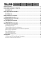
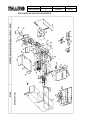
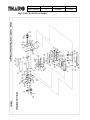
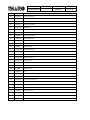
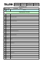
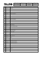
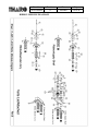
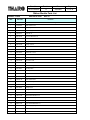
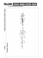
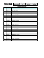
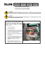
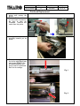
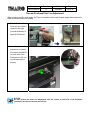
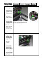
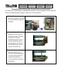
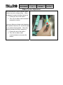
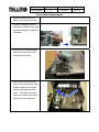
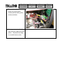
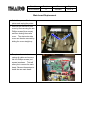
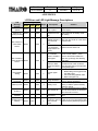
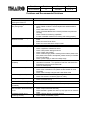
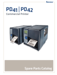
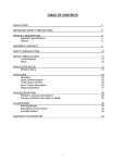
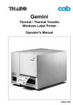
Doc. No. 730-013400-00 Revision A Date 2004/8/27 Page 1 of 33 Service Manual H-426 / H-434 Thermal Transfer Printer Doc. No. 730-013400-00 Revision A Date 2004/8/27 Page 2 of 33 SPECIFICATIONS..........................................................................................................3 EXPLODED DIAGRAM OF PRINTER ...........................................................................4 H-426 Parts List .......................................................................................................................................... 5 H-434 Parts List .......................................................................................................................................... 8 PRINT MECHANISM ASSEMBLY ............................................................................... 11 H-426 Parts List ........................................................................................................................................ 12 H-434 Parts List ........................................................................................................................................ 14 RIBBON MODULE DIAGRAM.....................................................................................16 Ribbon Module Parts List ...................................................................................................................... 17 REWINDER MODULE DIAGRAM ...............................................................................18 Rewinder Parts List ................................................................................................................................. 19 CUTTER MODULE DIAGRAM ....................................................................................20 Cutter Parts List ........................................................................................................................................ 21 MAINTENANCE PROCEDURES.................................................................................22 Cleaning the Thermal Printhead ........................................................................................................... 22 Printhead Replacement ........................................................................................................................... 23 Thermal Printhead Print Line Adjustment ......................................................................................... 24 Thermal Printhead Spring Box Position/Pressure Adjustment ..................................................... 26 Ribbon Tension Adjustment .................................................................................................................. 27 Drive Roller Replacement...................................................................................................................... 28 Main board Replacement ....................................................................................................................... 30 Power Supply Replacement ................................................................................................................... 31 APPENDIXES ..............................................................................................................32 LCD Error and LED Light Message Descriptions........................................................................... 32 Problems and Recommended Solutions ............................................................................................. 33 Doc. No. 730-013400-00 Revision A Date 2004/8/27 Page 3 of 33 SPECIFICATIONS Model Resolution Print Mode Printer CPU Sensor Location Sensor Type Sensor Detection Print Speed Print Length Print Width Media Ribbon Printer Language Software Resident Fonts Downloadable Fonts Image Handling Bar Codes Interfaces Serial Interface Transmission Speed Memory LCD Display Power Real-Time Clock Environment Humidity Agency Listings Printer Dimensions Options THARO H–426 THARO H-434 8 dots/mm (203dpi) 12 dots/mm (300dpi) Thermal Transfer/Direct Thermal Thermal Transfer/Direct Thermal 16 Bit Processor Moveable, left aligned Reflective, Transmissive Type: Label gap and black mark sensing Detection: Label length auto sensing and/or program command setting 50.8mm (2”)/sec ~ 152.4mm (6”)/sec 50.8mm (2”)/sec ~ 101.6mm (4”)/sec 12mm (0.47”) ~ 1270mm (50”) 12mm (0.47”) ~ 558.8mm (22”) 25mm (1”) ~ 104mm (4.09”) 25mm (1”) ~ 105mm (4.13”) Label Roll: Max. 203mm (8”) O.D. Core Diameter: 38.1mm (1.6”) ~ 76.2mm (3”) Width: 25.0mm (1”) ~ 118.0mm (4.65”) Thickness: 0.06mm (0.002”) ~ 0.25mm (0.009”) Material: Thermal Transfer ribbons (wax, resin and wax/resin) Type: Ink inside or ink outside Length: 450m (1471’) Width: 30mm (1.18”) ~ 110mm (4.33”) Inner Core Diameter: 25.4mm (1”) Ribbon Roll Diameter: 75mm (2.95”) TPL (Tharo Programming Language) ® Application: EASYLABEL Start Driver: Microsoft Windows 95, 98, ME, NT 4, 2000 and XP 9 resident alphanumeric fonts (including OCR A & B) that are available in 4 orientations (0°, 90°, 180°, 270°), 8-point sizes (6, 8, 10, 12, 14, 18, 24, 30), and are expandable 8 times horizontally and vertically. Windows Bit-map fonts and Asian fonts are downloadable. Windows fonts in 4 orientations (0°, 90°, 180°, 270°). Asian fonts in 8 orientations. BMP and PCX Code 39, Code 93, Code 128 (subset A, B, C), UCC 128, UPC A, UPC E, UPC 2 & 5 digit add on, I 2 of 5, EAN 8, EAN 13, EAN 2 & 5 digit add on, Codabar, Postnet, EAN 128, DUN 14, MaxiCode, PDF417, and DataMatrix Serial, Parallel, USB, PS/2 keyboard Baud rate 300 ~ 38400, XON/XOFF, DSR/DTR Built-In: 2MB Flash, 2MB DRAM Optional: An additional 2MB of Flash Backlit Graphic LCD Display Three bi-color LED lamps: Power, Ready, Error Three Control keys: Feed, Pause, Cancel 110/240VAC, 50/60 Hz Time and Date stamp Operation: 5°C to 40°C (40°F to 104°F) Storage: -20°C to 50°C (-40°F to 122°F) Operation: 30-85%, non-condensing. Free air. Storage: 10-90%, non-condensing. Free air. CE, CUL, FCC Class A Length: 454.58mm (17.9”) Height: 277.30mm (10.92”) Width: 275.55mm (10.85”) Weight: 13Kg (28.7lbs) Cutter with Tray Internal Rewind 2MB Flash memory module Stand-alone keyboard Specifications are subject to change without notice. Doc. No. 730-013400-00 Revision A EXPLODED DIAGRAM OF PRINTER Date 2004/8/27 Page 4 of 33 Doc. No. 730-013400-00 Revision A Date 2004/8/27 H-426 Parts List MODEL: H-426 Item 08-24-2004 REV: A Tharo No. Part Name H-426 1 710-029300-00 Base Plate 2 703-029900-00 Rubber Foot 3 141-020047-90 MAIN PCB Assembly H-426 4 710-029400-02 Printhead Pressure Shaft 5 710-028200-00 Power Bracket 6 141-020036-90 Switching Power Supply Assembly (UPS110-1241-1) 7 710-030200-01 Left Cover 8 710-028800-00 Paper Roll Plate 9 710-028700-01 Label Roll Bar 10 700-039401-00 Label Adjust Lever 11 712-029700-00 Label Adjust Lever Spring 13 700-032201-00 Ribbon Position Lever 14 710-029500-01 Back Cover 15 141-020040-90 Power Switch Assembly 16 601-060009-05 Power Cable-MAIN PCB 17 601-000021-00 RS232 18 701-001500-01 22T Gear (Double Hub) 20 705-001700-00 Acrylic Plate 21 710-039700-00 Right Cover 22 705-002300-00 LOGO 23 700-031800-01 Top Right Panel 24 700-031900-02 Bottom Right Panel 25 700-031700-02 Left Panel 26 700-041000-00 LCD Cover 27 141-020037-95 LCD PCB Assembly 28 601-260006-00 LCD Cable - Main PCB 29 160-000106-00 RIBBON OUT PCB 30 700-035500-00 Cushion Ø4*9*1.5 31 820-530080-25 Screw M3*8 32 801-440100-14 Screw M4*10(SW+W) 33 801-230452-11 Flat Head Screw M3*4.5 34 840-000002-00 Boss 3*10 35 801-630060-17 Hex Screw M3*6 Page 5 of 33 Doc. No. 730-013400-00 Revision A 36 851-821615-00 Metal Washer Ø8.2*1.5t 37 141-020024-95 Ribbon Assembly 38 131-00H426-00 Mechanism Assembly 39 462-030012-00 Stepping Motor 40 701-001900-00 Idle Poly 41 711-029200-00 Poly Core 42 710-028300-00 Poly Bracket 43 712-027300-00 Idle Ploy Spring 44 703-027700-00 Belt 100MXL 45 858-400805-00 Washer Ø4*Ø8*0.5t 46 703-028800-00 Wire Clip(WL-1) 47 710-028500-00 Motor Bracket 48 710-034100-00 Liner Rewind Cover 49 801-430060-15 Screw M3*6+SW 50 855-300706-00 E Ring Ø3 51 855-400906-00 E Ring Ø4 52 712-027200-00 Ribbon Rewind Spring 53 700-036000-01 Stripper Box 54 700-036700-00 Cushion 20*20*5t 55 700-036600-00 Mylar 13*9.5*0.25t 56 703-027500-00 Plastic Screw SR2.6-3.2 58 730-012300-00 Ribbon & Label Instruction Label 59 731-011700-01 Ribbon Position Label 60 801-940060-19 Screw M4*6+Tooth Washer 61 701-002900-00 22T Gear (Single Hub) 62 160-000114-00 Stripper Sensor PCB 63 601-020023-00 2 Pin Cable-Rewinder 64 601-050019-00 5 Pin Cable-Cutter 65 701-001200-00 64T (ID 4) Gear 66 701-002500-00 40/36 Tooth Gear 67 703-027800-02 Belt 140MXL 68 703-029000-00 Hand Screw M4*6*Ø10 69 820-417050-15 Screw M1.7*5 70 855-501106-00 E Ring Ø5 71 858-602905-00 Washer Ø6*Ø29*0.5t 72 705-002000-00 LCD Cover Plate 73 700-040900-00 Mylar Piece 74 700-039501-00 Label Adjust Lever Core Date 2004/8/27 Page 6 of 33 Doc. No. 730-013400-00 75 713-020500-00 Spring Twig Ø2.5*18L 76 856-301003-00 E-Ring Ø3*Ø10*0.3t(SPN-3) 77 841-030551-20 Nut/BK/M3*0.5 78 710-048100-00 Ethernet Socket Cover Revision A Date 2004/8/27 Page 7 of 33 Doc. No. 730-013400-00 Revision A H-434 Parts List Item Tharo No. Part Name H-434 1 710-029300-00 Base Plate 2 703-029900-00 Rubber Foot 3 141-020048-90 MAIN PCB Assembly 4 710-029400-02 Middle Wall Plate 5 710-028200-00 Power Bracket 6 141-020036-90 Switching Power Supply Assembly 7 710-030200-01 Left Cover 8 710-028800-00 Paper Roll Plate 9 710-028700-01 Label Roll Bar 10 700-039401-00 Label Adjust Lever 11 712-029700-00 Label Adjust Lever Spring 13 700-032201-00 Ribbon Position Lever 14 710-029500-01 Back Cover 15 141-020036-90 Power Switch Assembly 16 601-060009-05 Power Cable-Main PCB 17 601-000021-00 RS232 18 701-001500-01 22T Gear (Double Hub) 20 705-001700-00 Acrylic Plate 21 710-039700-00 Right Cover 22 705-002300-00 LOGO 23 700-031800-01 Top Right Panel 24 700-031900-02 Bottom Right Panel 25 700-031700-02 Left Panel 26 700-041000-00 LCD Cover 27 141-020037-95 LCD PCB Assembly 28 601-260006-00 LCD Cable-Main PCB 29 160-000106-00 RIBBON OUT PCB 30 700-035500-00 Cushion Ø4*9*1.5 31 820-530080-25 Screw M3*8 32 801-440100-14 M4*10 33 801-230452-11 Flat Head Screw M3*4.5 34 840-000002-00 Boss 3*10 35 801-630060-17 Hex Screw M3*6 Date 2004/8/27 Page 8 of 33 Doc. No. 730-013400-00 36 851-821615-00 Metal Washer Ø8.2*16*1.5t 37 141-000024-20 Ribbon Assembly 38 131-00H434-00 Mechanism Assembly 39 462-030012-00 Stepping Motor 40 701-001900-00 Idle Poly 41 711-029200-00 Poly Core 42 710-028300-00 Poly Bracket 43 712-027300-00 Idle Poly Spring 44 703-027700-01 Belt 100MXL 45 858-400-805-00 Washer Ø4*Ø8*0.5t 46 703-028800-00 Wire Clip (WL-1) 47 710-028500-00 Motor Bracket 48 710-034100-00 Rewinder Wall Plate 49 801-430060-15 Screw M3*6+SW 50 855-300706-00 E Ring Ø3 51 855-400906-00 E Ring Ø4 52 712-027200-00 Ribbon Rewind Spring 53 700-036000-01 Stripper Box 54 700-036700-00 Cushion 20*20*5t 55 700-036600-00 Mylar Piece 13*9.5*0.25t 56 703-027500-00 Plastic Screw SR2.6-3.2 58 730-012300-02 Ribbon & Label Instruction Label 59 731-011700-00 Ribbon Position Label 60 801-940060-19 Screw M4*6+Tooth Washer 61 701-002900-00 22T(Single Hub) 62 160-000114-00 Stripper Sensor PCB 63 601-020023-00 2 Pin Cable Rewinder 64 601-050019-00 5Pin Cable-Cutter 65 701-001200-00 64T (ID 4) Gear 66 701-002500-00 40/36 Tooth Gear 67 703-027800-02 Belt 140MXL 68 703-029000-00 Hand Screw M4*6*Ø10 69 820-417051-15 Screw M1.7*5 70 855-501106-00 E Ring Ø5 71 858-602905-00 Washer Ø6*Ø29*0.5t 72 705-002000-00 LCD Cover Plate 73 700-040900-00 Mylar Piece 74 700-039501-00 Label Adjust Lever Core Revision A Date 2004/8/27 Page 9 of 33 Doc. No. 730-013400-00 75 713-020500-00 Spring Twig Ø2.5*18L 76 856-301003-00 E-Ring Ø3*Ø10*0.3t(SPN-3) 77 841-030551-20 Nut/BK/M3*0.5 78 710-048100-00 Ethernet Socket Cover Revision A Date 2004/8/27 Page 10 of 33 Doc. No. 730-013400-00 Revision A PRINT MECHANISM ASSEMBLY Date 2004/8/27 Page 11 of 33 Doc. No. 730-013400-00 Revision A Date 2004/8/27 H-426 Parts List Item Tharo No. Part Name Mechanism H-426 131-00H426-00 H-426 Mechanism Assembly 1 710-033500-00 Bottom Mech.Bracket 2 711-029400-01 Print Head Pressure Shaft 3 700-030800-01 Print Head Spring Box 4 712-029600-01 Print Head Spring 5 700-030700-00 Print Head Pressure Head 6 700-040700-01 TPH Frame Plate 7 710-036200-00 TPH Main Holder 8 712-027000-00 Print Head Lift Spring 9 844-030551-10 M3 Nut 10 141-020044-95 H-426 TPH Assembly 11 710-036300-02 TPH Sub Holder 12 700-031100-00 Moveable Sensor Box (top cover) 13 160-000105-00 SEE THRU PCB 14 711-029600-00 Sensor Box Lever 15 710-029600-01 Moveable Sensor Bracket 16 712-027100-00 Moveable Sensor Spring 17 700-031200-00 Moveable Sensor Box (lower cover) 18 855-400906-00 E Ring Ø4 19 711-029500-01 Ribbon Shaft Ø5 20 710-039400-00 21 160-000104-00 BLACK MARK PCB 22 801-460120-14 Screw M6*12(SW+W) 23 711-030600-00 Label Feed Bar 24 702-000800-01 Platen Roller 25 710-029100-01 Bottom Right Bracket 26 710-028000-00 Print Head Switch Bracket 27 710-033200-01 Platen Bearing 28 700-030900-00 Print Head Lever 29 712-027500-01 Print Head Lever Spring 30 851-821615-00 Metal Washer Ø8.2* 16*1.5t (metal) 31 855-601208-00 E Ring Ø6 32 801-420080-11 Screw M2*8 33 162-000008-00 Door Open Switch Page 12 of 33 Doc. No. 730-013400-00 34 801-430040-15 Screw M3*4 35 700-030500-00 Label Adj. Guide (Left) 36 801-230602-11 Flat Head Screw M3*6 37 710-029800-01 Tear Off Bar 38 801-230452-11 Flat Head Screw M3*4.5 39 710-039500-00 Left Side Wall 40 701-001700-00 30 Tooth Gear 41 701-001600-00 44 Tooth Gear 42 700-035900-00 Label Adj. Guide (Right) 43 801-450100-14 Screw M5*10(SW+W) 45 858-520805-00 Washer Ø5.2*Ø8*0.5t 46 820-430080-15 Screw M3*8 47 703-028700-00 Rubber Cable Clip 48 160-000134-01 TPH Switch Assembly 49 601-300001-00 TPH Cable 50 710-034200-00 TPH Lever Hook 51 860-811605-00 Washer Ø8.1*Ø16*0.5 52 710-034600-00 Middle Wall (Top) 53 860-821205-00 Washer Ø 8.2*Ø12*0.5 54 711-038600-00 TPH Pressure Screws 55 710-039600-00 Washer Ø 11.7*1.6t 56 711-038900-00 TPH Nut 57 854-326500-01 Washer Ø 3.2*Ø 6.5*0.15t 58 711-038800-00 TPH Screw 59 710-037200-00 TPH Position Adj. Bracket LH 60 710-037300-00 TPH Position Adj. Bracket RH 61 700-040800-00 TPH Frame Guide 62 712-029800-00 TPH Position Adj. Spring 63 711-038500-00 TPH Position Adj. Screw 64 710-037400-00 TPH Cover 65 713-020800-00 Spring Leaf 66 801-430040-11 Screw/P/NI/M3*4 Revision A Date 2004/8/27 Page 13 of 33 Doc. No. 730-013400-00 Revision A Date 2004/8/27 H-434 Parts List MODEL: H-434 Item 08-24-2004 Tharo No. REV: A Part Name Mechanism H-434 131-00H434-00 H-434 Mechanism Assembly 1 710-033500-00 Bottom Mech.Bracket 2 711-029400-01 Print Head Pressure Shaft 3 700-030800-01 Print Head Spring Box 4 712-029600-00 Print Head Spring 5 700-030701-00 Print Head Pressure Head 6 700-040700-01 TPH Frame Plate 7 710-036200-00 TPH Main Holder 8 712-027000-00 Print Head Lift Spring 9 844-030551-10 M3 Nut 10 141-020045-95 H-434 Printhead Assembly 11 TPH Sub Holder 710-036300-02 12 700-031100-00 Moveable Sensor Box (top cover) 13 160-000105-00 SEE THRU PCB 14 711-029600-00 Sensor Box Lever 15 710-029600-01 Moveable Sensor Bracket 16 712-027100-00 Moveable Sensor Spring 17 700-031200-00 Moveable Sensor Box (lower cover) 18 855-400906-00 E Ring Ø4 19 711-029500-01 Ribbon Shaft Ø5 20 710-039400-00 Right Panel 21 160-000104-00 Black Mark PCB 22 801-460120-14 Screw M6*12 (SW+W) 23 711-030600-00 Label Feed Bar 24 702-000800-01 Platen Roller 25 710-029100-01 Bottom Right Bracket 26 710-028000-00 Print Head Switch Bracket 27 710-033200-01 Platen Bearing 28 700-030901-00 Print Head Lever 29 712-027500-01 Print Head Lever Spring 30 851-821615-00 Metal Washer Ø 8.2*Ø16*1.5t 31 855-601208-00 E Ring Ø6 32 801-420080-11 Screw M2*8 Page 14 of 33 Doc. No. 730-013400-00 33 162-000008-00 Door Open Switch 34 801-430040-15 Screw M3*4 35 700-030501-00 Label Adj. Guide (Left) 36 801-230602-11 Flat Head Screw M3*6 37 710-029800-01 Tear Off Bar 38 801-230452-11 Flat Head Screw M3*4.5 39 710-039500-00 Left Side Wall 40 701-001700-00 30 Tooth Belt Gear 41 701-002800-00 65 Tooth Belt Gear 42 700-035900-00 Label Adj. Guide (Right) 43 801-450100-14 Screw M5*10 (+SW+W) 45 858-520805-00 Washer Ø5.2*Ø8*0.5t 46 820-430080-15 Screw M3*8 47 703-028700-00 Rubber Cable Clip 48 160-000134-10 TPH Switch Assembly (300dpi) 49 601-300002-00 TPH Cable (300dpi) 50 710-034200-00 Print Head Lever Hook 51 860-811605-00 Washer Ø 8.1*Ø16*0.5 52 710-034600-00 Top Mech. Bracket 53 860-821205-00 Washer Ø 8.2*Ø12*0.5 54 711-038600-00 Pressure Adj. Screw 55 710-039600-00 Washer Ø 11.5*1.6t 56 711-038900-00 TPH Nut 57 854-326500-01 Washer Ø 3.2*Ø 6.5*0.15t 58 711-038800-00 TPH Screw 59 710-039800-00 TPH Position Adj. Bracket LH 60 710-039900-00 TPH Position Adj. Bracket RH 61 700-040800-00 TPH Frame Guide 62 712-029800-00 TPH Position Adj. Spring 63 711-038500-00 TPH Position Adj. Screw 64 710-037400-00 TPH Cover 65 713-020800-00 Spring Leaf 66 801-430040-11 Screw/P/NI/M3*4 Revision A Date 2004/8/27 Page 15 of 33 Doc. No. 730-013400-00 Revision A RIBBON MODULE DIAGRAM Date 2004/8/27 Page 16 of 33 Doc. No. 730-013400-00 Revision A Date 2004/8/27 Ribbon Module Parts List MODEL: H-426 Item Data:08-25-2004 Tharo No. REV: A Part Name 141-020024-95 Ribbon Assembly 1 711-028900-00 Ribbon Rewind Core 2 713-020100-00 Spring Twig Ø2.5*16L 3 711-028800-00 Ribbon Supply Core 4 801-430120-11 Screw M3*12 5 700-031400-00 Wool Fiber Ø50*Ø20*4.0t 6 700-030000-00 Ø70 Friction Plate 7 820-726060-25 Tapping Screw M2.6*6 8 710-033100-00 Bearing 15*8*15L 9 710-027900-00 Ribbon Core Blade 10 820-430040-13 TAPPING SCREW/P/NI/M3*4 11 860-811605-00 Washer Ø 8.1*16*0.5 12 700-029901-00 Ø18 Friction Plate 13 712-027400-00 Ribbon Supply Spring 14 700-030100-00 Ø50 Friction Plate 15 700-034601-00 Ribbon Shaft 16 710-028400-01 Ribbon Core Support Bracket 17 713-011300-01 One Way Clutch 18 700-035301-01 One Way Clutch Holder 19 703-027800-01 Belt 160MXL025 20 701-001800-00 60 Tooth Gear 21 700-030401-00 Ribbon Rewind Plate 22 710-030700-00 Ribbon Assembly Wall Plate 23 700-030201-00 4 Notch Knob 24 713-011400-00 Bearing Ø12*8 25 855-601208-00 E Ring Ø6 26 801-230452-11 Flat Head Screw M3*4.5 27 851-821615-00 Metal Washer Ø8.2*Ø16*1.5t 28 712-028300-00 Ribbon Rewind Secure 29 801-630060-17 Hexagonal Screw M3*6 30 858-822010-00 Nylon WashwerØ8.2*Ø20*1.0t 31 712-029500-01 Ribbon Supply Spring 32 852-300705-00 Geared WasherØ3*Ø7*0.5t 33 700-027500-00 Wool Fiber Ø24*Ø15.3*2.0t Page 17 of 33 Doc. No. 730-013400-00 Revision A REWINDER MODULE DIAGRAM Date 2004/8/27 Page 18 of 33 Doc. No. 730-013400-00 Revision A Rewinder Parts List Item Tharo No. Part Name 151-020007-90 Internal Rewinder 1 855-501106-00 E-RING Φ5*11*0.6t/mm 2 858-620805-00 NYLON WASHER Φ6.2*8.0*0.5t/mm 3 713-020300-00 4 801-230452-11 MACHINE SCREW/I/NI/M3*4.5 5 801-230602-11 MACHINE SCREW/I/NI/M3*6 6 710-034500-00 SUPPORTER LINER REWINDER 7 820-417040-11 TAP/P/NI/1.7*4(TAPI) 8 700-013900-01 FIXED HOLDERΦ21-12-8t/mm 9 712-028500-00 SPRING Φ1.6*19.5*20L*5N 10 700-029000-00 FRICTION PLATEΦ24*15.2*3 11 701-000900-01 SPUR GEAR 64T/Φ16 12 700-036800-00 SILICONE Φ28*15.2*2.0t 13 700-029200-00 ONE WAY CLUTCH HOLDER 14 711-035300-00 SHAFT, LINER REWINDER 15 710-034300-00 BASE, LINER REWINDER 16 713-011400-00 17 860-821205-00 GRAPHITE WASHER Φ8.2*12.0*0.5t/mm 18 855-601208-00 E-RING Φ6*12*0.8t/mm 19 801-420080-11 MACH/P/NI/M2*8 20 161-000011-00 REWINDER FULL SW ASS'Y 21 710-034400-01 STOPPER, LINER REWINDER 22 801-430120-11 MACHINE/P/NI/M3*12 23 700-036100-00 ROLLER, LINER REWINDER 24 712-028400-00 CLIP, LINER REWINDER LF-1260ZZ Φ6*Φ12 LF-1280ZZ Φ8*Φ12 Date 2004/8/27 Page 19 of 33 Doc. No. 730-013400-00 Revision A CUTTER MODULE DIAGRAM Date 2004/8/27 Page 20 of 33 Doc. No. 730-013400-00 Revision A Date 2004/8/27 Cutter Parts List Item Tharo No. Part Name 151-0200006-90 Cutter Module With Tray 1 801-430060-15 MACH/P/NI/M3*6(SPW ONLY) 2 160-000064-20 CUTTER PCB 3 711-035600-00 CUTTER BRACKET 4 650-000006-00 4"(R/C) 24V 0685031 P2.0 5 700-036200-00 CUTTER COVER 6 700-036300-00 TICKET TRAY 7 801-430082-14 MACH/T/NI/M3*8 8 711-040700-00 CUTTER SPLINT 9 820-430061-15 TAP /NI(FW)3*6 Page 21 of 33 Doc. No. 730-013400-00 Revision A Date 2004/8/27 Page 22 of 33 MAINTENANCE PROCEDURES Cleaning the Thermal Printhead CAUTION! The Printhead is the Most Fragile part of your Printer. Do NOT use sharp or hard objects to clean the Printhead. Do NOT touch the glass surface of the Printhead with your hand. CAUTION! During the print process the Printhead will become hot. Printhead until it has had time to cool. Printing labels will cause dirt such as paper dust, particles of ink and label adhesive to accumulate on the Thermal Printhead. This can cause poor print quality and incomplete printouts. When this happens the Printhead must be cleaned: 1. Turn the Printer Off. 2. Open the Top Cover. 3. Pull the Printhead Lever out and rotate it upward to the right (counterclockwise) to open the Thermal Printhead. 4. Remove the label stock and ribbon from the Printer. 5. Clean the Printhead surface (see yellow arrow) with a special cleaning pen or a cotton swab soaked in Isopropyl Alcohol. 6. Allow the Printhead to dry for 2-3 minutes before turning the Printer back on. Do NOT attempt to clean the Doc. No. 730-013400-00 Revision A Date 2004/8/27 Page 23 of 33 Printhead Replacement 1. Switch the power off to the printer and unplug the printer. 2. Pull the Printhead Lever out and rotate it upward to the right to open the Printhead. Remove any media from the printer. 3. Gently pull the printhead assembly towards you as shown. 4. To replace the printhead, line up the plug (Fig.1) and side guides (Fig.2) of the printhead assembly and gently insert the printhead back into its carriage. Fig. 1 Fig. 2 Doc. No. 730-013400-00 Revision A Date 2004/8/27 Page 24 of 33 Thermal Printhead Print Line Adjustment When printing on stiff or thick paper, the Print Line needs to be moved forward (paper feed direction) in order to achieve better print quality. 1. Pull the Printhead Lever out and rotate it upward to the right (counterclockwise) to open the Printhead. 2. Use a flat tip screwdriver to loosen the screws (marked A) on each side of the Printhead one full turn (as indicated by the arrows) NOTICE! Do NOT perform the Print Line Adjustment until the screws on each side of the Printhead (marked A) have been loosened one full turn! Doc. No. 730-013400-00 Revision A Date 2004/8/27 3. Move the Print Line all the way back by turning the screws on each side of the Printhead (marked B) counterclockwise 4. Then turn the screws clockwise a quarter turn at a time to move the Print Line forward. Adjust both screws by the same amount to ensure that the Print Line and the Platen Roller are parallel. 5. Once the Print Line Adjustment is completed, use a flat tip screwdriver to tighten the screws on each side of the Printhead. 6. Print a test label with a black bar across the entire width of the label to check print quality and repeat steps 4 and 5 as necessary to achieve proper print quality. One full turn of the screws (marked B) will move the Thermal Printhead 0.5mm (.02”). Page 25 of 33 Doc. No. 730-013400-00 Revision A Date 2004/8/27 Page 26 of 33 Thermal Printhead Spring Box Position/Pressure Adjustment If one side of the printed labels is not being printed clearly, or if ribbon wrinkles occur, then adjust the Thermal Printhead Spring Box position or pressure to cure the problem. 1. Pull the Printhead Lever out and rotate it upward to the right (counterclockwise) to open the Printhead. 2. Move the Thermal Printhead Spring Box on the right side. Normally, the wider the paper, the farther the Thermal Printhead Spring Box will be from the center wall and for narrower paper, the Thermal Printhead Spring Box will be closer to the center wall. 3. Use a flat tip screwdriver to adjust the pressure of the Thermal Printhead Spring Box. Turn the screw clockwise to increase the pressure or counterclockwise to decrease the pressure. Doc. No. 730-013400-00 Revision A Date 2004/8/27 Ribbon Tension Adjustment Due to differences in ribbon material, ribbon wrinkles may occur during printing. When this happens increase the ribbon tension by: 1. Pushing the end of the shaft in. 2. Then turn the ribbon shaft clockwise to increase the tension. If narrower ribbons are being used (especially ribbon widths of less than 2”), the Printer might have a problem feeding labels. When this happens decrease the ribbon tension by: 1. Pushing the end of the shaft in. 2. Then turn the ribbon shaft counterclockwise to decrease the tension. Page 27 of 33 Doc. No. 730-013400-00 Revision A Date 2004/8/27 Drive Roller Replacement 1. Switch the power off to the printer and unplug the printer. 2. Pull the Printhead Lever out and rotate it upward to the right (counterclockwise) to open the Printhead. 3. Remove all six Phillips screws (white arrows) and the c-clip (red arrow) as shown. 4. Remove the electronics side cover by first removing the two Phillips screws (blue arrows) and then closing the media cover. The electronics side cover can then be removed by sliding the cover straight up. Page 28 of 33 Doc. No. 730-013400-00 5. Remove the c-clip (orange arrow), two gears (green arrows) and two belts (yellow arrows) as shown. 6. You may now remove the drive roller from the media side of the printer. Reverse these steps to re-install the drive roller. Revision A Date 2004/8/27 Page 29 of 33 Doc. No. 730-013400-00 Revision A Date 2004/8/27 Main board Replacement 1. Switch the power off to the printer and unplug the printer. 2. Remove the electronics side cover by first removing the two Phillips screws (blue arrows) and then closing the media cover. The electronics side cover can then be removed by sliding the cover straight up. 3. To replace the main board unplug all cables and remove the four Phillips screws (red arrows) as shown. This will allow you to remove the main board. Reverse these steps to install the new main board. Page 30 of 33 Doc. No. 730-013400-00 Revision A Date 2004/8/27 Power Supply Replacement 1. Switch the power off to the printer and unplug the printer. 2. Remove the electronics side cover by first removing the two Phillips screws (blue arrows) and then closing the media cover. The electronics side cover can then be removed by sliding the cover straight up. 3. To replace the power supply unplug all cables and remove the two Phillips screws (red arrows) as shown. The power supply can now be removed. Reverse these steps to install the new power supply. Page 31 of 33 Doc. No. 730-013400-00 Revision A Date 2004/8/27 Page 32 of 33 APPENDIXES LCD Error and LED Light Message Descriptions LCD Message Display Printhead is opened LED Message Light Power Ready Error Green Red Entering the Green Cooling Process Red Out of ribbon or check ribbon sensor Green Red Out of media or check media gap Green sensor Beeps 4 3 Red 2 Green Red 2 Command is not Green recognized Red 2 Green Red 2 Filename can not Green be found Red 2 Red 2 Check paper setting Memory is full Filename is repeated Green No label format in Green memory Green 2 Description Solution The Printhead is not firmly in place. Printhead temperature is too high. No ribbon is installed and using Direct Thermal stock. The ribbon is used up or the Ribbon Supply Shaft is not moving. Re-open the Printhead and make sure it closes tightly. Printer goes back to standby mode after cooling. Make sure the Printer is in the Direct Thermal mode. Replace with new ribbon roll. Make sure the movable sensor mark The moveable is at the correct position. If the sensor is unable to sensor is still unable to detect the detect paper. paper then go through Auto Sensing steps again. The label stock is Replace with new roll of labels. If the used up or label moveable sensor is still not able to sensor can’t detect detect the paper then go through Auto paper. Sensing steps again. Possible causes: 1. Media falling into the gap behind Improper paper the platen roller. feed. 2. Can’t find label gap/black mark. 3. Black mark paper out. Check Printer commands for possible Wrong command. errors or missing parameters. Delete unnecessary data in the Memory is full. memory or add the optional memory expansion module. Use “~X4” command to print out all the Can’t find the file. files and check whether the file exists and if the name is correct. Another file with this Change the file name and download name exists. again. Trying to load a Press Enter or ESC on the keyboard format from memory to clear the error and download a label when none are format to memory before trying to print saved. it. Doc. No. 730-013400-00 Revision A Date 2004/8/27 Page 33 of 33 Problems and Recommended Solutions Problem LCD shows no message after switching the Printer on LED light turns red (power/status) after printing stops Recommended Solution Check the power cord Check for software setting or program command errors Check if labels or ribbon is out and replace with suitable labels or ribbon Check if label stock is jammed Check if Printhead Mechanism is closed (Printhead not positioned correctly) Check if sensor is blocked by paper/label If Cutter is installed check that it is working and working properly Check that the ribbon is installed with the inked side facing the label media Select the correct Printer driver Select the correct label stock and print mode Clear the label jam and check that the Printhead is clean Check if label or ribbon is stuck on the Printhead Check if application software has errors Check if start position setting has errors Check if ribbon has wrinkles Check if Ribbon Supply Shaft is creating friction with the platen roller. If the platen roller needs to be replaced, please contact your Reseller for more information. Check if power supply is within the voltage range Check if Printhead is dirty Use internal command “~T” to perform a Test Print and check if the Printhead can print across its entire width Check the media quality Check if sensor is covered by paper or is dirty Check if liner is suitable for use, please contact Reseller for more information Check if label roll edge is aligned with Label Width Guide Check if error occurs on label height setting Check if the sensor is covered by paper or is dirty Check print darkness setting Check if Printhead is dirty Check if label stock is installed correctly Check if the label thickness exceeds 0.16mm (.006”) Printing started but nothing was printed on the label The labels jammed when printing Only part of the label was printed Part of the label was not printed completely Printout not in desired position Labels are skipped while printing Smudged or blurry printout The cutter did not cut straight The cutter did not cut the label successfully When using the Cutter the labels could not feed or abnormal cutting occurs The Stripper Sensor is not functioning correctly Check if Cutter is installed properly Check if Paper Feed Rods are sticky Check that label is greater than 35mm (1.38”) high so it can clear the Cutter Check if Stripper Sensor is covered with dust Check if labels are installed properly