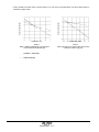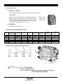
1
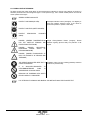
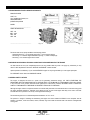
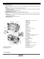
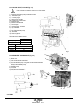
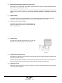
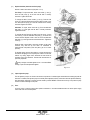
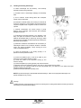
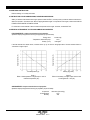
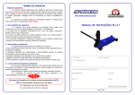
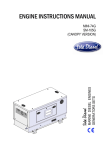
ENGINE INSTRUCTIONS MANUAL
MARINE DIESEL ENGINES
MARINE DIESEL GENSETS
SDZ-165 / SDZ-165G
SDZ-205
SDZ-280
This engine instructions manual is also available in
the following languages
ENG
This operator’s manual is available in English.
Part no. 03919402.ENG
Download from our web page www.solediesel.com
or order to [email protected]
SP
Este manual de instrucciones puede solicitarse en español.
Ref. 03919402.SP
Descargar desde nuestra web www.solediesel.com
o pedir a través mail [email protected]
“Solé S.A. seeks for the constant improvement of its final products, for that reason the design, description, dimension, configuration
and other technical specifications herein, appear just as an informative note that can not be understood as a binding offer referred to
the final product. The technical specifications and presentations are subject to variations and modifications without being obliged to
proceed with any previous notice”.
CONTENTS
0. INTRODUCTION
0.0 FOREWORD
0.1 USING THE INSTRUCTION MANUAL
0.1.1 IMPORTANCE OF THE MANUAL
0.1.2 CONSERVING THE MANUAL
0.1.3 CONSULTING THE MANUAL
0.1.4 SYMBOLS IN THE MANUAL
ENG-1
ENG-2
1. GENRAL INFORMATION
1.1 ENGINE MANUFACTURER’S INDENTIFICATION DATA
1.2 INFORMATION REGARDING TECHNICAL ASSISTANCE / MAINTENANCE OF THE ENGINE
1.3 GENRAL SAFETY NOTICIES
1.3.1 INFORMATION REGARDING RESIDUAL RISKS
1.3.2 SAFETY REGULATIONS
2. PRELIMINARY INFORMATION ON THE ENGINE
2.1 GENERAL DESCRIPTION
2.2 COOLING CIRCUIT
2.2.1 COOLING CIRCUIT, COOLANT
2.2.2 “SEAWATER” COOLING CIRCUIT
2.3 LUBRICATION CIRCUIT
2.3.1 ENGINE
2.3.2 GEARBOX
2.4 FUEL CIRCUIT
2.4.1 INJECTION PUMP
2.5 ELECTRICAL PLANT
2.5.1 ELECTRICAL PLANT AND INTRUMENT PANEL (PROPULSION ENGINE)
2.5.2 ELECTRICAL PLANT INSTRUMENT PANEL (GENSET VERSION)
2.6 TECHNICAL SPECIFICATIONS
2.6.1 ENGINE DIMENSIONS (PROPULSION VERSION)
2.6.2 ENGINE DIMENSIONS (GENSET VERSION)
2.7 GEARBOX, GENERAL INFORMATION
ENG-3
ENG-4
ENG-5
ENG-6
ENG-7
ENG-8
ENG-9
ENG-10
ENG-11
ENG-12
ENG-13
3. TRANSPORT, HANDLING AND STORAGE
3.0 GENERAL WARINGS
3.1 PACKING AND UNPAKING
3.1.1 PACKING AND UNPAKING WITH PALLET AND WOODEN CRATE
3.1.2 PACKING AND UNPAKING WITH PALLET AND SKELETON CRAT
3.1.3 PAKING AND UNPAKING WITH ENGINE MOUNTING FIXTURE AND PLASTIC PACKAGIN
3.2 RECEIPT
3.2.1 PACKING LIST
3.3 TRANSPORT AND HANLING THE PACKED ENGINE
3.4 TRANSPORT AND HANDLING OF THE UNPACHED ENGINE
3.5 STORAGE OF PACKED AND UNPACKED ENGINE
ENG-14
4. INSTALATION
4.0 GENERAL WARINGS
4.1 ASSEMBLY DATA
4.2 ENGINE SUPPLIES
4.2.1 CHANGING OIL
4.2.1.1 CHANGING ENGINE SUMP OIL
4.2.1.2 CHANGING GEARBOX OIL
4.2.2 FILLING THE COOLING CIRCUIT
4.2.3 REFUELING
4.3 INSTALLATION
4.4 INDICATIONS FOR REMOVAL / DISPOSAL OF WASTE MATERIAL
ENG-16
ENG
03919402.ENG rev. 0
ENG-15
ENG-17
ENG-18
ENG-19
CONTENTS
5. PREPARING THE ENGINE FOR USE
5.0 GENERAL WARINGS
5.1 INSTRUCTIONS FOR FIRST STARTING
5.1.1 BLEEDING AIR FROM THE FUEL SUPPLY SYSTEM
5.2 PRELIMINARY RUNNING TEST
5.2.1 NO-LOAD RUNNING TEST
5.2.2 RUNNING – IN
6. USING THE ENGINE
6.0 GENERAL WARINGS
6.1.STARTING AND STOP THE ENGINE (PROPULSION VERSION)
6.2. STARTING AND STOP THE ENGINE (GENSET VERSION)
6.3 USING THE ENGINE INFREQUENTLY
6.4 OPERATING THE ENGINE AT LOW TEMPERATURES
6.5 CONSERVATION
6.6 LONG INACTIVITY INSTRUCTIONS
6.7 RESTORATION OF THE RUNNING CONDITIONS
7. REPAIR AND MAINTENANCE
7.0 GENERAL WARNINGS
7.1 TYPE AND FREQUENCY OF INSPECTIONS AND MAINTENANCE INTERVENTIONS
7.2 OPERATION DESCRIPTION
7.3 TROUBLE SHOOTINGS
ENG-20
ENG-21
ENG-22
ENG-23
ENG-24
ENG-25
ENG-26
ENG-28
ENG-35
8. ADDITIONAL INSTRUCTIONS
8.0 ADDITIONAL INSTRUCTIONS
8.1 ISNTRUCTIONS FOR DECOMMISSIONING, SCRAPPING AND DISPOSAL
8.2 DERATING OF ENGINE DUE TO FUEL AND COMBUSTIO PROPERTIES
ENG-36
9. TECHNICAL ANNEXES
9.0 OIL SPECIFICATIONS
9.0.1 ENGINE OIL TO BE USED
9.0.2 GEARBOX OIL
9.1 ESPECIFICATIONS FOR ENGINE INSTALLATION
9.2 POWER TAKE-OFF ESPECIFICATIONS (OPTIONALS)
ENG-38
ENG
03919402.ENG rev. 0
0. INTRODUCTION
0.0 FOREWORD
Dear client:
The SOLÉ S.A. engine you have purchased is a product of the highest technological quality Our Service SOLÉ DIESEL
department has recently been strengthened to ensure even better service for all our clients. Reliable duty and long life of the
engine you have purchased can only be guaranteed if you use exclusively original spare parts and ensure that the unit is
serviced by our specialized personnel.
We therefore recommend that you insist on having your SOLE S.A. engine serviced EXCLUSIVELY by our Service SOLÉ
DIESEL Department. If engines manufactured by SOLÉ S.A. are serviced by unauthorized technicians, or non-original spare
parts are utilized, ALL WARRANTY SPECIFICS OF SOLÉ S.A. ARE INVALIDATED.
We are confident that you will understand the importance of these recommendations, which are made for purely technical
reasons and serve to defend our clients and ensure their full satisfaction with our products.
Please get in contact with our nearest official service for any requirements you may have.
0.1 USING THE INSTRUCTION MANUAL
0.1.1 IMPORTANCE OF THE MANUAL
This INSTRUCTION MANUAL is your guide to the USE and MAINTENANCE of the engine you have just purchased. We strongly
recommend that you follow all the advice in the manual meticulously, because the correct operation and lasting reliability of the
engine depend on its correct use and the methodical application of the programmed maintenance operations illustrated in these
pages.
If you run into difficulties or setbacks, Service SOLÉDIESEL department will be happy to provide you with the necessary advice
and assistance.
This INSTRUCTION MANUAL is an integral part of the product you have acquired. Please conserve it in a safe place for the full
working life of the engine.
SOLÉ S.A. reserves the right to make changes aimed at improving its products without any form of prior notification.
Please ensure that you enclose with the original publication of the present manual any amendments or updates that you
may receive.
Deliver this manual to all users of the engine or future owners.
0.1.2 CONSERVING THE MANUAL
When using the manual make sure that it is not damaged or defaced. Do not remove or rewrite any parts of the manual for any
reason. Conserve the manual in a dry and heat protected place.
0.1.3 CONSULTING THE MANUAL
This instruction manual comprises:
· COVER PAGE WITH INDICATION OF THE FAMILY TO WHICH YOUR ENGINE BELONGS. The cover page shows the model
of the engine described in the manual.
· TABLE OF CONTENTS. Use the contents page to find the page containing information relative to a given argument.
· INSTRUCTIONS AND/OR NOTES ABOUT THEPRODUCT. All the INSTRUCTIONS AND/OR NOTES ON THE PRODUCT are
designed to define safety practices, proper procedures and the skills required for correct operation of the engine.
The annexes at the end of this manual are an integral part of the same. Please note that the illustrations in the manual, which
have been included to help you identify the parts described in the text, show standard or prototype engines and may therefore
differ, in some respects, from the engine in your possession.
ENG - 1
03919402.ENG rev. 0
0.1.4 SYMBOLS USED IN THE MANUAL
The Safety symbols and notices shown below are used throughout this publication to draw the user’s attention to situations or
hazardous procedures that could damage the engine or cause personal injury, and to indicate suitable practices to assure the
correct operation of the engine.
GENERAL OPERATIONAL NOTE
PROTECT YOUR HANDS(GLOVES)
Prescription-Indication notices (rectangular); it is obligatory to
adopt the protective measures shown in the notices to
perform the operation in question in total safety:
PROTECT YOUR EYES (SAFETYGLASSES)
PROTECT
(MASK)
RESPIRATORY
PASSAGES
DANGER!, (GENERAL DANGERSITUATION
FOR THE SAFETYOF PERSONS AND
PROTECTIONOF THE ENGINE)
DANGER!,
(DANGER
DISCHARGES FORTHE
PERSONS ANDENGINE)
Danger Warning-Attention Notices (triangular); General
Attention regarding personal safety and protection of the
engine:.
OFELECTRICAL
SAFETY
OF
DANGER!, (DANGER FROMSOURCES OF
HEAT FOR THESAFETY OF PERSONS AND
THEENGINE)
THE OPERATION INDICATED INTHE TEXT IS
STRICTLYPROHIBITED
IT
IS
ABSOLUTELYPROHIBITED
PERFORMMAINTENANCE
WORK
THEPRESENCE OF MOVING PARTS
Prohibition notices (circular) indicating potentially hazardous
situations for personal safety:
TO
IN
REMOVING OR TAMPERING WITH SAFETY
DEVICES ISSTRICTLY PROHIBITED
PAY ATTENTION TO SYMBOLS AND OBSERVE THE INSTRUCTIONS IN THE ADJACENT TEXT
0. INTRODUCCIÓN
ENG - 2
03919402.ENG rev. 0
1. GENERAL INFORMACION
1.1 ENGINE MANUFACTURER’S IDENTIFICATION DATA
MANUFACTURER:
SOLÉ, S.A.
Ctra. de Martorell a Gelida, km 2
08760 MARTORELL
(BARCELONA) SPAIN
MODEL:
_____________________________
TRADE DESIGNATION:
Fig. 1.1a
Fig. 1.1b
SDZ - 165
SDZ - 165G
SDZ - 205
SDZ - 280
______________________________
Fig. 1.2
Fig. 1.3.
The above data can be quickly identified in the following position:
- Check the plaque Fig. 1.1a for genset and the Fig. 1.1b for propulsion engine.
- See the Fig. 1.2 to read the engine identification (see fig. 1.1, detail of the plaque).
- See the fig. 1.3 to read the engine serial number.
1.2 INFORMATION REGARDING TECHNICAL ASSISTANCE AND MAINTENANCE OF THE ENGINE.
Our after sale service is at your complete disposal to solve any problems that may arise or to supply any information you may
need. For ANY explanations refer to the “SERVICE SOLÉDIESEL” address booklet.
Optimal operation and efficiency of your new SOLÉDIESEL engine can only be guaranteed if you use original spare parts.
For WARRANTY terms refer to the WARRANTY MAUAL.
1.3 GENERAL SAFETY NOTICES
The engine is designed and built as a power unit for generating mechanical energy: ALL USES OTHERTHAN THE
PRESCRIBED APPLICATIONAUTOMATICALLY RELEASE SOLÉ S.A. FROMLIABILITY FOR DAMAGES THAT MAY ENSUE,
in any event, the use of products other than those agreed upon at the time of purchase, RELEASES SOLÉ S.A.FROM ALL
LIABILITY FOR DAMAGE TO THEENGINE OR PROPERTY OR INJURY TO PERSONS.
Although the engine is built in compliance with the most recent safety standards it is advisable to bear in mind that moving parts
are always potentially dangerous. Therefore, never attempt to work on parts of the engine while they are in motion and make
sure that there are no persons in the vicinity of the engine before starting it.
The standard engine can run at ambient temperatures between -18 ºC a +45 ºC.
The operator in charge of installing and maintaining the engine must wear suitable CLOTHING for the workplace and the
situation; in particular, avoid loose clothes, chains, bracelets, rings and all other accessories that could become entangled with
moving parts..
ENG - 3
03919402.ENG rev. 0
The area in which the operator is working must be kept tidy and free of oil and other liquid spillages and solid waste (metal chips,
etc.).
Before starting work the operator must be aware of the position and operation of all commands and the characteristics of the
engine; make a daily check of the safety devices on the engine. Disabling or tampering with the safety devices on the engine is
strictly prohibited. Do not attempt to perform maintenance work adjustments or reset tings on moving parts on the engine; before
performing any of the above operations disconnect the electrical supply to ensure that no other persons can start the engine up
in the meantime.
Do not alter any parts of the engine (for example connections, holes, finishes, etc.) to adapt it to the installation of extra
equipment or for any other reason; THE RESPONSIBILITY FOR ANY TYPE OFINTERVENTION NOT EXPRESSLY
AUTHORISEDIN WRITING BY SOLÉ S.A. IS BORNEEXCLUSIVELY BY THE PERSON OR PERSONSWHO CARRY OUT
SUCH WORK.
SOLÉ S.A. DECLARES THAT THE ENGINECHARACTERISTICS ARE COMMENSURATEWITH THE PARAMETERS
PERMITED BYESTABLISHED LAW REGULATIONS REGARDINGTHE EMISSION OF:
-AIRBONE NOISE
-POLLUTING EXHAUST GAS
WHEN USING THE MOTOR IN A CLOSEDENVIRONMENT THE EXHAUST FUMES MUST BECONVEYED OUTSIDE..
1.3.1 INFORMATION REGARDING RESIDUAL RISKS
The engine must be used in compliance with the manufacturer’s prescriptions (technical specifications, safety regulations, etc.).
Any modifications you make be previously authorized by the Manufacturer. If you use the engine beyond its application limits and
alter in any way the characteristics that are the responsibility of SOLÉ S.A., such use shall be considered improper and SOLÉ
S.A. declines all liability for the consequences (see notes regarding intended use in General Safety Notices 1.3).
DO NOT TAMPER WITH ORMODIFY ANY MECHANICAL OR ELECTRICAL COMPONENTS OF THE ENGINE
WITHOUT PIOR WRITTEN AUTHOR ISATION FROM THE MANUFACTURER
1.3.2 SAFETTY REGULATIONS
IT’S STRICTLY PROHIBITED TO PERFORM MAINTENANCEWORK WHILE THERE AREENGINE PARTS
MOVING.
IT’S STRICTLY PROHIBITED TO REMOVE OR TAMPERWITH THE SAFETY DEVICES
WHEN THE ENGINE ISRUNNING IT IS STRICTLYPROHIBITED TO TOUCHANY PARTS OF IT
ALWAYS PROTECT THEHANDS WITH SAFETY GLOVES AND HEAT RESISTANT CLOTHING WHEN
WORKING ON A HOT ENGINE
PROTECT THE RESPIRATORY PASSAGES WHEN WORKING IN THE VICINITY OF ENGINE EXHAUST GAS
ENG - 4
03919402.ENG rev. 0
2. PRELIMINARY INFORMATION ON THE ENGINE
2.1 GENERAL DESCRIPTION
(1) Direction of Rotation: clockwise observing engine from side opposite flywheel. Counter-Clockwise observing engine from
flywheel.
(2) Timing: pushrod and rocker arm with gear driven camshaft in crankcase.
(3) Air Supply: air clearing by jeans of a dry-type air filter. Turbocharger used in all models. SDZ-165, SDZ-165G and SDZ-280
equipped with an intercooler.
(4) Fuel System: equipped with mechanical priming pump.
(5) Combustion System: Direct Injection.
(6) Injection Pumps: Single injection pump for each cylinder integrated in crankcase.
(7) Cycle: diesel 4 stroke. 4 cylinders in-line for SDZ-165 and SDZ-165G and 6 cylinders in-line for model SDZ-205 and SDZ280.
(8) Cooling System: liquid cooled circulation controlled by centrifugal puma with thermostatic control and heat exchanger. Also,
the exhaust manifold is cooled.
(9) Lubrication: forced-feed lubrication by gear-pump.
(10) Electrical System: 24V.
1. Filler cap for the coolant on the expansion tank
2. Expansion tank
3. Heat exchanger
4. Freshwater pump
5. Vibration damper
6. Fuel feed pump
7. Fuel inlet
8. Fuel filter
9. Lubrication oil filter
10. Oil dipstick
11. Connection power take-off (optional)
12. Seawater pump
13. Plug
14. Inlet seawater pump
15. Fuel overflow valve
16. Governor
17. Stop solenoid
18. Fuel injection line
19. Ventilation line from turbocharger to expansion tank
20. Seawater line to air heat exchanger
21. Oil filler cap
22. Oil cooler, engine
23. Fuel injection pumps
24. Starter motor (4 kW, 28V)
25. Oil sump
26. Oil drain pump
27. Alternator ( 55 A, 28V)
28. Exhaust manifold
29. Coolant line from charge air cooler to heat
exchanger
30. Seawater outlet
31. Charge Air cooler (only model SDZ-165)
32. Turbocharger
34. Lubricating line to turbocharger
36.Flywheel (size SAE 11 ½”)
33. Coolant line to turbocharger
35. Flywheel housing (size SAE 3”)
37. Elbow, wet exhaust
2.2 COOLING CIRCUIT
ENG - 5
03919402.ENG rev. 0
2.2.1 COOLING CIRCUIT, COOLANT (Fig. 2.1)
Use anti-freeze as indicated in section 4.2.2 of this manual.
1) Expansion tank/coolant pump compensation hose
2) “Freshwater” pump.
3) Oil cooler (engine)
4) Cooling circuit, cylinders
4A) Cooling circuit, cylinder head
5) Expansion tank
6) Exhaust manifold cooled
7) Turbo charger
8) Heat exchange, anti-freeze
9) Pipe, seawater
10) Elbow, wet exhaust
11) Pipe, inlet freshwater pump
12) Thermostat
13) Boiler kit (optional)
Thermostat valve operating values:
Start opening at …
Fully opened at …
SDZ – 165
SDZ– 205
SDZ-280
All Engines
87 ºC
102 ºC
CIRCUIT CAPACITY (LIT.)
17.5
20
24
Fig. 2.1
2.2.2 “SEAWATER” COOLINGCIRCUIT (Fig. 2.2)
1)
2)
3)
4)
Bottom cock
Intake connection with water filter
Oil cooler gearbox
Pipe, inlet seawater pump. For genset connect the inlet seawater
Directly to the sea water pump
5) Seawater pump
6) Intercooler
7) Heat Exchange (“freshwater”)
8) Elbow, wet exhaust
6
8
7
3
2.3 LUBRICATION CIRCUIT
ENG - 6
03919402.ENG rev. 0
4
Fig. 2.2
2.3.1 ENGINE (Fig 2.3.1)
Lubrication is forced with a lobe pump and total filtration of the oil pumped to the various lube points on the engine.The oil is
forced by the pump through a control valve to the filter, the engine main bearings and, by way of external pipelines, to the rocker
arms.
Fig. 2.3.1
1) Oil pan
2) Scoop
3) Oil pump
3a) Valve, flow control
3b) Valve, maximum pressure
4) Oil cooler (engine)
5) Oil filter, element
6) Oil pipe
7) Bearing, crankshaft
8) Bearing, connecting rod
9) Bearing, camshaft
10) Pipe, cooling cylinder
11) Pipe, cooling cylinder
12) Tappet
13) Rod, cooling rocker
14) Rocker
15) Pipe, to oil pan
16) Oil pressure sender
17) Pipe, to turbo charger.
19) Pipe, to compressor or hydraulic pump (optional)
24) Pipe, from turbocharger to oil pan
18) Turbo charger
23) Pipe, to oil pan
25) Pump, oil suction
Oil circuit pressure (with hot engine):
(1) Oil pressure at idling speed = 0.8 kg/cm2
(2) Oil Pressure at operating speed (1100 rpm or higher) = 4.5 kg/cm2
ENGINE
OIL CAPACITY
(LITERS)
SDZ – 165
10
SDZ – 165G
10
SDZ – 205
21
SDZ-280
21
Engine equipped with Standard oil pan, no engine inclination
and with oil filter
2.3.2 GEARBOX
Gearbox has its own lubrication,independent from the engine.See fig. 2.2
Only for propulsion engine
ENG - 7
03919402.ENG rev. 0
2.4 FUEL CIRCUIT
Fig. 2.4
1) Fuel tank
2) Marine hose fuel (certificated)
3) Fuel pump
4) Fuel pipe, to fuel filter
5) Fuel filter
6) Fuel pipe, to the singles injections pumps
7) Injections pumps
8) Pipe to injectors
9) Injectors
10) Fuel pipe, return
11) Valve
12) Marine fuel hose (to the tank)
13) Distance between inlet and outlet. It must be bigger
14) Fuel filter (water separator).
ENGINE
SDZ – 165
SDZ – 165G
SDZ – 205
SDZ-280
INJECTORS
4
4
6
6
Fig. 2.4
1) Fuel pump
2) Fuel filter (engine)
3) Marine fuel hose. Read the next comment at the bottom of the page.
4) Fuel filter (water separator)
5) Valve
6) Fuel pump, manual. Not supplied (optional, order kit 19424075)
7) Fuel tank
8) Breather tank
9) Fuel cooler** (optional)
10) Marine fuel hose, to the tank. Read the next comment at the bottom
of the page.
11) No-return valve (not supplied)
12) Injector
13) Fuel pump
Not surpass the 2 m of height between the tank and fuel pump.
The distance L will be the maximum.
For the aspirations and return fuel hose interior diameters (Ø) and lengths (L) follow these specifications:
-
Ø 12 mm when L < 6 m
Ø 14 mm when L < 15 m
Ø 16 mm when L < 25 m
**High pressure injection pumps increase the temperature of fuel. An increase of temperature of 30°C measured
between the injection pump inlet and fuel return line may result in a loss of 1.5% of power for each 10°C. Install a
fuel cooler of 2-4 kW to reduce this fact. Maximum permissible fuel temperature is 75°C.
2.4.1 INJECTORS
Opening Pressure = 275 bar
ENG - 8
03919402.ENG rev. 0
2.5 ELECTRICAL PLANT
2.5.1 ELECTRICAL PLANT INSTRUMENT PANEL (SDZ-165, SDZ-205, SDZ-280)
A
B
C
D
E
F
G
H
I
J
K
L
M
N
O
DESCRIPTION
GLOW PLUG OPERATION LAMP (not active)
BATTERY CHARGE LAMP
WATER TEMP. ALARM LAMP
OIL PRESSURE ALARM
KEY STARTER
TACHOMETER
VOLTIMETER GAUGE
HOUR COUNTER
FUSE
ALARME
FUSE
OIL PRESSURE GAUGE
COOLANT TEMP. GAUGE
RESISTENCE 200 Ω
RESISTENCE 100 Ω
Standard Panel (24V)
Part no. 609.94.125
ENG - 9
03919402.ENG rev. 0
2.5.2 ELECTRICAL PLANT INSTRUMENT PANEL (SDZ-165G)
Check the panel service manual and the electrical wiring attached with the genset.
ENG - 10
03919402.ENG rev. 0
2.6 TECHNICAL SPECIFICATIONS
Cylinders Number
Diameter
Bore
Total Displacement
Compression Ratio
r.p.m. (idling speed)
Max. Engine Speed
Type y Ratio
Gear box
UNITS
SDZ – 165
SDZ – 205
SDZ – 280
SDZ – 165
SDZ – 165
SDZ – 165
mm
mm
c.c.
4
108
130
4764
17.6 : 1
6
108
130
7146
17.6 : 1
6
108
130
7146
17.6 : 1
750 ± 5
750 ± 050
750 ± 50
4
108
130
4764
17.6 : 1
----
4
108
130
4764
17.6 : 1
----
4
108
130
4764
17.6 : 1
----
1500 ± 25
1500 ± 25
1500 ± 25
TM-265A
---
2300
2.04 : 1
2.5 : 1
2.94 : 1
2.08 : 1
2.6 : 1
2.09 : 1
2.82 : 1
2.09 : 1
2.3 : 1
2300
---
TM-265
2300
2.04 : 1
2.5 : 1
2.94 : 1
2.08 : 1
2.6 : 1
---
MeccAlte
ECP34-1S
---
MeccAlte
ECP34-2S
---
r.p.m.
r.p.m.
TM-170
TM-170A
(G-71T-15)
(G-85T-15)
(G-104T-15)
--2.09 : 1
2.82 : 1
2.09 : 1
2.3 : 1
Generator
º
10
10
10
MeccAlte
EC032-3L/4
---
kW / CV
kW / CV
118 / 160
105 / 144
145 / 197
132 / 180
200 / 272
180 / 245
87 / 118
---
87 / 118
---
87 / 118
---
Oil Capacity (with filter)
Oil Capacity (without filter)
Gearbox oil Capacity
( liters )
Liters
Liters
TM-170
TM-170A
TM-265
TM-265A
14
13
2.5
2.5
-------
21
20
2.5
2.5
5.5
5.5
21
20
------5.5
5.5
14
13
14
13
14
13
Min. Oil Pressure
(hot engine)
Cooling Water Capacity
Injection Pump
Injection Pressure
Ignition Sequence
Valve Timing (intake open)
Valve Clearance - Inlet
(cold engine)
Valve Clearance - Outlet
(cold engine)
Weight Dry with Gearbox
(kg)
kg/cm2
0.8
0.8
0.8
0.8
0.8
0.8
liters
17.5
BOSCH
250 / 275
1-3-4-2
20
BOSCH
250 / 275
1-5-3-6-2-4
BOSCH
250 / 275
1-5-3-6-2-4
17.5
BOSCH
250 / 275
1-3-4-2
17.5
BOSCH
250 / 275
1-3-4-2
17.5
BOSCH
250 / 275
1-3-4-2
mm
0.3
0.3
0.3
0.3
0.3
0.3
mm
0.5
0.5
0.5
0.5
0.5
0.5
TM-170
TM-170A
TM-265
TM-265A
G71T15
G84T15
G104T15
(kg)
698
698
808
808
818
818
928
928
Max. continuous working
angle
Crankshaft Power (1)
Propeller Shaft Power (1)
(1) ISO 8665
Weight Dry, bobtail version
bar
978
1015
617
737
ENG - 11
03919402.ENG rev. 0
617
617
1125
617
2.6.1 ENGINE DIMENSIONS
SDZ165 + TM170
SDZ205 + TM170
(1) Hose, Inlet seawater pump (ØInt 42mm).
(2) Hose, Inlet fuel pump (ØInt 12mm).
(3) Hose, return fuel pump (ØInt 12mm).
ENG - 12
03919402.ENG rev. 0
SDZ280 + TM265
2.6.2 GENSET DIMENSIONS.
2.7 GEARBOX (PROPULSION ENGINE) AND GENERATOR (GENSET VERSION)
Check specific manuals for these parts.
ENG - 13
03919402.ENG rev. 0
3. TRANSPORT, HANDLING, STORAGE
3.0 GENERAL WARNINGS
Refer to heading 1.3 for safety information.
3.1 PACKING AND UNPACKING
The engine is shipped in various types of packing systems:
Pallet with wooden crate (See heading
3.1.1)
-Pallet with skeleton crate (See heading
3.1.2)
-Engine mounting base + plastic
packaging(See heading 3.1.3)
STORAGE
Covered area only.
STACKING OF PACKS:
Max. 1+1
Covered area only.
NO
Covered area only.
NO
3.1.1 PACKING AND UNPACKING WITH PALLET AND WOODEN CRATE
Remove the lower nails. Lift the engine using chains with safety hooks and of suitable load capacity. Attach the chain hooks
to the engine eyebolts and lift using a forklift or other suitable lifting equipment as described in heading 3.3.
Transfer the engine to the intended position of installation and remove the plastic wrap film. Unscrew screws that secure the
engine to the wooden base withdraw and proceed with installation operations.
3.1.2 PACKING AND UNPACKING WITH PALLET AND SKELETON CRAT
Remove the lower nails. Lift the engine using chains with safety hooks and of suitable load capacity. Attach the chain hooks
to the engine eyebolts and lift using a forklift or other suitable lifting equipment as described in heading 3.3.
Transfer the engine to the intended position of installation and remove the plastic wrap film. Unscrew screws that secure the
engine to the wooden base with draw the base and proceed with installation operations.
3.1.3 PACKING AND UNPACKING WITH ENGINE MOUNTING FIXTURE AND PLASTIC PACKAGIN
Lift the engine using chains with safety hooks and of suitable load capacity. Attach the chain hooks to the engine eyebolts
and lift using a fork lift or other suitable lifting equipment as described in heading 3.3.
Transfer the engine to the intended position of installation and remove the plastic wrap film. Unscrew screws that secure the
engine to the wooden base with draw the base and proceed with installation operations.
3.2 RECEIPT
When the engine is delivered make sure that the packing has not been damaged during transport and that it has not been
tampered with or that components inside the packing have been removed (see information marked on covers, bases and
cartons).
Place the packed engine as close as possible to the place of installation and remove the packing material, checking that the
goods supplied correspond to the order specifications.
if you notice damage or missing parts, inform Solé diesel assistance departments and the carrier immediately and
forward photographic evidence of the damage
important:
After inspecting the goods if you notice damage duo to transport. Have the transport company delivery note and
inform SOLE S.A.,
ENG - 14
03919402.ENG rev. 0
3.2.1 PACKING LIST
(1) ASSEMBLED ENGINE
(2) TECHNICAL DOCUMENTATION
The technical documentation contains: instruction and user manual.
Packing material must be disposed of in compliance with established law in the user’s country. Packing materials:
Wood Steel nails Steel screws Plastic film Cardboard Metal or plastic straps
3.3 TRANSPORT AND HANDLING THE PACKED ENGINE
When lifting and transporting the engine use EXCLUSIVELLY a fork lift or bridge crane of appropriate load capacity, with
chains equipped with safety hooks suitable for lifting the load in question.
The use of any other system automatically invalidates the insurance guarantee against possible damage to the engine.
3.4 TRANSPORT AND HANDLING OF THE UNPACKED ENGINE
When the engine is unpacked ready for transport, use EXCLUSIVELLY the appropriate lifting eyebolts (A), see the picture 3.4.
Choose the lifting equipment with reference to heading 3.3.
Fig. 3.4
3.5 STORAGE OF PACKED AND UNPACKED ENGINE
If the engine is left idle for prolonged periods, the client must check the possible conditions of conservation in relation to the
place of storage and the type of packing system (base, pallet, etc.).
If the engine is unused for prolonged periods and stored, observe all the relative technical specifications.
The treatment of the engine for storage is guaranteed for 6 months after the time of delivery..
if the user decides to start the engine after a longer time period, this must bed one in the presence of an
authorized technician
ENG - 15
03919402.ENG rev. 0
4. INSTALLATION
4.0 GENERAL WARNINGS
Refer to heading 1.3 for safety information
4.1. ASSEMBLY DATA
(kgf · m)
PARES DE APRIETE
Bolt, cylinder head
Bolt, crankshaft pulley
Bolt, metal cap
Bolt, connecting rod
Bolts, Flywheel (length 30-45 mm)
Bolts, Flywheel (length 50-85 mm)
Plug, oil pan
Oil filter
Pressure relief valve
Bolts to fix the Flange injections pumps
Glow Plugs
Bolt, Stop solenoid
Nut for B terminal of starter
Bolts, reversing gear flange set
Water cooler element locknut
Reversing gear body set screw
Oil gearbox drain plug
General tightening torque
SDZ-165
SDZ-165G
13
4–5
5
3
2–3
3-4
5
1.5
4–5
5
2
2.1
1.1
12.0
2.3
5
3.5
M6 …. 1.0
M8 …. 2.5
M10 … 6.0
M12 … 10.0
SDZ-205
SDZ-280
13
4-5
5
3
2-3
3-4
5
1.5
4-5
5
2
2.1
1.1
12.0
2.3
5
3.5
M6 …. 1.0
M8 …. 2.5
M10 … 6.0
M12 … 10.0
1st retightening angle 60°, 2nd angle 30° (60
mm long bolts) 60° (80 mm long bolts)
For the Connecting Rod Bolts, please read
the comment (1) and for the Flywheel bolts,
please read the comment (2).
Comments:
(1) 1st tightening angle = 60º /////
2nd tightening angle bolts = 60º
(2) 1st tightening angle bolts 30-85 mm length = 60º
2nd tightening angle bolts 30mm length = 30º ///// 2nd tightening angle bolts 35-85mm length = 60º
Bolts may be used 5x if evidence can be furnished concerning their use
CYLINDER HEAD BOLTS TIGHTENING SEQUENCE:
When bolting the cylinder head, clean thoroughly the contact faces and fit the head gasket. Retighten one screw at a time when engine
is cold as indicated in the suitable drawing. Loosen must be done using the reverse sequence.
A = Manifold side
SDZ-165
Tightening torque, 1st stage = 50 Nm
Tightening torque, 2nd stage = 130 Nm
Tightening angle = 90º
SDZ - 205 / SDZ-280
Cylinder head bolts may be used max. 5 times. If evidence can be
furnished concerning their use.
Tighten M8 bolt with a torque of 21 Nm.
ENG - 16
03919402.ENG rev. 0
4.2 ENGINE SUPPLIES
The engine does not come with its circuits filled with the applicable fluids.
4.2.1 CHANGING OIL
4.2.1.1 CHANGING ENGINE SUMP OIL
Use oil that corresponds to the technical specifications in
chapter 9.
The oil must be changed with warmed engine, in order to
ensure that is emptied. The temperature of the oil will be
approximately 80 ºC. Stop the engine before doing the oil
change.
This operation is done by oil drain pump (see Fig 4.1).
Dismount the plug (A) and fit the hand oil pump. Connect a
hose from the oil drain pump to a container. Process the old oil
in accordance with the local regulations.
(A)
Fig. 4.1
When drained, fill with new oil through the filling hole. (Fig. 4.2).
Oil capacity: see heading 2.6 (technical specifications).
Immediately operate engine at idling for some minutes until the
dashboard control light is switched off.
Stop engine. Check filter and engine sealing. Check then oil
level, by removing the oil dipstick (Fig. 4.3), cleaning it with a
rag and repositioning it by retightening.
Fig. 4.2
Remove it again immediately to check oil level and if it does not
reach the top sign add carefully more oil through the filler hole
(Fig. 4.2) up to the top dipstick mark.
The oil level must be between the mark MIN and MAX.
Fig. 4.3
WARNING
The level of oil never to being below the mark MIN of the oil dipstick.
Fig. 4.4
Note that dipstick marks refer to the engine at a horizontal position. Therefore, check the engine inclination
when the level is verified.
If the engine is fitted inclined, the marks must be modified. Read the technical annexes to modify the marks.
Read the technical specifications to the MAX inclination (page 10).
ENG - 17
03919402.ENG rev. 0
4.2.1.2 CHANGING GEARBOX OIL
Gearbox has its own lubrication, independent from the engine.
warning:
the use of oil that does not conform to the technical specifications on chapter 9 will cause serious damage to
the engine and invalidate the guarantee
When supplying the engine never ingest oil, fuel, coolant liquid, etc.. these substances are harmful to the
personal health of the user if ingested
4.2.2 FILLING THE COOLING CIRCUIT.
As a refrigerating liquid, an anti-freeze of the brand KRAFFT ACU
2300 CC 50% Ref. 1325 or another one with similar specifications
must be used.
The incorrect use of water in the refrigeration circuit is extremely
harmful, causing corrosion and scaling, while the use of anti-freeze
protects the circuit from corrosion, scaling and from freezing in
conditions of very low temperature, thus optimizing engine
maintenance and reliability.
Warning!
do not allow AC88 liquid to come into contact with the eyes or the skin
Warning!
do not ingest any of the liquids utilized to fill the various circuits on the engine
Fig. 4.2.2
Open de valve (plug) to clean the air (possible air bubbles) during this
process.
When distilled water is used in the refrigeration circuit, an anti-freeze product must be added, otherwise the expansion of
water when it freezes may produce cracks and damage to the refrigerator unit and to the block, and in proportion to the
temperatures expected.
The anti-freezing agent manufacturer, in the package labels is giving the instructions to be followed at each case.
However, in the following box, suitable rates a reset out in accordance with temperatures:
Ant freezing liquid concentration (%)
Freezing temperature (ºC)
30
-10
40
-20
50
-30
60
-45
It is advisable the anti-freezing agent strength is selected based on a temperature which is approx. 5 ºC under the actual
atmospheric temperature.
The anti-freeze solution recommended can be used for normal operation for 2 years. At the end of this period of time the
refrigeration circuit must be emptied and cleaned, then refilled with the predetermined anti-freeze (see 4.2.2). Read the
chapter 7.2 for draining circuit instructions.
ENG - 18
03919402.ENG rev. 0
Run the engine for a few minutes until the cooling circuit is properly filled and free of air bubbles. Check the coolant level
and refill if necessary.
Warning!
Never open the oil plug (1) when the engine is hot as it can release steam or splashes of hot coolant. Stop the
engine and wait until it gets cold to do the coolant change. See fig 4.2.2.
Warning!
After the first 50 hours of engine duty and thereafter at six months or 1000 hours intervals, add rust inhibiting
agent AC88 to the coolant in the same proportions as indicated in the table from section 4.2.2. The cooling
liquid mixture must be totally drained and replaced every 2 years
Warning!
To use refrigeration liquid that does not match the technical specifications causes damage to the components
of the engine, determining the cancellation of the warranty.
4.2.3 REFUELING
Use clean, filtered gas oil of ASTM D 975-88 quality. Never use either kerosene or heavy oils. On topping up with fuel,
use a funnel with a metallic mesh filter, to keep out impurities or foreign bodies which may cause problems in the fuel
injection circuit.
Whenever possible, keep the fuel tank full, as temperature changes may cause condensation of the damp air present in
the tank so that water accumulates at the bottom, giving rise to corrosion or making it impossible to start the engine if this
is aspirated by the fuel pump.
Check all tank filling plugs located at the boat deck are sealed.
Warning!
Do not use diesel fuel mixed with water or any other foreign substances
Warning!
Always use top quality fuel of certified origin. the use of diesel fuel that does not comply with the technical
specifications indicated above will cause serious damage to the injection system and hence to the engine and
also invalidate the terms of the guarantee
4.3 INSTALLATION
Warning!
When water-cooled engines must be located in an enclosed place or protected by guards or a cabinet, it is
important to ensure that combustion air is freely supplied and freely expelled from the area
The above recommendation is of primary importance in relation to the perfect operation of the engine because the hot air that
it generates must never be routed to the area of the combustion air intake cleaner.
If the user fails to take these precautions, a hot air recirculation system will be formed thus reducing engine power output and
obstructing proper cooling.
In these cases it is advised to take steps to avoid taking in engine combustion air from the place in which the engine is
installed. This is achieved by placing the suction filter, or a suction prefilter, outside the place in which the engine is installed.
4.4 INDICATIONS FOR REMOVAL / DISPOSAL OF WASTE MATERIAL
Warning!
Disposal of waste material must be carried out in conformity with established legislation in the country of
installation.
ENG - 19
03919402.ENG rev. 0
5. PREPARING THE ENGINE FOR USE
5.0 GENERAL WARNINGS
Refer to heading 1.3 for safety information.
5.1 INSTRUCTIONS FOR FIRST STARTING
Do not alter the functioning conditions of the engine by changing the settings of factory sealed parts. Tampering with such parts
automatically invalidates the guarantee. Proceed as follows when starting the engine for the first time:
(a) FILLING WITH OIL. Read the page nº8 to the oil capacity
(b) FILLING WITH COOLANT. Read the page nº 7 to the coolant capacity.
(c) REFUELING. Read the page nº 17. (heading 4.2.3). Check fuel delivery cock is fully opened.
(d) OPEN SEAWATER ENTRY COCK.
(e) CONNECT THE BATTERY CONNECTOR
(f) REMOTE CONTROL CONNECTION (only for propulsion engine)
(f.a) Engine control remote connection
Connect control cable to the ball-joint fitted to the lever (A)
and position the cable with the clamp (B).
Adjust in a way that gas is not delivered until the inverter
gear is engaged (Fig. 5.1)
Fig. 5.1
(f.b) Gearbox control remote connection.
Connect control cable to the lever by means of the balljoint provided for this purpose and position cable with the
clamp. When fitted, adjust control in a way that it has the
same forward running that rearward and gas is not
delivered until the gear is perfectly engaged (Fig.5.2).
To check fitting is correct, proceed as follows: Place the
gearbox lever and remote control lever in the position of
forward running. Adjustment is made by way of the
elongated holes of the control and the elongated holes of
the cable attachment support.
Fig. 5.2
(g) OTHER CHECKINGS
(g.a) Carefully check the engine positioning points.
(g.b) Check all screws are correctly tightened.
(g.c) Check all water, oil and gas-oil pipe nipples, verifying if all them are well connected and correctly tightened.
(g.d) Check exhaust and transmission systems.
ENG - 20
03919402.ENG rev. 0
5.1.1 BLEEDING AIR FROM THE FUEL SUPPLY SYSTEM
On the first start-up of the engine, and if this
has operated with the fuel tank empty, air
may enter the feed system, and it is
necessary to purge this. To carry out the
priming/purge of the fuel system, proceed as
follows:
(1) Check that fuel intake valve located at the
tank is open.
(2) Place a recipient under the fuel return
valve (B), remove the plastic cap from the
pipe.
(3) Press, several times, the manual fuel feed
pump (A), until the fuel bleeds without air
bubbles from fuel return valve (B).
(4) Connect the fuel return line to the fuel
tank
(5) Start the engine and make sure there are
no leaks.
Fig. 5.3
Warning!!
Protect hands. The fuel can harm the skin.
5.2 PRELIMINARY RUNNING TESTS
5.2.1 NO-LOAD RUNNING TEST
Run the engine at low speed for a few minutes. Keep a constant check on the oil pressure (see heading 2.3).
5.2.2 RUNNING-IN
During initial run-in, which lasts for the first 50 hours of duty, take into account the following points:
(1) Daily checking performances must be made without failure.
(2) Engine is to be operated at idle speed and heated up minimum 5 minutes after its starting.
(3) Avoid a speeded-up acceleration.
(4) Use the engine at 100% of maximum power for limited periods.
(5) Carefully comply with the inspection and maintenance instructions shown in this manual.
Warning!
The longer the initial running-in period with reduced loads, the longer the working life time of the various parts of
the engine with consequent savings in terms of maintenance and running costs
ENG - 21
03919402.ENG rev. 0
6. USING THE ENGINE
6.0 GENERAL WARNINGS
Refer to heading 1.3 for safety information.
6.1 STARTING and STOP (for propulsion engine)
STARTING
a)
Place control lever at the neutral point.
b)
Rotate the ignition key to position “ON”
Check oil pressure, battery charge lamps are lighted and the alarm is heard
(refer to heading 2.5.1 for lamps position).
c)
Pre-heating of incandescent spark plugs.
This engine is design with a direct injection system. This function is cancelled.
Turn the key directly to Start position.
d)
Starting.
Place the remote control lever to neutral point and deliver gas up to the half
position, rotate the ignition key to the “START” position until the engine starts
running. If the engine does not start running, even with the ignition key in the
“START” position for10 seconds, draw your hand out from the key for 30
seconds and then try again to start the engine.
Warning!
Do not run the starter motor for more than 20 seconds at a time
Once the engine has started, release the ignition key, allowing it to
automatically return to the “ON” (running) position and disconnecting the starter
motor. Immediately adjust the accelerator to prevent the engine reaching highspeed. When the engine is running, do not turn the ignition key to the “START”
position as this would seriously damage the starter motor.
After the starting operation, check oil pressure and battery charge lamps are
switched off.
e)
Heating.
Heat the engine for approx 5 minutes, allowing it to run with no-load at half feed.
In this case, directly rotate the ignition key to the “START” position until the
engine is running.
ENG - 22
03919402.ENG rev. 0
STOP
Allow to run at low speed for 4 or 5 minutes and place the gearbox remote
control lever in the neutral position. Turn the starter key to “STOP”. The stop
solenoid will be actuated and the engine stops.
Maintain this position until the engine is fully stopped. With the engine stopped
the starter key returns to “OFF” position automatically.
If engine is not to run for a longer period, it is advisable to shut fuel and water
cocks and also to disconnect the battery.
STOPPING THE ENGINE ( not using the mechanical system)
Locate the handle of adjustment of revolutions (1) in low speed of turn.
Using the hand, drive the handle of shutdown (2) in direction of shoots with an
arrow until the engine pauses. Once unemployed the engine, ignites the lights
witness of current of load and oil pressure. This method only must use in case
exceptional.
Use
the
panel
to
stop
the
engine.
To turn the key towards position OFF and to remove it. The lights switch off.
6.2 STARTING and STOP (for GENSET)
Check the Service Manual Panel. Read the chapter written before to stop the gen set not using mechanical system.
6.3 USING THE ENGINE INFREQUENTLY
Take special precautions in installations where the engine must cut in rapidly and suddenly after long periods of inactivity
(emergency power systems, fire prevention systems and harsh ambient conditions).
For specific application conditions consult SOLÉ DIESEL.
6.4 OPERATING THE ENGINE AT LOW TREMPERATURES
Whenever the atmospheric temperature drops below zero, the following series of circumstances occur:
(1)
(3)
(5)
The cooling liquids of the engine may freeze.
There is a group in the voltage at the battery terminals.
The fuel loses fluidity.
(2)
(4)
ENG - 23
03919402.ENG rev. 0
The lubricating oil becomes thicker.
The air inlet temperature is low and the engine has
difficulty in starting.
To prevent the damage caused by low temperature operation, the engine should be prepared as follows:
(1)
Use anti-freeze as indicated in section 4.2.2 of this manual.
(2)
When the engine is to be stopped, close the sea water cock, open the sea-water filter cover and start the engine adding
a mixture of fresh water and 30% anti-freeze until the sea-water circuit is filled completely. Stop the engine and replace
the sea-water filter cover. Before starting the engine again, open the sea-water cock. Repeat this operation whenever
the engine is used at temperatures below ºC.
(3)
Make sure that the lubricant oil is good quality and has a suitable viscosity. SAE 10W/30 synthetic oil is recommended.
(4)
Protect the battery against the cold, covering it with an adequate material. Check that the battery is fully charged. It is
also advisable to use a dielectric spray on the electrical connections.
(5)
When starting the engine, make sure that the heating plugs become hot enough. Follow the instructions detailed in
section 6.1 of this manual.
(6)
If necessary, to replace the fuel with a type more suited to low temperature operation. The accumulation of impurities in
the fuel tank could cause faulty firing.
6.5 CONSERVATION
Warning!
All engines not in use are subject to rusting and corrosion of machined surfaces that are not protected with a paint
coating. The degree of corrosion depends on meteorological changes and climatic conditions. The following
recommendations are therefore of a general nature but they will help prevent or reduce the risk of damage due to
rusting
6.6 LONG INACTIVITY INSTRUCTIONS
When the engine is not to be used for a long period of time or during the winter time, certain operations must be carried out to
keep it in perfect operating condition. Follow these lay-up instructions carefully.
(1)
Carefully clean the external surface of the engine.
(2)
If very low temperatures are expected, always use liquid anti-freeze in the refrigeration circuit as indicated in section
4.2.2 of this manual.
(3)
In the case of low-capacity fuel tanks, drain completely and clean; refill with a mixture of diesel oil and rust inhibitor
oil. For diesel oil in large-capacity fuel tanks, it is enough to add 2% rust inhibitor oil.
(4)
Close the sea-water cock. Connect a hose from the sea water pump to a open bucket. Put 30% anti-freeze mixture to
the bucket. Start the engine for a moment. So the sea water system will be filled with anti-freeze mixture. Stop the
engine.
Use a dielectric spray on the electrical connections, disconnect the battery, and charge it several times during the
period of inactivity.
(5)
ENG - 24
03919402.ENG rev. 0
6.7 RESTORATION OF THE RUNNING CONDITIONS
When starting up the engine again after winter lay-up, certain operations must be performed. Follow these steps:
(1)
Fill the fuel tank with clean diesel oil. Carry out the process for checking the fuel filter. If the filter is clogged, replace
the filter cartridge. The diesel oil-rust inhibitor oil mixture placed in the tank for winter lay-up can be used to operate
the engine.
(2)
Drain the rust inhibitor oil contained in the crankcase and refill the engine sump with oil according to the instructions
on heading 4.2.1.1.
(3)
Check the condition of the fresh-water cooling system rubber hoses.
(4)
Reconnect the battery and apply a layer of neutral Vaseline to the battery terminals.
(5)
Remove the nozzle supports and clean them. If possible, verify the setting of the nozzles at a workshop. Turn the
engine without nozzles, using the starter motor, to eliminate the rust inhibitor oil used in the winter. Then install the
clean nozzles.
(6)
Connect the cooling and exhaust system. Open the sea-water cock.
(7)
Verify whether there are any leaks in the fuel and water systems.
(8)
Start up the engine and try out at different speeds, making sure that the water flows correctly. Check again to see if
the connectors leak.
ENG - 25
03919402.ENG rev. 0
7. REPAIR AND MAINTENANCE
7.0 GENERAL WARNINGS
Refer to heading 1.3 for safety information.
7.1 TYPE AND FREQUENCY OF INSPECTIONSAND MAINTENANCE INTERVENTIONS
INCREASE THE FREQUENCY OF MAINTENANCE IN HARSH DUTY CONDITIONS. (FREQUENT STOPS
AND STARTS, DUSTY SURROUNDINGS, PROLONGED WINTER SEASON, NO-LOAD RUNNING)
IF POSSIBLE CHECK LEVELS AND REPLENISH SUPPLIES WITH THE ENGINE STOPPED AND AT
AMBIENT TEMPERATURE
WARNING!
RISK OF BURNS DURING MAINTENANCE OPERATIONS CARRIED OUT WHEN THE ENGINE IS HOT.
WEAR SUITABLE SAFETY CLOTHING
IT IS STRICTLY FORBIDDEN TO CLEAN THE ENGINE WITHCOMPRESSED AIR
IT IS STRICTLY FORBIDDEN TO PERFORM MAINTENANCE/CLEANING OPERATIONS IN THE PRESENCE
OF MOVING PARTS
USE GLOVES, OVERALLS ETC. TO PROTECT THE BODY FROM BURNS
Inspection Item General Lubrication System* Fuel System Intake System Cooling System 1st 20h‐
Daily 50h Every 250h Intervals Every Every 500h 1000h Every year Every 2 years Winter storage and Preservation Screw tightening, fastening. I I Engine block. CL Valve clearance. Exhaust gas, noise and vibrations. I I Compression pressure. I Engine oil. I C C C C Inverter oil (if applicable). I C C C C Oil filter. C C C Fuel level. I Fuel tank. I CL E/CL/I Fuel filter (engine). Water separator filter (if applicable). C I/E I/E C Injection pump. I Injector. I Power system bleeding. I Air filter. I I C I Coolant. I C C Salt water circuit. I/CL Water filter. I I/CL I/CL Sea water cock. I Salt water pump impeller. I/C I C I/CL Zinc anode (if applicable). I/C I/C ENG - 26
03919402.ENG rev. 0
Electrical System Instruments. I I Incandescent spark plug. I Starter motor and alternator. I Alternator belt and tension. I I C I Battery level. I I C I: Inspect, adjust or fill. E: Empty. C: Change. CL: Clean.
*Use oil with 15W40 viscosity and no less than ACEA E5 or API CH-4/SJ quality.
EXHAUST PROTECCTIONS
Check the protections following the manufacturer comments. For the air vent, in case of blocked passages, disassemble the valves clean
with freshwater, and spray with silicone before resembling the unit
ENG - 27
03919402.ENG rev. 0
7.2 OPERATIONS DESCRIPTION
(1)
Change engine and gearbox oil:
Read heading 4.2.1.
(2)
Change oil filter (Fig. 7.2.2):
See the page nº5 to find the filter on the engine.
(3)
Change the oil filter after the firsts 50 operating hours and
afterwards every 200 hours. The oil filter being a cartridge type
of easy handling shall not be cleaned. Change the oil filter
cartridge by unscrewing it with a commercially available oil filter
wrench. When fitting a fresh oil filter, smear a small quantity of
oil into the annular seal and firmly tighten it with the hand. When
this operation is finished, start the engine and check oil is not
leaking.
Checking valve clearance (see x in Fig. 7.2.2.1)
Fig. 7.2.2
Do these operations in an authorized Sole Diesel Service.
Before adjusting valve clearance, allow the engine to cool for at
least 30 minutes. The oil temperature should be below 80ºC.
CHECK VALVE CLAREANCE (WITHOUT PRESSURE
WASHER)
SOME ENGINES MAY NOT HAVE ELEMENT NUM. 4 OF Fig.
7.2.2.1. THE PROCEDURE IN THIS CASE IS DESCRIPTED
BELOW
(a) Loosen ventilation valve and swing it to the side.
(b) Remove the cylinder head cover.
(c) Position crankshaft as in the figures 7.2.3. Check valve
clearance of the cylinders marked in black.
(d) Check valve clearance (x) between rocker arm and tappet
contact face with a gage (6). There should only be slight
resistance when feeler blade is inserted. The valve clearances
are the followings:
Fig. 7.2.2.1
Valve clearance, inlet valve: 0.3mm
Valve clearance, exhaust valve: 0.5mm
ADJUST VALVE CLAREANCE
(a) Release locknut (2)
(b) Regulate the adjustment screw (1) by using a screwdriver (7)
so that alter tightening the locknut, correct valve clearance (1) is
achieved.
(c) Check and adjust the valve clearance on all remaining
cylinders.
(d) Reinstall cylinder head with a new gasket if is necessary.
(e) Swing ventilation valve into position and fasten.
CRANKSHAFT – POSITION 1
Turn crankshaft until both valves in cylinder nº. 1 overlap
(exhaust valve about to close, inlet valve about to open). Adjust
clearance of valves marked in black on photo 7.2.3. Mark
respective rocker arm with chalk to show that adjustment has
been carried out
ENG - 28
03919402.ENG rev. 0
Fig. 7.2.3
CRANKSHAFT – POSITION 2
Turn crankshaft one full revolution (360º). Adjust clearance of
valve marked in black on photo 7.2.3.
After the adjustment, the rocking nut should be well tightened while the adjusting screw is locked so that it does not rotate.
NOTE: The adjustment of the valve play must be made after the cylinder head screws are again tightened.(Strictly comply
with the operation sequence indicated in the heading 4.1)
(4)
Checking valve clearance (WITH PRESSURE WASHER)
FOR ENGINES WITH ELEMENT NUM. 4 OF Fig. 7.2.2.1.
(1) Loosen ventilation valve and swing it to the side.
(2) Remove the cylinder head cover.
(3) Do these operations in an authorized Sole Diesel Service.
Before adjusting valve clearance, allow the engine to cool for at
least 30 minutes. The oil temperature should be below 80ºC.
(4) Turn crankshaft until both valves in cylinder nº. 1 overlap
(exhaust valve about to open).
(5) Locate the crankshaft as showed in the photo 7.2.3. Check
valve clearance of the cylinders marked in black.
(6) If is necessary to adjust the clearance, do as the following (see
photo 7.2.3 at the top):
(a) Release locknut (2)
Fig. 7.2.4
(b) Fix the tool (Fig. 7.2.4) on the adjustment screw (1) and adjust the clearance as follows:
- Fix the magnet.
- Turn rotating disk of the tool (7.2.4) until there is no clearance. Turn 90º/150º back depending on the valve, see
specifications below:
IN = Inlet valve = 90º
EX = Exhaust valve = 150º
- tighten the locknut (2), using a torque tool (torque 20 Nm).
(c) Repeat the check and adjust the clearance in every cylinder.
(d) Reinstall cylinder head with a new gasket if is necessary.
(e) Swing ventilation valve into position and fasten.
(5)
Control and eventual adjustment of the alternator belt tension
Never adjust the belt tension with engine running.
An excessive tension may cause a quick wear of the belt and
alternator bearings. Otherwise, if the belt is excessively loose or
has oil, and insufficient load due to the belt skidding can be
caused.
Check belt tension by pressing on one side with your thumb. Belt
deflection should be about
T = 15 mm
Fig. 7.2.5
ENG - 29
03919402.ENG rev. 0
(6)
Water filter cleaning
It is important to fit between the engine and the bottom cock a filter
to avoid that any impurities existing in these a water might clog the
cooling conducts.
Filter shall be cleaned every 200 hours by loosening the wing nut
and removing the filtering component. Clean the filter and fit it
again taking care the cover is well seated on the O-ring (Fig. 7.4).
Then the engine is started to check if water is leaking from the
cover.
Fig. 7.2.6
(7)
Coolant circuit. Drain.
Drain off all the circuit coolant opening the drain cocks (in the
block and in the body heat exchange). See the photo 7.2.7.
When in cold climates, if the engine is not to be used for a long
period, it is advisable to drain the water circuit.
Once this operation has been completed, close the drain cocks
and fill to the hole in the tank cap (see heading 4.2.2 of this
manual).
(8)
Fig. 7.2.7
Checking battery electrolyte level and charge
Batteries require a very careful handling and frequent checks. Proceed as shown below:
(1) Always keep batteries dry and cleaned.
(2) Regularly check terminal cleanliness. If dust is settled, terminals should be loosened, cleaned and smeared with a
neutral grease layer.
(3) Metal objects must not be placed over the battery.
(4) Batteries or containers containing acids should carefully be handled.
(5) Monthly or every 200 hours check the acid level and supplement it with DISTILLED WATER required. Level should not
exceed the battery inside mark.
(6) Never use open flames to light battery components: there is explosion danger.
(7) In winter, batteries should be detached and placed following the manufacturer’s instructions.
Before battery is charged with an external charger, disconnect both terminals.
(9)
Fuel decanting filter drain and cleaning ( supplied as
accessory )
(1) Close the fuel inlet cock.
(2) Loosen the bleeding screw (7) and let the fuel bleed.
(3) Unscrew (left handed) the filter armor (4) with o-ring (3) and
retire it.
(4) Clean all the elements and specially the sedimentation
chamber (5). Change the filter if necessary.
(5) Mount the elements again. Tighten the filter armor at 2.5 kgf·m
max.
Fig. 7.2.9
ENG - 30
03919402.ENG rev. 0
(10)
Replace the fuel filter element (engine) and purge the circuit
See the page nº5 to locate the filter. The fuel filter is closed and cannot be cleaned. It must be replaced at least once
every 12 months. To perform the filter change:
Close the inlet cock located at the fuel tank. Unscrew cover filter with a chain spanner. Screw the new filter to the cover
with the hand and replace the rubber seals. Carry out the operations at heading 5.1.1 bleeding air from the fuel
system.
(11)
Injector checking
This operation shall be made by a SOLÉ DIESEL service. If a injector testing manual pump is available, monitor the
calibration of injectors, by verifying that the pressure are those listed in paragraph 2.6 of this manual.
(12)
Checking for anti-corrosion protection.
The anti-corrosion protection is not fitted in these engines. The
parts of the seawater cooling system are made with materials that
protect the cooling system.
(13)
Change air filter
The engine is provided with an intake air filter. The filter CAN
NOT be cleaned, it must be changed. Read the heading 7.1.
Fig. 7.2.13
(14)
Check alternator and starting motor
The engine has an alternator of 28V and 55 Amps, according to the model, with an electric regulator incorporated and an
output for the revolutions counter.
Regularly check the electrical connections, its relevant positioning and the good terminal contact. For the starting motor,
check brush wear and switch sour face roughness. Replace if the service limitation has been reached.
(15)
Cleaning the fuel tank
Drain out the contains of the fuel tank to remove condensate and any foreign materials. Wash the tank with fuel (dispose
of fuel as described in heading 4.4.
ENG - 31
03919402.ENG rev. 0
(16)
Compression pressure checking.
Connect compression tester. Crank engine with starter motor. Compression pressure: 30-38 bar.
The measured compression pressure is dependent on the starting speed during the measuring process and also on the
altitude of the engine site. Therefore it is difficult to specify precise limit values. It is recommended to use the
compression pressure measurement only for comparison of compression pressures of all cylinders in one engine. If a
difference of pressure in excess of 15% between cylinders is determined, the cylinder unit concerned should be
dismantled to establish the cause.
(17)
Check condition of sea water pump impeller and its
eventual replacement:
Impeller is made of neoprene and cannot rotate dried. If
operated without water, the impeller can be broken. It is
important therefore that a spare impeller is always available.
To change the impeller, close water inlet cock, remove pump
cover and with two screwdrivers prize it by removing the
impeller from the shaft. Clean housing and replace with a new
one. Fit cover by placing a new seal (Fig. 7.2.14). Open bottom
cock. If the impeller is broken, when it is changed, be sure all
the rubber residues scattered are removed from the water
pipes.
Fig. 7.2.14
Seawater pump. Removal and reassembly
Drain the water from the seawater system. Remove the pipes
from the seawater pump. Remove the gear rear cover.
Remove the screw cap. Loosen the hex nut from gear of sea
water pump. Loosen bolts on seawater pump. Loosen gear
from pump shaft by using a plastic hammer.
Install the seawater pump with a new gasket (if is necessary).
Fit the gear with a new hex nut. Pay attention that key is fitted.
The cones of the gear and the shaft must be free from
lubricant, clean and without damage. Fit the screw cap with a
new O-ring. Fit the connecting socket with a new gasket. Install
the coolant pipes to and from the seawater pump.
ENG - 32
03919402.ENG rev. 0
(17)
Replace the belts (alternator and fuel pump)
Slacken V-belt to allow removal (see photo 7.2.17).
Fuel Pump. To adjust the belts, loosen the screws (1) and (2).
Push the fuel pump (3) to the left until the belt is correctly
tensioned. Tighten the screws.
To change the belts. Loosen screws (1) and (2). Push the fuel
pump (3) to the right. Remove the belt and replace it with a new
one. Push the fuel pump (3) to the left until the belt is correctly
tensioned. Tighten the screws.
Alternator. To adjust, loosen the screw (2). Push the alternator
belt pulley (1) to the right until the belt is correctly tensioned.
Tighten the screws.
To change the belt. Remove the belt for the fuel pump. Loosen
the screw (2). Push the alternator belt pulley (1) to the left and
remove the belt. Replace it with a new one. Push the alternator
belt pulley (1) to the right until the correct belt tension. Tighten the
screw (2).
When the belt is dismounted, check the condition of the pulley
recesses, they shall be dry and clean. Its cleanliness is
performed with soap water (never use petrol, gas oil or similar
products).
Fit the belt taking care the belt insertion is made with the hand
but without damaging it and if required pace it with a tool at least
without any cutting edges since otherwise the belt could be
damaged and its life shortened. The belt shall be tensioned as
previously explained.
Always change a belt that appears worn or is cracked. Belts
working in pairs must be replaced together.
Fig. 7.2.17
(18)
Inspect injection pump
The fuel injection pump is one of the most relevant components of a diesel engine and therefore its handling requires the
best care. In addition, the injection pump has carefully been adjusted at factory and should never be adjusted carelessly.
Said adjustment, whenever is required, shall be made by a SOLÉ DIESEL licensed service shop, since precision pump
monitor and skill knowledge are required.
(19)
Fuse.
A fuse of 10A to is used to protect control panel’s instruments. In case the switchboard does not receive power supply
check if the fuse is burnt and replace it.
ENG - 33
03919402.ENG rev. 0
(20)
Checking and cleaning turbocharger
To extend turbocharger life and efficiency, some basically
important instructions are given below:
(1) Possible causes of turbocharger damaging are essentially
three:
a) Lack of lubricant: causes bearing failure with consequent
seizure of rotary components.
b) Introduction of external matter: poor servicing of air cleaner will
involve the introduction of solid particles which will damage the
compressor-impeller blades. Fragments would be carried to the
cylinders.
c) Lubricant contamination: this causes scoring of journal
bearings, clogs oil passages, wears the seals, with consequent
leakages and seizures.
(2) Turbocharger construction simplicity is only apparent: in fact
many of its parts are machined to 1/1000 mm tolerances. It is
therefore recommended that you entrust any servicing to skilled
personnel having availability of special equipment provided by the
Sole Diesel service network.
(3) Preventive maintenance will extend the life and efficiency of
turbochargers. Watch for loss of lubricant, vibrations or abnormal
noises, stop engine immediately. Timely servicing will avoid
costly and unexpected repairs.
(4) When the turbocharger is not working properly or for
preventive overhaul proceed as follows:
(a) Loosen the ventilation pipe (1) from the air intake (2) and
remove the air filter together with the air intake.
(b) Loosen the screws on the compressor housing (3) and
Fig. 7.2.20
remove it carefully.
(c) Immerse complete assy in petrol (gasoline) until all dirt is dissolved.
(d) Clean the housing and compressor wheel (4) from soot, by using a plastic brush or scraper.
(e) Wipe and dry in air making sure that the oil ducts are perfectly clean. (It is better not to use steam which might
damage the bearings and the shaft).
(f) Make sure that the intake filter is perfectly clean.
NOTE: Every time turbocharger is disassembled and before starting it, make sure to impregnate it with engine oil to
prevent damage due to dry running.
Warning!
for better lubrication of the turbocharger we advice to let the engine run at idling speed without load during 30 seconds
after starting and 3 minutes before stopping
ENG - 34
03919402.ENG rev. 0
7.3 TROUBLE SHOOTINGS
ENGINE FAILURE
FAILURE TO START
PROBABLES CAUSES
C1 – C2 – C3 – C4 – C5 – C6 – C9 – E1 – E2 – E3 – E4 – E5
M3 – R1 – R3 – L4
C1 – C3 – C5 – C7 – C9 – M5 – R4 – R6
C1 - C2 – C3 – C4 – M1 – M2 – M4 – R7
C4 – L2 – R4 – M1
C3 – C6 – C7 – M1 – M4 – R1 – R2
L2 – M5 – R1 – R5 – R6 – R7
L1 – L4 – L6 – CR2 – CR3 – CR4 – CR5 – CR6 – M2 – M3 – M4
L1 – L3 - L5 – L6 – L7 – L8 – R5
M3 – R5 – R7
L3 – L7
C3 – C6 – C8 – M1 – M7 – R2 –R7
E1 – E2 – E7 – M6
M8 – M9
STARTS THEN STOPS
POOR ACCELERATION
UNEVEN RUNNING SPEED
BLACK SMOKE
BLUE SMOKE
ENGINE OVER-HEATING
LOW OIL PRESSURE
NOISY ENGINE
OIL PRESSURE TOO HIGH
LOW POWER
BATTERY CHARGE DEFECTIVE
GEAR DO NOT MESH CORRECTLY
FUEL SYSTEM
FAULTY OR CLOGGED FUEL PUMP
OBSTRUCTED FUEL LINES
FUEL FILTER CLOGGED
FAULTY INJECTION PUMP
AIR IN FUEL SYSTEM
INJECTORS NOT SET CORRECTLY OR SEIZED
INJECTION PUMP INCORRECTLY SET
WATER IN FUEL SYSTEM
FUEL OUTLET COCK CLOSED
C1
C2
C3
C4
C5
C6
C7
C8
C9
ELECTRICAL SYSTEM
BATTERY DISCHARGED
LOOSEN CABLE CONNECTION
FAULTY STARTING SWITCH
FAULTY STARTER MOTOR
FUSE BURNED OUT
FAULTY SPARK PLUGS
FAULTY ALTERNATOR REGULATOR
E1
E2
E3
E4
E5
E6
E7
MAINTENANCE
CLOGGED AIR FILTER
ENGINE OVERLOADED
TIMING TOO ADVANCED
TIMING TOO RETARDED
M1
M2
M3
M4
LOW IDLE SPEED
ALTERNATOR BELT TENSION
EXHAUST BACKFIRES
REMOTE SHIFT AND REVERSING
CONTROL OUT OF ADJUSTMENT
CLUTCH CONE WORN
GEAR
M5
M6
M7
M8
LUBRICATION
FAULTY OIL PUMP
OIL LEVEL TOO HIGH
OIL PRESSURE RELIEF VALVE STICKING
OIL VISCOSITY TOO HIGH
OIL VISCOSITY TOO LOW
OIL LEVEL TOO LOW
FAULTY OIL PRESSURE VALVE
FAULTY OIL PRESSURE GAUGE OR SWITCH
OIL SUCTION LINES CLOGGED OR UNIONS
LOOSE
COOLING CIRCUIT
SHORTAGE OF WATER IN FRESH WATER CIRCUIT
FAULTY FRESH WATER PUMP
BOTTOM COCK TO WATER FILTER CLOGGED
FAULTY SALT WATER PUMP
WATER COOLER CLOGGED
FAULTY THERMOSTAT
REPAIRS
WORN OR STUCK RINGS
POOR VALVE SEALING
STUCK VALVE
GOVERNOR SPRING BROKEN OR
SPRING
WORN CON. RODS/OR MAIN BEARINGS
WORN CYLINDERS
WRONG VALVE CLEARANCE
M9
ENG - 35
03919402.ENG rev. 0
WRONG
L1
L2
L3
L4
L5
L6
L7
L8
L9
CR1
CR2
CR3
CR4
CR5
CR6
R1
R2
R3
R4
R5
R6
R7
8. ADDITIONAL INSTRUCTIONS
8.0 ADDITIONAL INSTRUCTIONS
Refer to heading 1.3 for safety information
8.1 INSTRUCTIONS FOR DECOMMISSIONING, SCRAPPING AND DISPOSAL
When you decide to decommission the engine, please contact SOLÉ S.A., we will provide you with the relevant instructions in
relation to the laws in force at the time. When scrapping the entire engine or components of the engine, observe the LAWS IN
FORCE IN THECOUNTRY OF INSTALLATION.
For information on the materials of which individual components of the engine are made, contact SOLÉ S.A.
8.2 DERATING OF ENGINEDUE TO FUEL ANDCOMBUSTION PROPERTIES
FUEL PROPERTIES - Output correction due to fuel properties.
Specified outputs presuppose the following fuel properties (as per ISO 3046):
Energy value:
Temperature, before feed pump:
Density: (15ºC)
42700 kJ/kg
35ºC
0.84 kg/dm3
Output correction (%)
Output correction (%)
If the fuel derivates from these values, correction factors (in %) are found in the graphs below. Use the correction factors in
“calculation of engine output”
Fuel temperature (ºC)
Density (Kg / Dm3)
Graph 1
Effect of fuel temperature on engine output. +35ºC is
reference temperature (0%)
Graph 2
Effect of fuel density on engine output. Normal value
is 0.84 Kg/dm3 at +15ºC (0%)
AIR PROPERTIES - Output correction due to air properties.
Specified outputs presuppose the following air properties (as per ISO 3046):
Air pressure:
Air temperature:
Humidity:
ENG - 36
03919402.ENG rev. 0
1000 mbar (750 mmHg)
25ºC
30%
Output correction (%)
Output correction (%)
If the air deviates from these values, correction factors (in %) are found in the graphs below. Use the correction factors in
“calculation of engine output”
Temperature (ºC)
Graph 3
Effect of intake air temperature on engine output.
+25ºCis reference temperature (0%).
_________
NORMALLY ASPIRATED
- - - - - TURBOCHARGED
ENG - 37
03919402.ENG rev. 0
Air Pressure (mbar)
Graph 4
Effect of air pressure on engine output. Normal value
is1000 mbar (750 mm Hg) (0%).
9. TECHNICAL ANNEXES
9.0 OIL SPECIFICATIONS
9.0.1 ENGINE OIL TO BE USED
Use Sole Diesel SAE 15W/40 oil. Its service classification is as follows: as follows:
OIL VISCOSITY:
Select oil viscosity most suitable for the atmospheric temperatures on
which the engine should be operated. Its recommended to use Sole
Diesel SAE 15W/40 oil in all the seasons due to the minimum change
in its viscosity with the temperature changes. This is an all-season oil
for temperatures ranging between -15ºC and +35ºC
API CE/CH-4/SG
MIL-L-2104 E
CCMC D4/G4/P
9.0.2 GEARBOX OIL
Check the gearbox service manual.
9.1 ESPECIFICATIONS FOR ENGINE INSTALLATION
ENGINE
SUPERFICIE
MÍNIMA ENTRADA
AIRE ASPIRACIÓN
SD – 165
SD – 205
AIR ADMISSION
DISPLACEMENT
(1)
ØINT EXHAUST
HOSE
(2)
BATTERY
(24V)
CABLE TO
BATTERY LENGTH
(m)
MINIMAL SECTION
CABLE TO
BATERRY
Ø INT. FUEL HOSE
FROM TANK TO
PRIMING PUMP
(mm)
Ø INT. FUEL HOSE FROM
INJECTION PUMP TO THE
TANK
(mm)
650 – 700 m3/h
1100 – 1200
m3/h
90
125
160 Ah
160 Ah
≤ 1.5
≤5
50 mm2
70 mm2
12
12
12
12
(1) Max. r.p.m.
(2) for each curve of 90º of the installation, must increase 10 mm (for lengths superiors to 3m)
9.2 POWER TAKE-OFF ESPECIFICATIONS (OPTIONALS).
(A)
Ratio (r)
Rotation
MAX.
OUTPUT
(B)
(C)
1 : 1.116
1 : 1.297
1 : 1.297
npower take-off = 1.1297 x nengine
Non-Clockwise
Non-Clockwise Clockwise
Left
Left
50 kW
20 kW
20 kW
187 Nm
64.5 Nm
64.5
Warning!
Values must be expired: B + C = 20 kW , 64.5 Nm
(C)
(B)
(A)
A + B + C = 50 kW, 187 Nm
If B = C = 0 kW => A = 50 kW (it’s depending connection). Contact to
Technical department SoleDiesel.
ENG - 38
03919402.ENG rev. 0
MARINE DIESEL ENGINES
MARINE DIESEL GENSETS
SOLÉ S.A.
Ctra. Martorell a Gelida km. 2
08760 Martorell
Barcelona - Spain
Tel. (+34) 93 775 14 00
Fax. (+34) 93 775 30 13
e-mail: [email protected]
www.solediesel.com
Ref. 03919402.ENG
Ed. 1 rev. 0