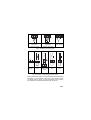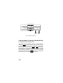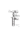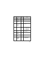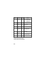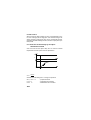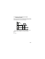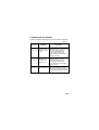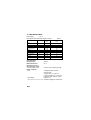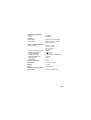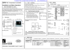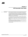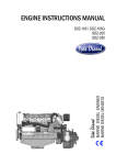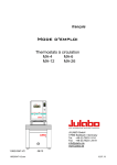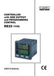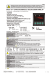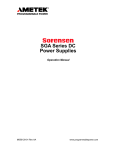
1
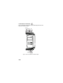
TEMPERATURE CONTROLLER MOUNTED ON A 35 mm RAIL RE60 TYPE USERS MANUAL 1 2 Contents 1. Application ................................................................................ 5 2. Controller set ............................................................................ 5 3. Preparing the controller for opereation .................................... 6 3.1. Security .............................................................................. 6 3.2. Controller installation ......................................................... 6 3.3. Electrical connections ....................................................... 7 3.4. Installation recommendations ........................................... 9 4. Starting to work ...................................................................... 10 5. Programming controller parameters ...................................... 11 5.1. Diagram of the controller menu ....................................... 11 5.2. List of controller parameters ............................................ 13 6. Control .................................................................................... 16 6.1. ON-OFF control ............................................................... 16 6.2. PID control ....................................................................... 17 7. Alarms ..................................................................................... 20 8. Auxiliary functions .................................................................. 21 8.1. Displaying the control signal ........................................... 21 8.2. Controller behaviour after sensor damage ..................... 21 8.3. Factory settings ............................................................... 21 9. Error signalling ........................................................................ 22 10. Technical data ....................................................................... 23 11. Ordering codes ..................................................................... 26 12. Maintenance and warranty ................................................... 26 3 4 1. APPLICATION The RE60 controller controls the temperature in objects through turning on and off the electrical controlling device according to the defined setting by the controller. It cooperates directly with RTD and TC. It is destined for the temperature control in telecommunication cabinets in food and drying industries and everywhere, where there is the necessity to stabilize the temperature changes. The controller has one output destined for the control and two alarm outputs. 2. ZESTAW REGULATORA r’s Use ual n ma Controller - 1 pc Plug - 2 pcs ty rran Wa rd ca Users manual - 1 pc Warranty card - 1 pc Quick start card - 1 pc When unpacking the controller, please check whether the type and version code on the data plate correspond to the order. 5 3. PREPARING THE CONTROLLER FOR OPERATION When unpacking the controller, please check whether the type and version code on the data plate correspond to the order. 3.1. Security The RE60 controller fulfils requirements concerning the security of electrical measuring automation instruments acc. to EN 61010-1 standard requirements concerning the resistance against electromagnetic noise acc. to EN 61000-6-2 standard and emission of electromagnetic noise occurring in the industrial environment acc. to EN 61000-6-4 standard. BASIC REQUIREMENTS, SAFETY INFORMATION Symbols located in this service manual mean: WARNING! Warning of potential, hazardous situations. Especially important. One must acquaint with this before connecting the instrument. The non-observance of notices marked by these symbols can occasion severe injuries of the personnel and the damage of the instrument ! ? CAUTION! Designates a general useful note. If you observe it, handling of the controller is made easier. One must take note of this, when the instrument is working inconsistently to the expectations. Possible consequences if disregarded ! In the security scope the RE60 controller meets the requirements of the EN 61010 -1 standard. 6 Remarks concerning the operator safety: 1. General - The instrument is destined to be mounted on a 35 mm rail - Non-authorized removal of the required housing, inappropriate use, incorrect installation or operation create the risk of injury to personnel or damage to equipment. For more detailed information, please study the present users manual. - All operations concerning transport, installation, and commissioning as well as maintenance must be carried out by qualified, skilled personnel and national regulations for the prevention of accidents must be observed. - According to this basic safety information, qualified,skilled personnel are personswho are familiar with the installation, assembly, commissioning, and operation of the product and who have qualifications necessary for their occupation. 2. Transport, storage Please observe the notes on transport, storage and appropriate handling. Observe the climatic conditions given in technical data. 3. Installation ? - The controller must be installed according to the regulation and instructions given in this users manual - Ensure proper handling and avoid mechanical stress. - Do not bend any components and do not change any insulation distances. - Do not touch any electronic components and contacts. - Instruments may content electrostatically sensitive components, which can easily be damaged by inappropriate handling. Do not damage or destroy any electrical components since this might endanger your heath! 7 4. Electrical connection - Before switching the instrument on, one must check the correctness of connection to the network. - In case of the protection terminal connection with a separate lead one must remember to connect it before the connection of the instrument to the mains. - When working on live instruments, the applicable national regulations for the prevention of accidents must be observed. - The electrical installation must be carried out according to the appropriate regulations (cable cross-sections, fuses, PE connection). Additional information can be obtained from the users manual. - The documentation contains information about installation in compliance with EMC (shielding, grounding, filters and cables). These notes must be observed for all CE-marked products. - The manufacturer of the measuring system or installed devices is responsible for the compliance with the required limit values demanded by the EMC legislation. 5. Operation - Measuring systems including RE60 controllers must be equipped with protection devices according to the corresponding standard and regulations for prevention of accidents. - After the instrument has been disconnected from the supply voltage, live components and power connections must not be touched immediately because capacitors can be charged. - The housing must be closed during operation. 6. Maintenance and servicing. - Please observe the manufacturers documentation and read all product-specific safety and application notes in this users manual. - Before taking the meter housing out, one must turn the supply off. - The removal of the instrument housing during the warranty contract period may cause its cancellation. When unpacking the controller, please check whether the type and version code on the data plate correspond to the order. 8 3.2. Controller installation ? Fix the controller on the 35 mm rail acc. to EN 60715. The controller housing is made of a self-extinguishing plastics. Dimensions of the controller and the fixing way is presented on the fig.1 41 45 93 120,7 35 120 RE60 lock 100 Fig.1. Dimensions and fixing way of the controller When unpacking the controller, please check whether the type and version code on the data plate correspond to the order. 9 3.3. Electrical connections ? Carry out electrical connections to the terminal strips and next insert strips into controller sockets. Supply WY1 A1 A2 9 10 11 12 13 14 15 16 1 2 3 4 5 6 7 8 Input signals Fig.2. View of controller connection strips 10 6 7 8 Pt100 Pt100 + 6 7 8 - 6 7 8 Pt100 resistance thermometer in a two-wire system Pt100 resistance thermometer in a three-wire system Thermocouple Fig.3. Connection of input signals - 9 10 - 11 12 - + SSR Supply Load + Supply Load Load Supply Load Supply 13 14 15 16 Output 1 - relay Alarm 2 - relay + 11 12 Supply Output 1 - relay Output 1 - logic voltage for SSR control Fig.4. Connection of the supply and load circuit When connecting the supply, one must remember that in the building installation a circuit-breaker should exist. This element should be placed near the device, be easy accessible for the operator and marked as the instrument disconnecting the device. 11 3.4. Installation recommendations In order to obtain a full fastness against electromagnetic noise in an environment with unknown noise level, it is recommended to observe following principles: - do not supply the controller from the network, in the proximity of devices generating high pulse noise and do not apply common earthing circuits, - apply network filters, - apply metallic shields in the shape of tubes or braids to conduct supplying wires, - wires leading measuring signals should be twisted in pairs, and for resistance sensors in 3-wire connection, twisted of wires of the same length , cross-section and resistance, and led in a shield as above, - all shields should be one-side earthed or connected to the protective wire, the nearest possible to the controller, - apply the general principle, that wires leading different signals should be led at the maximal distance between them (no less than 30 cm), and the crossing of these group of wires made at right angle (90o). 12 4. STARTING TO WORK After connecting the supply, what is signalled by the green diode, the controller displays the type and program version. RE60 ver1.00 After ca three seconds, the controller transits to the control acc. to set parameters. The controller displays the measured value, the set point and annunciators of connected outputs. The on-off control algorythm with hysteresis 2oC is set by the manufacturer. A character message informing about abnormalities can be shown on the display (tab. 2). Measured value (PV) 250.0C ÉÊË300.0 Set point Annunciator of the control output Annunciator Annunciator (SP) of alarm 1 of alarm 2 Change of the set point The entry into the set point change mode follows after pressing the or push-button. The way to change the set point is shown on the fig. 5. If the set point is not accepted within 30 seconds from the last pressure of the or push-button, the controller transits automatically into the normal working mode without the introduction of a new set point. 13 Beginning of changes or 250.0C 300.0 Acceptation of changes Cancellation of changes 250.0C SP 300.0 Increase the value Decrease the value Fig.5. Change of set point 5. PROGRAMMING OF CONTROLLER PARAMETERS 5.1. Diagram of the controller menu The controller service is presented on the fig.6. after pressing and push-button during at least 2 seconds, the proholding the gramming of parameters is possible. The transition between parameters is carried out by means of and push-buttons. Some parameters can be invisible - it depends on the choice of the control algorythm or the alarm configuration. The table 1 includes the description of parameters. The return to the normal working mode follows after pressing the push-button or automatically after 30 seconds from the last push-button pressure. 14 Monitoring of the control signal Normal working mode 250.0C É 53.8% 250.0C É 300.0 Start of changes Held up or Acceptation of changes Set point change mode 250.0C SP 300.0 Cancellation of changes Decrease of value Active access code T Increase of value 0 EnterSec N T Correct code? N 3sec Nex parameter Previous parameter 1-DP DecPoint SP Low SP High CtrlAlg Pb Ti Td To Hyst Out1 Out1Fail Al1-Type Al1-SP Al1-Dev Al1-Hyst Al1-Fail Al2-Type Al2-SP Al2-Dev Al2-Hyst Al2-Fail PV Shift Unit Security ReadOnly EnterSec Parameter change mode Start of changes Acceptation of changes Cancellation of changes 1-DP DecPoint Decrease of value or previous evaluated parameter Increase of value or next evaluated parameter Fig.6. Diagram of controller servicing menu 15 5.2. List of parameters The list of parameters in the menu is presented in the table 1. List of configuration parameters Parameter symbol Parameter description Factory setting Table 1 Range of parameter changes DecPoint Position of decimal point SPLow Lower limitation SP Min. measuring range Measuring range SPHigh Upper limitation SP Max. measuring range Measuring range CtrlAlg Control algorythm ON-OFF 1-DP 0-DP: 1-DP: without decimal point 1 decimal point ON-OFF: ON-OFFcontrol algorythm P: control algorythm P PD: control algorytm PD PID: control algorythm PID 16 Pb Proportional band1) 30.0 0.1...999.9 °C Ti Integration time-constant2) 300 1...9999 s Td Differentiation time-constant 3) 60.0 0.1...999.9 s Parameter symbol Parameter description Factory setting Range of parameter changes To Pulse repetition period 1) 20.0 0.5...99.9 s Hyst Hysteresis4) 2.0 0.2...99.9 °C Out1 Configuration of the control output INV DIR: direct control (cooling) INV: inverse control (heating) Signal control of output1 when sensor is damaged 0.0 0.0...100.0% AL1-Type Alarmu 1 typ NONE NONE: lack ABS-HI: absolute upper ABS-LO: absolute lower DEV-HI: relative upper DEV-LO: relative lower AL1-SP Set point of alarm 1 0.0 Measuring range AL1-Dev Deviation from set point for alarm 1 0.0 -199.9...199.9 °C AL1-Hyst Hysteresis for alarm 1 2.0 0.2...99.9 °C Alarm output state when the sensor is damaged OFF OFF: output turned off ON: output turned on Out1Fail AL1-Fail 17 Parameter symbol Parameter description Factory setting Range of parameter changes NONE: lack ABS-HI: absolute upper ABS-LO: absolute lower DEV-HI: relative upper DEV-LO: relative lower AL2-Type Alarm 2 type NONE AL2-SP Set point of alarm 2 0.0 Measuring range AL2-Dev Deviation from set point for alarm 2 0.0 -199.9...199.9°C AL2-Hyst Hysteresis for alarm 2 2.0 0.2...99.9 °C AL2-Fail Alarm output state when the sensor is damaged OFF OFF: output turned off ON: output turned on PVShift Shift of the measured value 0.0 -99.9...99.9°C Unit Unit oC NONE: without unit oC: degree centigrade Security Security code 0 0...9999 Parameter visible only for P, PD, PID. algorythms. Parameter visible only for PID algorythm. Parameter visible only for PD, PID algorythms. 4) Parameter visible only for ON-OFF algorythm . 1) 2) 3) 18 6. CONTROL 6.1. On-Off control When a high precision of the temperature control is not required, especially for objects with a high time-constant and a small delay, one can apply the on-off control with hysteresis. Advantages of this control way are the simplicity and reliability, however its defect is the oscillation formation, even at small hysteresis values. Output Hy On Off sp Measured value Fig. 7. Output operation way of heating type for the on-off control 19 6.2. PID control When we want to obtain a better accuracy of the temperature control, one must apply the PID algorythm. The controller tuning to the object consists on setting the value of the proportional element, integrating and differentiating elements, and the output pulse repetition period. 6.2.1. Selection of PID settings by the object identification method One must read out the object delay time To and the maximal temperature accretion speed from the dependence: 100 Y[%] 0 t [s] PV [°C] ∆t T0 ∆PV t [s] DPVmax Dt Calculate the PID settings acc. to the given equations: Pb=1.1 Vmax . T0 - proportional band ti=2.4 . T0 - integration time-constant td=0.4 . T0 - differentiation time-constant Vmax = 20 6.2.2. Selection of PID settings by the object identification method Set the on-off control with the minimal hysteresis. Set the set point on the normal work level (or on a lower level if overshoots could be cause damages) and on normal load conditions. PV P T t[s] 100% Y[%] t[s] Fig.8. Selection of settings by the object identification method Calculate controller settings acc. to the given equations: Pb = P ti = T td = 0.25 * T 21 6.2.3. Correction of PID settings The best is to choose parameters changing the value into a twice higher or twice lower. During the change, one must refer to following principles: a) Slow jump response: - decrease the proportional band, - decrease the integration and the differentiation time. b) Overshoots: - increase the proportional band, - increase the differentiation time. c) Oscillations: - increase the proportional band, - increase the integration time, - decrease the differentiation time. d) Instability: - increase the integration time. 22 7. ALARMS There are two alarm outputs in the controller. The signalling of any alarm is carried out through the lighting of the red LED diode. Moreover, there is information on the LCD display which alarm is active. Al-SP Absolute upper (ABS-HI) SP Al-Dev (-) Relative upper (DEV-HI) Al-SP Absolute lower (ABS-LO) Al-Dev (+) SP Relative lower (DEV-LO) Al-Dev (+) SP Relative upper (DEV-HI) SP Al-Dev (-) Relative lower (DEV-LO) Fig.9. Kinds of alarms The alarm configuration requires the selection of the alarm kind through the AL1-Type and AL2-Type. Accessible types of alarms are given on the fig.9. The set point for absolute alarms is the value defined by the AL1-SP, and AL2-SP parameter and for relative alarms it is the deviation from the set point in main circuit - AL1-Dev and AL2-Dev parameter. The alarm hysteresis, i.e. the zone around the set point, in which the output state is not changed, is defined by the AL1-Hyst and AL2-Hyst parameter 23 8. AUXILIARY FUNCTIONS 8.1. Displaying the control signal After pressing and holding the push-button, the value of the control signal (0.0...100%) is displayed on the lower display. 8.2. Controller behaviour after sensor damage It is possible to configure the output state after a sensor damage in the controller. The state for the output control is as follows: - at the output configuration to the proportional control (CtrlAlg¹ON-OFF) the value of the control signal is defined by the Out1Fail parameter - at the configuration to the on-off control (CtrlAlg=ON-OFF), the output will be turned off - at the output operation as heating, or turned on - at the output operation as cooling. The state of alarm output is set by AL1-Fail. and AL2-Fail. parameters 8.3. Factory settings One can restore factory setting during the supply turn on, holding and push-buttons till the moment when the message below appears on the upper display. Set Defaults 24 9. SIGNALLING OF ERRORS Character messages signalling the incorrect controller operation. Table 2 Error code (upper displ.) Reason Procedure Overflow of the measuring range downwards or lack of RTD Check, if the type of selected sensor is compatible witrh the connected one. Check if input signal values is contained in the suitable range - If yes, check if the RTD is not shorted or the thermocouple is not inversely connected. ErrPV-Hi Overflow of the measuring range or break in the sensor circuit Check, if the type of selected sensor is compatible witrh the connected one. Check if input signal values is contained in the suitable range - If yes, check if there is no break in the sensor circuit. Err.Cal Input discalibrated ErrPV-Lo Connect the controller supply again. When this does not help, contact the nearest authorized workshop service. 25 10. TECHNICAL DATA Input signals acc. 3 Input signals and measuring ranges for inputs Sensor type/inputs Pt100 acc.to EN 60751+A2 Pt100 Pt100 Fe-CuNi acc.to EN 60584-1 Fe-CuNi Fe-CuNi NiCr-NiAl acc.to EN 60584-1 NiCr-NiAl NiCr-NiAl PtRh10-Pt acc.to EN 60584-1 Marking Table 3 Range [°C] Basic error [°C] Pt100 Pt100 Pt100 -50...100 0...250 0...600 0.8 1.3 3.0 J J J 0...250 0...600 0...900 3.0 4.0 5.0 K K K 0...600 0...900 0...1300 4.0 5.0 6.0 S 0...1600 7.0 Current flowing through Pt100 220 mA Measurement time 0,5 s Detection of error in the measuring circuit: - thermocouple, Pt100 overflow of the measuring range Kinds of outputs: - relay - logic voltage (without isolation from the sensor side) 26 voltageless make contacts maximal load: voltage: 250 V a.c., 150 V d.c. current: 5 A 250 V a.c., 5 A 30 V d.c. resistance load: 1250 VA, 150 W napiêcie 5 V resistance limiting the current: 66 W Way of output operation: - reverse - direct Signalling: - active output - active alarm Rated operating conditions: - supply voltage for heating for cooling symbol on the LCD display symbol on the LCD display and LED diode - frequency of supply voltage - ambient temperature - storage temperature - related air humidity - external magnetic field - preheating time - work position 230 V a.c. ±10% 110 V a.c. ±10% 24 V a.c. ±10% 18...72 V d.c. 50/60 Hz 0...23...50 °C -20...+70 °C < 85 % (without condensation) < 400 A/m 30 min any Power consumption < 3 VA Dimensions 45 x 100 x 120 mm Weight < 0,3 kg Fixing on a 35mm rail Protection degree ensuring by the house IP40 acc. to EN 60529 27 Additional errors in rated operating conditions: - changes of the ambient temperature £100% of the basic error /10 K. Security requirements acc. to EN 61010-1 - installation category III - pollution level 2 - maximal phase-to-earth working voltage: - for the supplying circuit, outputs 300 V - for input circuits 50 V Electromagnetic compatibility: - immunity acc. to EN 61000-6-2 - emissions acc. to EN 61000-6-4 ORDERING EXAMPLE The RE60-05-1-2-3-0 code means: RE60 - Temperature controller of RE60 type to be mounted on a 35 mm rail 05 - input: thermocouple J 1 - main input: relay 2 - alarm outputs: 2 relays 3 - supply: 24 V a.c. 50/60 Hz 0 - without additional quality inspection requirements 28 11. ORDERING CODES The coding way is given in the table 4 Kinds of versions and ordering codes Temperature controller RE60 Input: resist. thermometer Pt100 resist. thermometer Pt100 resist. thermometer Pt100 thermocouple J thermocouple J thermocouple J thermocouple K thermocouple K thermocouple K thermocouple S as per order Table 4 XX X X X X (-50...100oC) ..... 01 (0...250oC) ........ 02 (0...600oC) ........ 03 (0...250oC) ........ 04 (0...600oC) ........ 05 (0...900oC) ........ 06 (0...600oC) ........ 07 (0...900oC) ........ 08 (0...1300oC) ...... 09 (0...1600oC) ...... 10 ........................ XX Main output: relay ..................................................................... 1 logic 0/5V for SSR control ................................... 2 as per order ......................................................... X Alarm outputs: bez wyjæ ...................................................................... 0 1 wyjcie przekanikowe .............................................. 1 2 wyjcia przekanikowe .............................................. 2 as per order ................................................................. X Supply 230 V a.c. 50/60 Hz ............................................................ 1 110 V a.c. 50/60 Hz ............................................................. 2 24 V a.c. 50/60 Hz .............................................................. 3 18...72 V d.c. ....................................................................... 4 as per order ........................................................................ X Additional requirements: without additional requirements ................................................. 0 with an extra quality inspection certificate .................................. 1 acc. to agreement with the user* ................................................ X * The code number is established by the manufacturer. 29 12. MAINTENANCE AND WARRANTY The RE60 controller does not require any periodical maintenance. In case of some incorrect operations: After the dispatch date and within the period stated in the warranty card: One should return the instrument to the Manufacturers Quality Inspection Dept. If the instrument has been used in compliance with the users manual, the Manufacturer warrants to repair it free of charge. The disassembling of the housing causes the cancellation of the granted warranty. After the warranty period: One should send the instrument to repair it in a authorized service workshop. Spare parts are available for the period of five years from the date of purchase. Our policy is one of continuous improvement and we reserve the right to make changes in design and specifications of any products as engineering advances or necessity requires and revise the above specifications without notice. 30 31 © LUMEL S.A., RE60-KZ1284/May 2006 Lubuskie Zak³ady Aparatów Elektrycznych - LUMEL S.A. ul. Sulechowska 1, 65-022 Zielona Góra, Poland Tel.: (48-68) 32 95 100 (exchange) Fax: (48-68) 32 95 101 www.lumel.com.pl e-mail:[email protected] Export Department: Tel.: (48-68) 329 53 02 or 53 04 Fax: (48-68) 325 40 91 e-mail: [email protected] 32