1
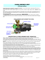
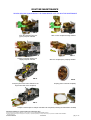
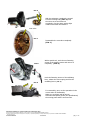
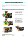
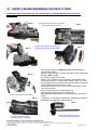
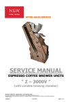
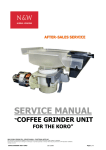
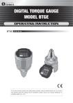
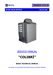
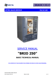
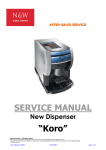
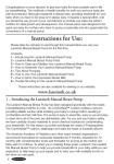
A
AFFT
TE
ER
R--S
SA
ALLE
ES
SS
SE
ER
RV
VIIC
CE
E
SERVICE MANUAL
H & C FUNCTIONAL UNITS
“SIGMA BREWER”
N&W GLOBAL VENDING SPA - SERVICE MANUAL-H&C FUNCTIONAL UNITS
This document was produced by MARK AC for the exclusive use of the N&W GLOBALVENDING personnel.
No part of this document may be divulged to a third party or reproduced partially or entirely without the prior permission of N&W GLOBAL VENDING .
. All rights reserved.
SIGMA BREWER
13/10/2005
pag. 1 / 12
SIGMA BREWER UNIT
(Filtered coffee)
Simple filtered coffee is obtained by natural “Percolation” of hot water through a special paper filter where a
ground coffee dose of approx 10 g is placed.
The ground coffee is coarser than the type used for espresso, and then a higher quality coffee, “Arabica” type is
used.
This operation, carried out using simple machines of a domestic type or similar, takes a considerable amount of
time, not compatible with the requirements of a vending machine, which must produce high quality but in a as
short a time as possible.
Therefore special brewing units are used, called simply “FRESH BREWER”
The Sigma Brewer unit can be used to obtain either a coffee brew or an infusion with tea leaves, simply by
replacing the filter with one more suitable to tea brewing; in some versions there are provisions also for a paper
filter.
SIGMA BREWER UNIT (PERSPECTIVE VIEW)
PUMPING CYLINDER
Brewing cylinder
Motor support
assembly and
mechanisms
Cylinder quick
extraction bracket
Brewer filter
Filter release
bracket for
maintenance
DESCRIPTION OF FRESH BREWER UNIT OPERATION
When a selection is made, the lower ratiomotor activates a worm screw, which by means of a slider drives a
system of levers, lifting the filter holder until closing the brewing cylinder in the lower side.
Then a gravity type solenoid valve, located on the boiler, opens and water starts flowing into the upper section of
the cylinder; the amount of water (dose) is pre-set via SW as length of time (the solenoid valve flow-rate is factory
preset).
After a few moments, the coffee doser device is started, conveying a dose of ground coffee, variable between 9
and 12 grams according to the time setting of the doser device (a 10 gram dose is set by default).
Immediately after dispensing powder and water, there is a programmable period defined as brewing time, with 0
to 5 second setting (this time is set to one second by default).
When increasing such time also the coffee extraction time increases, however it is necessary to balance between
quality and total time of the selection; in any case after 4 seconds the quality starts to decrease.
After the brewing phase, the upper ratiomotor is started and through a worm screw pushes the piston inside the
pumping cylinder, thus creating a pressure inside the brewing chamber that closes the valve located at the top of
the cylinder; in addition the same internal pressure created by the horizontal movement of the piston pushes and
at the same time stirs the water and coffee mixture through the lower filter, conveying it to the dispensing spout
and to the cup.
At the end of the stroke, the piston returns to the initial position and again repeats the cycle to completely empty
the coffee residue from the system. Then the first ratiomotor is started, opening the filter holder and a scraper
pushes the spent coffee dose outside the filter area, dropping it into the grounds container.
At this point, the system is re-positioned in stand-by until the next selection.
N&W GLOBAL VENDING SPA - SERVICE MANUAL-H&C FUNCTIONAL UNITS
This document was produced by MARK AC for the exclusive use of the N&W GLOBALVENDING personnel.
No part of this document may be divulged to a third party or reproduced partially or entirely without the prior permission of N&W GLOBAL VENDING .
. All rights reserved.
SIGMA BREWER
13/10/2005
pag. 2 / 12
The piston, the brewing chamber and the filter holder are fitted with vent valves (see description in the following
pages).
Water tightness between cylinder and lower filter is ensured by a special silicone seal on the filter holder, which
when closed is pushed against the filter holder cylinder, ensuring a 1 bar water tightness under standard
conditions.
To achieve an excellent FB filtered coffee, the following objective parameters must be kept constant:
1) COFFEE QUALITY AND AMOUNT AND ITS GRADE OF GRINDING
2) THE TEMPERATURE OF THE BOILER
3) BREWING AND DISPENSING TIME
4) WATER AMOUNT IN RELATION TO THE COFFEE DOSE
5) DRY RESIDUE
6) AMOUNT OF GROUNDS PASSING THROUGH THE FILTER
1)
COFFEE QUALITY AND AMOUNT & GRADE OF GRINDING
Mainly 100% ARABICA coffee is used for FB filtered coffee (or a blend with very small amounts of ROBUSTA
coffee). In Europe, generally already ground coffee is used with different grades of grinding, according to the
market and type of brew.
For FB coffee made in vending machines very finely ground coffee is used.
The ideal dose for FB coffee is 60 g / litre, i.e.: 10.8 g for 180 cc of water
10.2 g for 170 cc of water
Note: The water amount must be approximately 20 cc greater than the dispensed dose because of the water
absorption in the spent coffee powder.
2)
THE TEMPERATURE OF THE BOILER
The optimum water temperature is between 90° and 95° C, and it is very important to control the temperature
differential.
3) BREWING, DISPENSING AND DRYING TIME
Brewing time is determinant to achieve good quality, but being vending machines it is also necessary to control the
total time for the selection, obviously to reduce the waiting time.
Under normal conditions, such time can be adjusted between 3 and 8 sec; by default it is set to 3 sec.
Other than this time, the time necessary to fill the brewing chamber with water must be added, filled
simultaneously with the powder, permitting to start the brewing phase.
For the Necta unit this time is set to 14 sec.
After brewing, dispensing starts, with a time fixed to 5 sec, then at the end a 2 sec pause is necessary to allow the
spent coffee dose to dry.
A very long brewing time does not necessarily improve the dispensed drink quality: there is a time limit after which
the quality worsens.
4) WATER AMOUNT IN RELATION TO THE COFFEE DOSE
As already mentioned, the ideal amount is 60 g / litre, there are however situations where coffee is dispensed in
amounts of 120 g / litre (strong coffee).
5) DRY RESIDUE (coffee extraction)
The optimum dry residue is between 1.30 and 1.60% of the extracted substances.
Coffee extraction must be between an optimum range of 18 and 22%.
6) THE AMOUNT OF GROUNDS PASSING THROUGH THE FILTER
Grounds must not be greater than 75 mg / 100 cc.
N&W GLOBAL VENDING SPA - SERVICE MANUAL-H&C FUNCTIONAL UNITS
This document was produced by MARK AC for the exclusive use of the N&W GLOBALVENDING personnel.
No part of this document may be divulged to a third party or reproduced partially or entirely without the prior permission of N&W GLOBAL VENDING .
. All rights reserved.
SIGMA BREWER
13/10/2005
pag. 3 / 12
EXPLODED VIEW OF SIGMA BREWER UNIT
Ratiomotor assembly
Piston control
Air pumping
Oscillating levers
assembly for controlling
filter holder closing
Piston
Pumping
cylinder
Compression
valve
Ratiomotor assembly for
controlling spent coffee
scraper and filter holder
Brewing chamber
assembly
Filter holder
assembly
Carriage assembly for sliding
scraper and controlling filter
holder
Filter cleaning brush
N&W GLOBAL VENDING SPA - SERVICE MANUAL-H&C FUNCTIONAL UNITS
This document was produced by MARK AC for the exclusive use of the N&W GLOBALVENDING personnel.
No part of this document may be divulged to a third party or reproduced partially or entirely without the prior permission of N&W GLOBAL VENDING .
. All rights reserved.
SIGMA BREWER
13/10/2005
pag. 4 / 12
ROUTINE MAINTENANCE
PROCEDURES FOR DISASSEMBLING THE SIGMA BREWER UNIT FOR ROUTINE MAINTENANCE
FIG. 1
FIG. 2
Press the extraction grip jaws
(green) and pull outwards
Slide out the complete brewing chamber
FIG. 4
FIG. 3
Grasp the pumping chamber, lift
slightly and pull outwards
Slide out completely the pumping chamber
FIG. 5
FIG. 6
Grasp the piston and rotate clockwise a few
degrees and slide it out completely
Pumping piston removed completely
FIG. 7
FIG. 8
Grasp the external pincers and pull outwards until completely removing the filter holder assembly
N&W GLOBAL VENDING SPA - SERVICE MANUAL-H&C FUNCTIONAL UNITS
This document was produced by MARK AC for the exclusive use of the N&W GLOBALVENDING personnel.
No part of this document may be divulged to a third party or reproduced partially or entirely without the prior permission of N&W GLOBAL VENDING .
. All rights reserved.
SIGMA BREWER
13/10/2005
pag. 5 / 12
EXTRAORDINARY MAINTENANCE
Procedures for disassembling the SIGMA BREWER unit for extraordinary maintenance (to be carried out in the
event of malfunctions and preventative maintenance- see description in the following sections)
REMOVAL OF RATIOMOTOR ASSEMBLY CONTROLLING SCRAPER HOLDER AND FILTER HOLDER
FIG. 1
FIG. 2
Remove the complete SIGMA BREWER unit from the machine
(SEE DESCRIPTION IN THE RELEVANT SERVICE MANUAL)
Turn the unit upside down and undo the ratiomotor assembly fastening screws with a special key – (FIG. 1)
Free and remove completely the ratiomotor, manually rotating the worm screw until removing it completely from
the threaded bush - ( FIG. 2)
FIG. 3
FIG. 4
Place the brewer unit on a flat surface and
undo the two side screws using a special key (FIG. 3)
Turn the unit upside down and undo the two
fastening screws of the ratiomotor - (FIG. 4)
Release the motor, slightly forcing the two side
metal-sheeting supports to release the right
angle ribs and completely remove the
ratiomotor - (FIG. 5)
FIG. 5
N&W GLOBAL VENDING SPA - SERVICE MANUAL-H&C FUNCTIONAL UNITS
This document was produced by MARK AC for the exclusive use of the N&W GLOBALVENDING personnel.
No part of this document may be divulged to a third party or reproduced partially or entirely without the prior permission of N&W GLOBAL VENDING .
. All rights reserved.
SIGMA BREWER
13/10/2005
pag. 6 / 12
FIG. 6
With the ratiomotor completely removed
from the brewing body (FIG. 6) undo
the worm screw and remove it
completely, free the piston with a slight
rotation movement and extract it
Vent valve
FIG. 7
Disassemble the vent valve completely
(FIG. 7)
FIG. 8
FIG. 9
With a special tool, undo the two fastening
screws of the position sensor and remove it
completely - (FIG. 8)
Undo the fastening screws of the oscillating
lever, release the return spring and free the
oscillating levers ( FIG. 9)
For reassembly, carry out the operations in the
reverse order of disassembly.
Make sure to tighten well all screws
Lubricate with special grease (see specifications)
the moving parts and the worm screws.
N&W GLOBAL VENDING SPA - SERVICE MANUAL-H&C FUNCTIONAL UNITS
This document was produced by MARK AC for the exclusive use of the N&W GLOBALVENDING personnel.
No part of this document may be divulged to a third party or reproduced partially or entirely without the prior permission of N&W GLOBAL VENDING .
. All rights reserved.
SIGMA BREWER
13/10/2005
pag. 7 / 12
SCHEDULED MAINTENANCE OPERATIONS
The SIGMA BREWER unit is very efficient and reliable; however, in order to maintain the initial features
unchanged and for obtaining coffee dispensing always of excellent quality, scheduled maintenance at regular
intervals is necessary.
The planned maintenance time intervals are only a guideline, as they depend on the type of coffee and on other
external factors.
1) EVERY 1000 COFFEES OR ONCE A WEEK
Cleaning the brewing cylinder and piston, cleaning the lower filter – (Expected time 2 minutes)
Press the green pincers (FIG.1) and
at the same time pull gently the
brewing cylinder assembly until
releasing it completely (FIG. 2)
Slightly force upwards and at the
same time pull outwards the blowing
cylinder. (FIG. 3 – FIG. 4)
Disassemble the two parts of the
lower cylinder with a rotating and
pulling movement. (FIG. 5)
Completely remove the filter holder.
(FIG. 6)
Thoroughly wash the disassembled
parts with drinking water; in the
event of persistent scaling use
special detergents.
Air dry thoroughly, check the state of
the filter and of seals (if necessary
replace with original components)
FIG. 1
FIG. 4
FIG. 2
FIG. 3
FIG. 6
N&W GLOBAL VENDING SPA - SERVICE MANUAL-H&C FUNCTIONAL UNITS
This document was produced by MARK AC for the exclusive use of the N&W GLOBALVENDING personnel.
No part of this document may be divulged to a third party or reproduced partially or entirely without the prior permission of N&W GLOBAL VENDING .
. All rights reserved.
SIGMA BREWER
13/10/2005
pag. 8 / 12
2) EVERY 5000 COFFEES OR ONCE A MONTH
Replacing or cleaning the filter and filter holder (Total expected time 3 minutes)
Remove the brewing chamber as described in the
previous section.
Press on lever A and at the same time pull hard the
lower filter holder until removing it completely (FIG. 1,
2 & 3)
Remove the gasket, lifting it by the special edge (FIG.
4) and remove the filter.
FIG. 1
Inspect the state of the filter and its gasket. (FIG. 5)
In the event of a filter completely clogged with scaling,
or torn or signs of damage, replace filter and gasket.
(FIG. 5)
A
If in good state, or with very little scaling, wash,
descale and reassemble all parts in the reverse order of
disassembly.
Scaling reduces the size of the filtering holes, reducing
its efficiency and worsening the quality of coffee
FIG. 2
N.B.: A filter that is too clogged with scaling makes
brewing slow and difficult with the risk of leaking
product along the seal.
A filter that is too worn, allows the passage of coffee
grounds into the cup, reducing the quality of the brew.
FIG. 3
FIG. 5
FIG. 4
N&W GLOBAL VENDING SPA - SERVICE MANUAL-H&C FUNCTIONAL UNITS
This document was produced by MARK AC for the exclusive use of the N&W GLOBALVENDING personnel.
No part of this document may be divulged to a third party or reproduced partially or entirely without the prior permission of N&W GLOBAL VENDING .
. All rights reserved.
SIGMA BREWER
13/10/2005
pag. 9 / 12
3) EVERY 150.000 BREWINGS OR ONCE A YEAR
Opening the unit and checking for worn internal parts, cleaning and lubrication of various
components.
.
FIG. 1
.3
3FIG. 1
Undo the ratiomotor support, controlling
the blowing piston movement
FIG. 2
Remove the ratiomotor controlling the
blowing piston and remove the piston
FIG. 3
FIG. 2
FIG. 5
Seeger
Remove the position control sensor
FIG. 6
FIG. 4
Follow the procedures of pages 5, 6, & 7 disassembling the
unit's functional parts.
Analyse each component, checking the state of wear, scaling and
function. (FIG. 1 - 12)
if necessary, replace critical parts.
Descale, rinse, lubricate the moving parts, using specific foodsafe grease for parts in contact with foodstuff, while for all other
moving parts and for the worm screw special grease as indicated
in the enclosed specifications can be used.
Reassemble all parts in the reverse order of disassembly; make
some test selections.
Enter the operation in the special HACCP log
Use exclusively original parts for replacement.
With adequate maintenance the unit was tested to last 300,000
cycles *
(* this figure is a guideline, reached after adequate preventative
maintenance and depends on many factors)
FIG. 7
Remove the ratiomotor support,
controlling the slide movement
Undo the ratiomotor support,
controlling the slide movement
N&W GLOBAL VENDING SPA - SERVICE MANUAL-H&C FUNCTIONAL UNITS
This document was produced by MARK AC for the exclusive use of the N&W GLOBALVENDING personnel.
No part of this document may be divulged to a third party or reproduced partially or entirely without the prior permission of N&W GLOBAL VENDING .
. All rights reserved.
SIGMA BREWER
13/10/2005
pag. 10 / 12
FIG. 8
Check the state of the mechanisms
and verify the correct movement of
the slides and oscillation of the levers
FIG. 9
Disassemble the upper section of the
brewing chamber, check the state of
the chamber closing valve.
FIG. 10
Completely disassemble the filter and
check the level of clogging
B
FIG. 11
FIG. 12
Check the correct operation of
the filter one-way valve
Check the correct
operation of the
depression valve
N&W GLOBAL VENDING SPA - SERVICE MANUAL-H&C FUNCTIONAL UNITS
This document was produced by MARK AC for the exclusive use of the N&W GLOBALVENDING personnel.
No part of this document may be divulged to a third party or reproduced partially or entirely without the prior permission of N&W GLOBAL VENDING .
. All rights reserved.
SIGMA BREWER
13/10/2005
pag. 11 / 12
4) TROUBLE-SHOOTING
RATIOMOTOR: OPENING THE BREWING
CYLINDER AND SCRAPING THE FILTER
A
1) The unit does not find the standby position and the
machine is locked out by the software.
--------------------------------The slide movement ratiomotor for opening the brewing
cylinder and scraping the filter is controlled by the operation
time in tenths of a second for the functioning and by current
absorption on the motor torque in the event of blockage.
Check that the machine board is in working order, otherwise
replace with one certain of working properly and verify that
the problem is solved.
In the event the problem is not solved, replace the ratiomotor
with a new one.
2) The filter holder does not find the standby position
and the machine is locked out by the software.
--------------------------------> As above < The system is activated by the same
ratiomotor; also check that the mechanism slides freely and
does not create struggling to the motor, causing the triggering
of the protection device.
---------------------------------
RATIOMOTOR: CONTROLLING BLOWING
PISTON AND POSITION SENSOR
BREWING CYLINDER AND ONE-WAY VALVE
LOWER FILTER BEING REMOVED
PUMPING PISTON
AND RETURN VALVE
LOWER FILTER HOLDER
AND ONE-WAY VALVE
3) The air pumping piston ratiomotor does not start, or
it stops in an inadequate position.
--------------------------------Check that the protection system was not triggered, checking
the torque in mA.
The piston position is determined by the rotation movement of
the worm screw, which is controlled by a sensor that counts
the number of rotations; therefore verify the correct
functioning and if necessary replace with one certain of
working properly.
4) The piston, although moving correctly, does not
create the pumping effect, or during its return draws
water and coffee from the filter.
--------------------------------Check the functioning of the upper valve in the brewing
chamber, during the piston stroke it must close the chamber
perfectly; verify that the vent valve of the pumping piston
works correctly
5) The brewed coffee comes out slowly from the spouts
and overflows from the closing gasket of the brewing
cylinder
--------------------------------Check the state of clogging of the filter and of the gasket; if
necessary replace.
6) During the return of the blowing piston, coffee is
sucked in from the filter holder.
--------------------------------Check the functioning of the two valves located on the piston
and on the filter holder; they must not be dirty with scaling or
clogged.
N&W GLOBAL VENDING SPA - SERVICE MANUAL-H&C FUNCTIONAL UNITS
This document was produced by MARK AC for the exclusive use of the N&W GLOBALVENDING personnel.
No part of this document may be divulged to a third party or reproduced partially or entirely without the prior permission of N&W GLOBAL VENDING .
. All rights reserved.
SIGMA BREWER
13/10/2005
pag. 12 / 12