1
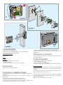
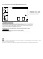
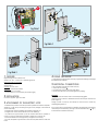
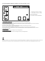
Manuel d’installation et d’utilisation
SERRURE ELECTRIQUE
DE SECURITE
XO 403+tel
V.09-2014 ::: Ind. A
FR
2
B
12 mm
4
12 mm
2
4
2
3
3
2
2
1
1
A
E
1
Fig/Abb.1
C
D
F
Fig/Abb 2
E
1
Fig/Abb 4
Fig/Abb 3
caracteristiques
Serrure électrique ouverture à droite.
Déclenchement par impulsion électrique ou clé ou télécommande
Fonctionne sur 8-12 V continu ou alternatif.
Consommations réduites:
700 mA sous 12V
500 mA sous 8V
Tension:
12-V AC ou DC
Important:
Section des fils à raccorder sur les 2 bornes:
. 1 à 25 m : 2 fils de 6/10
. au-delà de 25 m: 2 fils de 1,5 mm2 (sur toute la longueur).
2
installation
3
fixation de la serrure electrique
D’origine la serrure est montée «droite».
F
• Refermer le boîtier de la serrure électrique à l’aide des 2 vis (F)
• Visser le support plastique et refermer avec le cache plastique pour
masquer les vis.
4
fixation de la gâche fixe
5
câblage électrique
• Fixer la gâche fixe à l’aide des 3 vis fournies (E) en respectant la hauteur
notée dans le gabarit.
• Passer les câbles par le trou « passe câble « (A).
• Dévisser légèrement les 2 vis 1 .2 3 34 35
• Coincer le premier fil entre les 2 lamelles.
• Répéter l’opération pour le deuxième fil (aucune polarité à respecter).
Remarque importante :
Cette serrure ne peut pas être utilisée sur un portail s’ouvrant vers l’extérieur.
Distance à respecter entre la gâche et la serrure de 9 mm environ (côte
F , figure 4).
En cas de panne d’électricité, la clé peut toujours être utilisée et il n’y a
donc aucun problème pour rentrer chez soi.
• Déterminer l’emplacement de l’étrier et le trou de passage du cylindre avec
Si vous voulez tester ou essayer votre serrure alors qu’elle n’est pas installée,
le gabarit joint.
vous devez absolument simuler la présence de la gâche en appuyant sur
Attention, prévoir l’espace suffisant pour le passage de l’antenne du
le penne de mémorisation
récepteur (B).
1( 2 ,3Fig.
4 3
3
51), afin d’activer la mémoire mécanique.
• Fixer le support sur le portail à l’aide des 4 vis fournies(C).
• Fixer la serrure électrique sur le support à l’aide des 4 vis (D)
• Positionner le support plastique pour l’antenne autour du cylindre, venir
enrouler le câble antenne à l’intérieur (un seul tour suffit)(C).
6
programmation telecommande serrure électrique
-/~ +/~
J1
- / ~: Alimentation, 12Vac or –12Vdc;
+ / ~: Alimentation, 12Vac or +12Vdc;
J5 Connecteur serrure électrique
Ext_ctrl: Contact alimenté portier
J5
+
EXT CTRL
J3
P2
P1
DL1
1 - PROGRAMMATION OUVERTURE SERRURE
a) En mode monostable (un appui sur la télécommande déclenche l’ouverture, la fermeture se fait automatiquement).
Appuyer 1 fois et relâcher le bouton P1 pour programmer en mode monostable.
Le voyant DL1 s’allume, simultanément appuyer la touche souhaitée de votre télécommande pour réaliser l’ouverture.
b) En mode bi - stable (un appui sur la télécommande déclenche l’ouverture , un second appui permet la fermeture.
Appuyer sur P1 3 fois puis relâcher, pour programmer en mode bistable.
Le voyant DL1 s’allume, puis simultanément appuyer sur la touche souhaitée sur votre télécommande pour réaliser
l’ouverture et la fermeture. Ensuite, le voyant DL1 s’éteint, la programmation est terminée.
Si la programmation échoue : DL1 se rallume pendant 10 secondes. Vous devrez recommencer l’opération.
2 - DEPROGRAMMATION
Appuyer sur P2 une fois puis relâcher.La led s’allume, la touche est déprogrammée.
3 - DEPROGRAMMATION COMPLETE
Appuyer sur P2 pendant 10 secondes, puis relâcher. La led s’allume, toutes les touches sont déprogrammées.
Ne jetez pas les piles et les appareils hors d’usage avec les ordures ménagères. Les substances dangereuses qu’ils sont susceptibles de contenir
peuvent nuire à la santé et à l’environnement.
Faites reprendre ces appareils par votre distributeur ou utilisez les moyens de collecte sélective mise à votre disposition par votre commune.
Installation and operation manual
ELECTRIC SAFETY
LOCK
XO 403+tel
V.09-2014 ::: Ind. A
EN
2
B
12 mm
4
12 mm
2
4
2
3
3
2
2
1
1
A
E
1
Fig/Abb.1
C
D
F
Fig/Abb 2
E
1
Fig/Abb 4
Fig/Abb 3
features
Right opening function electric lock.
Works on 8 – 12 V ~ continuous or alternating current.
Reduced power consumption:
700 mA at 12 V~
500 mA at 8 V~
Voltage: 12-V AC or DC
Important: Terminal wire calibre:
• 1-25 metres: 2 x 6/10 wires,
• over 25 metres: 2 x1.5 mm2 wires (the whole length).
2
installation
3
attachment of the electric lock
The lock is supplied “right” mounted.
• Determine the position of the stirrup and the cylinder hole with the template.
Attention, to plan the space being enough for the passage of the antenna
of the receiver (B)
• Using the four screws supplied, fix the carrier to the gate. (C)
• Using the four screws, fix the electric lock to the carrier (D).
• To position the support blows up for the antenna around the cylinder, to
come to roll up the cable antenna inside (a single tour is enough). (E)
• Close the electric lock housing back up using the two screws (F).
• To screw the plastic support and to close with the plastic mask to mask saw
them.
4
fixing the keeper
5
electrical connections
F
• Fix the keeper using the three screws (E) supplied according to the height
stipulated in the template.
• Pass the cables through the correct hole (A).
• Loosen the two screws 1 .2 3 34 35
• Fix the first wire between the two small plates.
• Do the same with the second wire (ignore the polarity).
Important:
This type of lock cannot be used on outward-opening gates.
Leave a space of about 9 millimetres between the keeper and the lock
(side F, figure 4).
During a power cut, the key can always be used so there is never any
problem getting back in.
If you want to test your lock before it is installed, the presence of the keeper
3 3
4 3
5
must always be simulated by pressing on the memorisation flap1( 2 ,Fig.
1)
to activate the mechanical memory.
6
programming remote controls for the electric lock
-/~ +/~
J1
J5
+
EXT CTRL
- / ~: Power input, 12Vac or –12Vdc;
+ / ~: Power input, 12Vac or +12Vdc;
J5 Lock coil connector
Ext_ctrl: Input for remote doorphone
J3
P2
P1
DL1
1 - PROGRAMMING OPENING LOCK
a) In monostable mode (press on the remote control start the opening, the lock is automatically made).
Press 1 time and release the button P1 to program in monostable mode. The light DL1 ignites, simultaneously to press the key wished by
your remote control to realize the opening.
b) In mode bi - stable (a support on the remote control start the opening, a second support allows the lock.
Press on P1 3 time may release, to program in bistable mode.
The led DL1 lights, then press simultaneously on the key wished on your remote control to realize the opening and the lock.
Then, the Led DL1 goes out, the programming is ended. If the programming fails: DL1 flares up again during 10 seconds. You will have
to begin again the operation.
2 - DEPROGRAMMING
Press on P2 once then to release. The led lights, the key is deprogrammed.
3 - COMPLETE DEPROGRAMMING
Press on P2 during 10 seconds, then to release. The led lights, all the keys are deprogrammed.
Don’t throw batteries or out of order products with the household waste (garbage). The dangerous substances that they are likely to include may
harm health or the environment. Make your retailer take back these products or use the selective collect of garbage proposed by your city.