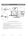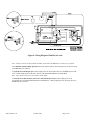
1
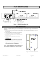
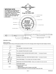
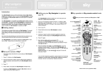
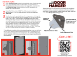
DOR-O-MATIC®
AUTOMATIC DOOR SYSTEMS
BBU250
Installation Instructions
And Service Manual
94015-900 Battery Back-Up
DOR-O-MATIC®
AUTOMATIC DOOR SYSTEMS
7350 West Wilson Avenue
Harwood Heights, IL 60706-4708
1-800-543-4635
708-867-7400
Engineering Fax: 708-867-1177
www.doromatic.com
94015-984 Rev. B
October 2003
INDEX
BBU250
94015-900 Battery Back-Up
PAGE
TITLE
COVER PAGE
1
INDEX
2
GENERAL
IMPORTANT INFORMATION
3
PART IDENTIFICATION
INSTALLATION
4
WIRING SET-UP
5
WIRING DIAGRAMS
6-7
WALK-THROUGH TEST
SERVICE
94015-984 Rev. B
8
October 2003
Page 2 of 8
GENERAL
The BBU250 Battery Back-Up 94015-900 provides reliable and uninterrupted power to the 96K Sliding Door System in the
event of main AC power loss. The included batteries are automatically fast and/or trickle charged by the BBU250 when
connected to the 96K Controller 84657-900. Audible and visual indicators report the status of the unit.
The BBU250 may be field-wired in one of three ways to achieve the following functionality:
1. Door and sensors continue to operate normally (dependent on battery charge and door usage). A fully charged
BBU250 should operate a standard bi-parting package and all 24V accessories for approximately 250 cycles.
2. Door opens and remains in the open position.
3. Door closes after all safety sensors are clear and remains in the closed position.
IMPORTANT INFORMATION
•
•
•
•
•
•
CAUTION: To reduce the risk of fire, connect only to a circuit provided with overcurrent protection in accordance
with the National Electrical Code ANSI/NFPA. Equipment must be connected to ground.
If the equipment has an internal energy source (the battery), the output may be energized when the unit is not connected
to the 96K Controller.
To de-energize: place the remote switch in the “OFF” position and/or place the battery power lever in the “DOWNOFF” position. Next, disconnect the unit from the 96K Controller. Finally, disconnect the battery.
Do not attempt to disassemble the unit; the unit has no user serviceable parts.
Used batteries must be recycled. Deliver used batteries to an appropriate recycling facility.
The connectors on the BBU250 are designed to mate with the 96K II Controller 84657-900. To use the BBU250 with
the 96K Controller 96010-900, adapter harness 84775-600 is required.
94015-984 Rev. B
October 2003
Page 3 of 8
PART IDENTIFICATION
BBU250
Dor-O-Matic
Figure 1: BBU250 Battery Back-Up
INSTALLATION
Important: Verify that main AC power to the 96K Sliding Door System is shut off to prevent unintended door
movement.
1. Locate a convenient place in the header to mount the BBU250. It is recommended to locate the unit close to the
96K Controller.
2. Using a drill or chisel, create an entry point in the header
extrusion channel (Figure 2) for the attaching bolts.
3. Insert the M6 bolts (included) into the channel and slide to
the desired location.
4. Attach the BBU250 to the header with the M6 nuts
(included).
5.
6.
OPTIONAL STEPS
Locate a convenient place on the jamb to mount the OFFON key switch (84222-900). It is recommended to locate
the key switch on the jamb closest to the BBU250.
Prepare the jamb using the template provided with the key
switch, route the cable into the header, and mount the key
switch to the jamb with the included hardware.
NOTE: When wiring the header, place the main power in
one wire channel and the accessory wiring in the other.
Figure 2: Header Extrusion Channel
94015-984 Rev. B
October 2003
Page 4 of 8
WIRING SET-UP
CAUTION: Do NOT attach plug to output power connector J2 on the BBU250 until after wiring set-up is complete.
Note: Refer to the appropriate wiring diagram for complete wiring details.
1. Ensure that power has been removed from the 96K Controller.
2. Verify red (+) battery lead is connected to terminal J1-8 and black (-) battery lead is temporarily connected to
terminal J1-6 on the BBU250.
3. Remove jumper wire from J1-1 & J1-2 on the BBU250 to temporarily disable audible (buzzer) alert.
4. If optional OFF-ON key switch (84222-900) is used, cut off connector plug from OFF-ON key switch cable, strip
wire ends, and connect to J1-3 & J1-4 on the BBU250. Verify key switch is in OFF position.
5. Disconnect the 4-pin transformer secondary plug from connector J7 on the 96K Controller PCB.
6. Connect the input power plug of the BBU250 to the 4-pin transformer secondary plug on the 96K Controller.
7. Connect the earth ground wire to the designated mounting screw on the 96K Controller PCB.
8. Connect the output power plug from J2 of BBU250 to connector J7 on the 96K Controller PCB.
9. Determine which accessories are to be powered by the BBU250 and which accessories are to be powered by the
96K Controller. Note: Only accessories rated for 24VDC should be connected to the BBU250 at J2-4 & J2-5 as
required.
a. For continuous, uninterrupted operation of the door and accessories, connect input power for all
accessories to the BBU250 at J2-4 & J2-5.
b. To open the door and keep it open, connect input power for all activation devices to the BBU250 at J2-4 &
J2-5. Connect input power for all safety devices to the Pencil Beam Bracket Terminal Block. Note:
safety devices must be set for normally closed output.
c. To close the door (after all safety sensors are clear) and keep it closed, connect input power for all
activation devices to the Pencil Beam Bracket Terminal Block. Connect input power for all safety
devices to the BBU250 at J2-4 & J2-5.
10. Carefully remove black (-) battery lead from J1-6 and connect to J1-9 on the BBU250.
11. Re-install the 96K Controller.
12. Connect jumper wire to J1-1 & J1-2 if audible (buzzer) alert is required.
13. Dress all wires and cables to allow proper door movement.
14. Perform walk-through test.
94015-984 Rev. B
October 2003
Page 5 of 8
WIRING DIAGRAMS
Figure 3: Wiring Diagram Without Electric Lock
Note: Only accessories rated for 24VDC should be connected to the BBU250 at J2-4 & J2-5 as required.
For continuous, uninterrupted operation of the door and accessories, connect input power for all
accessories to the BBU250 at J2-4 & J2-5.
To open the door and keep it open, connect input power for all activation devices to the BBU250 at J2-4 &
J2-5. Connect input power for all safety devices to the Pencil Beam Bracket Terminal Block.
Note: safety devices must be set for normally closed output.
To close the door (after all safety sensors are clear) and keep it closed, connect input power for all
activation devices to the Pencil Beam Bracket Terminal Block. Connect input power for all safety devices to
the BBU250 at J2-4 & J2-5.
94015-984 Rev. B
October 2003
Page 6 of 8
Figure 4: Wiring Diagram With Electric Lock
Note: Only accessories rated for 24VDC should be connected to the BBU250 at J2-4 & J2-5 as required.
For continuous, uninterrupted operation of the door and accessories, connect input power for all accessories
to the BBU250 at J2-4 & J2-5.
To open the door and keep it open, connect input power for all activation devices to the BBU250 at J2-4 &
J2-5. Connect input power for all safety devices to the Pencil Beam Bracket Terminal Block.
Note: safety devices must be set for normally closed output.
To close the door (after all safety sensors are clear) and keep it closed, connect input power for all
activation devices to the Pencil Beam Bracket Terminal Block. Connect input power for all safety devices to
the BBU250 at J2-4 & J2-5.
94015-984 Rev. B
October 2003
Page 7 of 8
WALK-THROUGH TEST
1.
2.
3.
4.
5.
6.
7.
Turn on main AC power to the 96K Sliding Door System.
Verify that the sliding door system is operating properly. Perform all necessary adjustments and tests. Refer to the
96K instruction manuals for more details.
Once the 96K Control Box is operating properly, place the optional OFF-ON key switch in the ON position or
insert a jumper wire across J1-3 & J1-4 on the BBU250. The BBU250 should now be ready for operation.
While sliding door is in normal operation, abruptly turn off main AC power to the sliding door system. All door
operation should remain unaffected.
Verify that the audible (buzzer) alert and red LED indicator is functioning. Buzzer will sound continuously and
LED indicator will illuminate continuously when AC power failure occurs. Check buzzer volume with header
access cover completely closed. Note: If audible alert is not required, remove jumper wire from J1-1 & J1-2.
Continue to operate sliding door system and verify proper BBU250 operation. If door shows sluggish movement,
halts, or loses control, battery may be undercharged.
Reapply main AC power to the sliding door system. Audible (buzzer) alert and red LED indicator should shut off.
SERVICE
•
When servicing the 96K Sliding Door System, verify that main AC power is shut off and that the OFF-ON key
switch for the BBU250 is in the OFF position. This will prevent any unintended door movement.
•
The battery power lever may also be used to disable the BBU250. Pull lever down to disconnect battery power at
BBU250 terminal J2. Lever should only be used when main AC power is shut off.
•
Battery level should be 23-27 VDC to properly operate door system during AC power failure. Allow 24 hours for
charging when battery level reaches 21 VDC or lower.
•
Do not attempt to disassemble the unit; the unit has no user serviceable parts.
If, after troubleshooting a problem, a satisfactory solution cannot be achieved, please call
Dor-O-Matic Technical Support at 1-888-942-9945 for further assistance.
DO NOT leave any problem unresolved. If you must wait for the following workday to call, leave the door inoperable
until satisfactory repairs can be made. NEVER sacrifice the safe operation of the automatic door or gate for an
incomplete solution.
94015-984 Rev. B
October 2003
Page 8 of 8