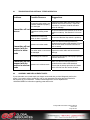
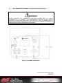
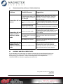
1
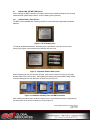
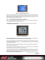
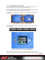
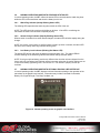
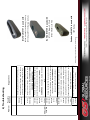
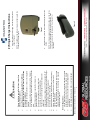
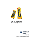
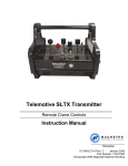
Enrange MBT Transmitter Remote Equipment Controls March 2013 Part Number: 178-01636-0100-R3 © 2013 Magnetek Material Handling Your New Radio Remote Thank you for your purchase of Magnetek’s Enrange® brand MBT Radio Remote Equipment Control. Magnetek has set a whole new standard in radio-remote performance, dependability, and value with this unique line of handheld transmitters. If your product ever needs modification or service, please contact one of our representatives at the following locations: U.S. Service Information For questions regarding service or technical information contact: 1.866.MAG.SERV (1.866.624.7378) World Headquarters: Magnetek, Inc. N49 W13650 Campbell Drive Menomonee Falls, WI 53051 Telephone: Website: e-mail: 1.800.288.8178 www.magnetekmobilehydraulic.com [email protected] Fax Numbers: Main: 1.800.298.3503 Sales: 1.262.783.3510 Service: 1.262.783.3508 Magnetek, Inc. has additional satellite locations for Canada and the United States. For more information, please visit http://www.magnetekmobilehydraulic.com. ©2013 MAGNETEK All rights reserved. This notice applies to all copyrighted materials included with this product, including, but not limited to, this manual and software embodied within the product. This manual is intended for the sole use of the person(s) to whom it was provided, and any unauthorized distribution of the manual or dispersal of its contents is strictly forbidden. This manual may not be reproduced in whole or in part by any means whatsoever without the expressed written permission of MAGNETEK. Enrange MBT Transmitter Instruction Manual March 2013 Page 2 of 45 8.1 TROUBLESHOOTING OPTIONAL TETHER OPERATION Problems Possible Reasons Suggestions Connecting tether cable is not installed, installed improperly, or is damaged. Inspect the tether cable and confirm that it is installed and secured correctly. Inspect all connectors, connector contacts and cable jacket for damage. Transmitter will not Transmitter is failing switch turn on scan Be sure all switches and motions are in the off position on startup. See Section 3.2 for more info. Transmitter machine stop switch is down or pressed Be sure the Machine Stop switch is pulled up. System not in tether mode Make sure that the startup procedure is initiated with the tether cable attached. Ensure that all tether cable connections are secure prior to startup. Transmitter will not respond with the The tether cable or connectors Inspect the tether cable and connectors for receiver in tether are damaged damage. mode CAN settings are incorrect Transmitter will not respond with the System not in wireless mode receiver in wireless mode 8.2 Verify that CAN settings match project specific CAN bus document Make sure that the startup procedure is initiated with the tether cable detached. Ensure that the startup procedure is initiated within 300 feet from the receiver location. ASSEMBLY AND REPLACEMENT PARTS If your transmitter ever needs repair, we always recommend that you have Magnetek perform the repair. If you need to refer to a parts list, refer to your transmitter’s drawing that was included in the shipment of your transmitter. Please contact Magnetek’s service department at 1.800.MAG.SERV for information regarding parts and service. Enrange MBT Transmitter Instruction Manual March 2013 Page 45 of 45 1.2 WARNINGS AND CAUTIONS Throughout this document WARNING and CAUTION statements have been deliberately placed to highlight items critical to the protection of personnel and equipment. WARNING – A warning highlights an essential operating or maintenance procedure, practice, etc. which if not strictly observed, could result in injury or death of personnel, or long term physical hazards. Warnings are highlighted as shown below: WARNING CAUTION – A caution highlights an essential operating or maintenance procedure, practice, etc. which if not strictly observed, could result in damage to, or destruction of equipment, or loss of functional effectiveness. Cautions are highlighted as shown below: CAUTION WARNINGS AND CAUTIONS SHOULD NEVER BE DISREGARDED. The safety rules in this section are not intended to replace any rules or regulations of any applicable local, state, or federal governing organizations. Always follow your local lockout and tagout procedure when maintaining any radio equipment. The following information is intended to be used in conjunction with other rules or regulations already in existence. It is important to read all of the safety information contained in this section before installing or operating the Radio Control System. Enrange MBT Transmitter Instruction Manual March 2013 Page 6 of 45 2.0 CRITICAL INSTALLATION CONSIDERATIONS WARNING PRIOR TO INSTALLATION AND OPERATION OF THIS EQUIPMENT, READ AND DEVELOP AN UNDERSTANDING OF THE CONTENTS OF THIS MANUAL AND THE OPERATION MANUAL OF THE EQUIPMENT OR DEVICE TO WHICH THIS EQUIPMENT WILL BE INTERFACED. FAILURE TO FOLLOW THIS WARNING COULD RESULT IN SERIOUS INJURY OR DEATH AND DAMAGE TO EQUIPMENT. ALL EQUIPMENT MUST HAVE A MAINLINE CONTACTOR INSTALLED AND ALL TRACKED CRANES, HOISTS, LIFTING DEVICES AND SIMILAR EQUIPMENT MUST HAVE A BRAKE INSTALLED. FAILURE TO FOLLOW THIS WARNING COULD RESULT IN SERIOUS INJURY OR DEATH AND DAMAGE TO EQUIPMENT. AN AUDIBLE AND/OR VISUAL WARNING MEANS MUST BE PROVIDED ON ALL REMOTE CONTROLLED EQUIPMENT AS REQUIRED BY CODE, REGULATION, OR INDUSTRY STANDARD. THESE AUDIBLE AND/OR VISUAL WARNING DEVICES MUST MEET ALL GOVERNMENTAL REQUIREMENTS. FAILURE TO FOLLOW THIS WARNING COULD RESULT IN SERIOUS INJURY OR DEATH AND DAMAGE TO EQUIPMENT. FOLLOW YOUR LOCAL LOCKOUT TAGOUT PROCEDURE BEFORE MAINTAINING ANY REMOTE CONTROLLED EQUIPMENT. ALWAYS REMOVE ALL ELECTRICAL POWER FROM THE CRANE, HOIST, LIFTING DEVICE OR SIMILAR EQUIPMENT BEFORE ATTEMPTING ANY INSTALLATION PROCEDURES. DE-ENERGIZE AND TAGOUT ALL SOURCES OF ELECTRICAL POWER BEFORE TOUCH-TESTING ANY EQUIPMENT. FAILURE TO FOLLOW THIS WARNING COULD RESULT IN SERIOUS INJURY OR DEATH AND DAMAGE TO EQUIPMENT. THE DIRECT OUTPUTS OF THIS PRODUCT ARE NOT DESIGNED TO INTERFACE DIRECTLY TO TWO STATE SAFETY CRITICAL MAINTAINED FUNCTIONS, I.E., MAGNETS, VACUUM LIFTS, PUMPS, EMERGENCY EQUIPMENT, ETC. A MECHANICALLY LOCKING INTERMEDIATE RELAY SYSTEM WITH SEPARATE POWER CONSIDERATIONS MUST BE PROVIDED. FAILURE TO FOLLOW THIS WARNING COULD RESULT IN SERIOUS INJURY OR DEATH OR DAMAGE TO EQUIPMENT. 2.1 GENERAL Radio controlled equipment operates in several directions. Quite frequently, the equipment is operated in areas where people are working in close proximity to the material handling equipment. The operator must exercise extreme caution at all times. Workers must constantly be alert to avoid accidents. The following recommendations have been included to indicate how careful and thoughtful actions may prevent injuries, damage to equipment, or even save a life. 2.2 PERSONS AUTHORIZED TO OPERATE RADIO CONTROLLED MACHINERIES Only properly trained persons designated by management should be permitted to operate radio controlled equipment. Radio controlled equipment should not be operated by any person who cannot read or understand signs, notices, and operating instructions that pertain to the equipment. Radio controlled equipment should not be operated by any person with insufficient eyesight or hearing or by any person who may be suffering from a disorder or illness, is taking any medication that may cause loss of equipment control, or is under the influence of alcohol or drugs. Enrange MBT Transmitter Instruction Manual March 2013 Page 7 of 45 2.3 SAFETY INFORMATION AND RECOMMENDED TRAINING FOR RADIO CONTROLLED EQUIPMENT OPERATORS Anyone being trained to operate radio controlled equipment should possess as a minimum the following knowledge and skills before using the radio controlled equipment. The operator should: have knowledge of hazards pertaining to equipment opera¬tion have knowledge of safety rules for radio controlled equipment have the ability to judge distance of moving objects know how to properly test prior to operation be trained in the safe operation of the radio transmitter as it pertains to the crane, hoist, lifting device or other material handling equipment being operated have knowledge of the use of equipment warning lights and alarms have knowledge of the proper storage space for a radio control transmitter when not in use be trained in transferring a radio control transmitter to another person be trained how and when to report unsafe or unusual operating condi¬tions test the transmitter emergency stop and all warning devices prior to operation; testing should be done on each shift, without a load be thoroughly trained and knowledgeable in proper and safe operation of the crane, hoist, lifting device, or other material handling equipment that utilizes the radio control know how to keep the operator and other people clear of lifted loads and to avoid “pinch” points continuously watch and monitor status of lifted loads know and follow cable and hook inspection procedures know and follow the local lockout and tagout procedures when servicing radio controlled equipment know and follow all applicable operating and maintenance manuals, safety procedures, regulatory requirements, and industry standards and codes The operator shall not: lift or move more than the rated load operate the material handling equipment if the direction of travel or function engaged does not agree with what is indicated on the controller use the crane, hoist or lifting device to lift, support or transport people lift or carry any loads over people operate the crane, hoist or lifting device unless all persons, including the operator, are and remain clear of the supported load and any potential pinch points operate a crane, hoist or lifting device when the device is not centered over the load operate a crane, hoist or lifting device if the chain or wire rope is not seated properly in the sprockets, drum or sheave operate any damaged or malfunctioning crane, hoist, lifting device or other material handling equipment change any settings or controls without authorization and proper training remove or obscure any warning or safety labels or tags leave any load unattended while lifted Enrange MBT Transmitter Instruction Manual March 2013 Page 8 of 45 leave power on the radio controlled equipment when the equipment is not in operation operate any material handling equipment using a damaged controller because the unit may be unsafe operate manual motions with other than manual power operate radio controlled equipment when low battery indicator is on WARNING THE OPERATOR SHOULD NOT ATTEMPT TO REPAIR ANY RADIO CONTROLLER. IF ANY PRODUCT PERFORMANCE OR SAFETY CONCERNS ARE OBSERVED, THE EQUIPMENT SHOULD IMMEDIATELY BE TAKEN OUT OF SERVICE AND BE REPORTED TO THE SUPERVISOR. DAMAGED AND INOPERABLE RADIO CONTROLLER EQUIPMENT SHOULD BE RETURNED TO MAGNETEK FOR EVALUATION AND REPAIR. FAILURE TO FOLLOW THIS WARNING COULD RESULT IN SERIOUS INJURY OR DEATH AND DAMAGE TO EQUIPMENT. 2.4 TRANSMITTER UNIT Transmitter switches should never be mechanically blocked ON or OFF. When not in use, the operator should turn the transmitter OFF. A secure storage space should be provided for the transmitter unit, and the transmitter unit should always be placed there when not in use. This precaution will help prevent unauthorized people from operating the material handling equipment. Spare transmitters should be stored in a secure storage space and only removed from the storage space after the current transmitter in use has been turned OFF, taken out of the service area and secured. 2.5 PRE-OPERATION TEST At the start of each work shift, or when a new operator takes control of the equipment, operators should do, as a minimum, the following steps before operation of equipment: Test all warning devices. Test all direction and speed controls. Test all functions. Test the transmitter emergency stop. Enrange MBT Transmitter Instruction Manual March 2013 Page 9 of 45 2.6 HANDLING BATTERIES WARNING KNOW AND FOLLOW PROPER BATTERY HANDLING, CHARGING AND DISPOSAL PROCEDURES. IMPROPER BATTERY PROCEDURES CAN CAUSE BATTERIES TO EXPLODE OR DO OTHER SERIOUS DAMAGE. FAILURE TO FOLLOW THIS WARNING COULD RESULT IN SERIOUS INJURY OR DEATH AND DAMAGE TO EQUIPMENT. Use only batteries approved by Magnetek for the specific product. Do not dispose of a battery pack in fire; it may explode. Do not attempt to open the battery pack. Do not short circuit the battery. Keep the battery pack environment cool during charging operation and storage (i.e., not in direct sunlight or close to a heating source). 2.7 OPTIONAL RECHARGEABLE BATTERY CHARGING For those transmitters equipped with battery chargers, please familiarize all users with the instructions of the charger before attempting to use. Do not attempt to charge non-rechargeable battery packs. Avoid charging partially discharged rechargeable batteries to help prolong battery cycle life. Do not charge batteries in a hazardous environment. Keep the battery pack environment cool during charging (i.e., not in direct sunlight or close to a heating source). Do not short the charger. Do not attempt to charge a damaged battery. Use only Magnetek Enrange approved chargers for the appropriate battery pack. Do not attempt to use a battery that is leaking, swollen or corroded. Charger units are not intended for outdoor use. Use only indoors. 2.8 BATTERY DISPOSAL Before disposing of batteries consult local and governmental regulatory requirements for proper disposal procedure. Enrange MBT Transmitter Instruction Manual March 2013 Page 10 of 45 3.0 MBT TRANSMITTER STANDARD CONFIGURATION AND OPERATION WARNING BEFORE OPERATING THE TRANSMITTER, FAMILIARIZE YOURSELF WITH ALL SAFETY INFORMATION IN THIS MANUAL, THE CORRESPONDING RECEIVER SYSTEM MANUAL, APPROPRIATE MANUAL SUPPLEMENTS AND ANY OTHER LOCAL, STATE, OR FEDERAL RULES OR REGULATIONS ALREADY IN EXISTENCE. FAILURE TO FOLLOW THIS WARNING COULD RESULT IN SERIOUS INJURY OR DEATH AND DAMAGE TO EQUIPMENT. Figure 1: Typical MBT Configuration. Enrange MBT Transmitter Instruction Manual March 2013 Page 11 of 45 3.1 INSTALLING THE BATTERY PACK Prior to utilizing the MBT transmitter, the battery pack must be installed (unless the unit is being utilized with the optional tether feature - then the battery pack is optional). 3.1.1 Alkaline Battery Pack (BT127) The MBT comes standard with a battery pack (BT127) that holds three disposable AA alkaline batteries. Figure 2: BT127 Battery Pack To change the alkaline batteries in the battery pack, separate the inner tray from the outer housing (see Figure 2) and replace all the batteries with new ones. Figure 3: Separated Alkaline Battery Pack When reinserting the tray into the outer housing, make sure the grooves in the inner tray align with the slides in the outer housing. When placing the battery pack into the MBT battery pocket, orient the battery pack so that the sticker is facing out (see Figure 4). Figure 4: Installation of Battery Pack into MBT transmitter After installing the battery pack, install the battery cover over the battery and secure by tightening the thumbscrew at the end of the battery cover (see Figure 5). Enrange MBT Transmitter Instruction Manual March 2013 Page 12 of 45 Figure 5: Installation of Battery Cover NOTE: For the battery level indicator on the MBTs equipped with the standard status LED or the optional graphic user interface, the battery type dip switch settings need to be set for the battery pack being used in order to display the correct low battery level indication. See Section 3.1.3 for details on setting the battery type dip switches. 3.1.2 Optional NiMH Rechargeable Battery Pack (BT126) NOTE: If using the optional rechargeable battery pack BT126, review and become familiar with the rechargeable battery charger manual prior to use. The rechargeable battery pack BT126 is a sealed battery pack that has no user serviceable components within the battery pack. Figure 6: BT126 Battery Pack The rechargeable battery pack BT126 is shipped from the factory with a minimal charge and will need to be charged prior to use for the first time with the specified charger. NOTE: When utilizing the optional tether mode on the MBT transmitter, the battery packs will not be recharged from the tether power feed. The rechargeable battery pack only can be recharged using the specified charger. When placing the battery pack into the MBT battery pocket, orient the battery pack so that the sticker is facing out (see Figure 4). After installing the battery pack, install the battery cover over the battery and secure by tightening the thumbscrew at the end of the battery cover (see Figure 5). NOTE: For the battery level indicator on the MBTs equipped with the standard status LED or the optional graphic user interface, the battery type dip switch settings need to be set for the battery pack being used in order to display the correct low battery level indication. See Section 3.1.3 for details on setting the battery type dip switches. Enrange MBT Transmitter Instruction Manual March 2013 Page 13 of 45 3.1.3 SETTING BATTERY TYPE DIP SWITCHES For proper indication of the battery level on the MBT transmitters, the battery type dip switch settings need to be set for the battery pack being used in the transmitter. NOTE: The dip switch settings are set at the factory for the battery type ordered with the system. These settings will need to be changed only if the battery type changes. The dip switches are accessed through the USB/IR cover on the bottom of the MBT transmitter (see Figure 7). Figure 7: USB/IR Cover Location and Cover Removal Use the following table to properly set the dip switches for the correct battery type (see Figure 8 for dip switch view): Battery P/N BT127-0 BT126-0 Battery Type 4.5V Alkaline 3.6V NiMH Dip switch 1 Off Off Dip switch 2 Off On Figure 8: Dip switch block as viewed through USB/IR port NOTE: The dip switch block switches are oriented so that the OFF position is next to the number designator and the ON position is up or away from the number designator. Enrange MBT Transmitter Instruction Manual March 2013 Page 14 of 45 3.2 TURNING THE TRANSMITTER ON AND OFF The MBT uses both a three position toggle switch labeled OFF-ON-START and a Machine Stop switch to turn the transmitter on or off. Figure 9: Machine Stop Switch and OFF-ON-START toggle 3.2.1 Turning On the Transmitter (with Standard Status LED Indicator) First, the Machine Stop switch must be in the raised position (pulled out). Next, push the OFFON-START toggle switch to the START position and release it once the Status LED lights up as a solid green color. Following the Status LED turning on and illuminating green, the unit will perform a routine initialization. During initialization, the MBT scans for any switches or motions that may be on during power up. If any switches or motions are on, the failure will be displayed as a solid red Status LED, and then the MBT will power itself down. After a successful initialization, the MBT will enter normal operation mode and display the normal operating status LED indications. See Section 3.6 for more information on the normal operation mode with standard status LED. 3.2.2 Turning On the Transmitter (with Optional Graphic User Interface Screen) First, the Machine Stop switch must be in the raised position (pulled out). Next, push the OFFON-START toggle switch to the START position and release it once the Magnetek logo appears on the LCD screen. Following the logo screen, the unit will perform a routine initialization. During initialization, the MBT scans for any switches or motions that may be on during power up. If any switches or motions are on, the failure will be displayed on the screen, and then the MBT will power itself down. After a successful initialization, the MBT will enter the Normal Operation Mode and display the normal operating screen. See Section 3.7 for more information on the Normal Operation Mode with Optional Graphic User Interface. NOTE: Holding the OFF-ON-START toggle in the START position for more than 5 seconds will put the device into Setup Mode. For normal use release the START toggle once the Magnetek logo appears. See Section 4.2 for more information on the Setup Mode. Enrange MBT Transmitter Instruction Manual March 2013 Page 15 of 45 3.2.3 Pulling In the Machine Stop Relay Once the MBT has been turned on (as described in Sections 3.2.1 or 3.2.2) and in the Normal Operating Mode, the Machine Stop relay in the receiver can be pulled in by pushing the OFF-ONSTART toggle switch to the START position and then releasing. NOTE: You must release the OFF-ON-START switch to the ON position after the unit is powered up, then push to the START position a second time to pull in the Machine Stop relay in the receiver. 3.2.4 Turning Off the Transmitter The transmitter can be turned off by pressing the OFF-ON-START toggle switch down to the OFF position. Once turned off, the MLC relay in the receiver is immediately opened. NOTE: If the unit has a standard status LED, it will illuminate solid red during the transmitter’s power down process. Once the power down process is complete, the transmitter will turn off and the status LED will not be on. NOTE: Depressing the Machine Stop switch will also turn the transmitter off and open the Machine Stop relay in the receiver. See Section 3.3 for more information on the Machine Stop switch. 3.3 MACHINE STOP SWITCH (For Emergency Stopping Only) When the Machine Stop switch is depressed, the Machine Stop relay in the receiver is immediately opened. Under normal operating conditions, the Machine Stop switch must be in the raised position or the transmitter and system will not operate. NOTE: The Machine Stop Switch is to be used for emergency stopping only, not for normal system shut down. 3.4 STATUS LED The standard MBT transmitter includes a status LED to let the operator know that the unit is functioning and if the battery level is low. 3.5 OPTIONAL GRAPHIC USER INTERFACE The optional LCD screen located at the center of the device provides visual information during the operation of the MBT transmitter. It is used to change configuration settings, confirm commands being operated, provide two-way feedback, and display transmitter diagnostic information such as battery life and signal strength. The optional graphic user interface replaces the standard status LED when ordered. Enrange MBT Transmitter Instruction Manual March 2013 Page 16 of 45 3.6 NORMAL OPERATING MODE WITH STANDARD STATUS LED In normal operating mode, the MBT utilizes the status LED to communicate the watch dog timer within the CPU of the transmitter and when the battery level is low. 3.6.1 Watch Dog Indicator (Steady Blinking Status LED) The blinking LED represents the watch dog timer within the CPU of the unit. NOTE: The LED should be continuously blinking at all times. If the LED is not blinking the transmitter will need to be rebooted to operate properly. 3.6.2 Switch Change Indicator (Rapidly Blinking Status LED) When a switch is actuated or a switch status changes, the status LED will blink rapidly during the change. NOTE: If a joystick, rotary switch or auxiliary switch is held in position or latched, the status LED will return to the steady watch dog indicator blinking state. 3.6.3 Low Battery Level Indicator (Blinking Red Status LED) The status LED will turn red when the battery level drops below 10%. The status LED will continue blinking for the watch dog indicator and switch change indicator status. NOTE: If using an optional battery pack that is different than what the unit was shipped from the factory with, the low battery level indicator will be inaccurate unless the dip switch settings are set to the correct battery type being used. See Section 3.1.3 for details to properly set the dip switches. 3.7 NORMAL OPERATING MODE WITH OPTIONAL GRAPHIC USER INTERFACE In normal operating mode, the MBT displays real time information relating to the operation of the transmitter on the graphic user interface. Information may include Command Confirmation, Battery Life, Signal Strength, Two-Way Feedback, etc. Figure 10: Normal operating screen on graphic user interface Enrange MBT Transmitter Instruction Manual March 2013 Page 17 of 45 3.7.1 Watch Dog Indicator (Spinning Arrow) The spinning arrow represents the watch dog timer within the CPU of the unit. NOTE: The arrow should be continuously spinning at all times. If the arrow is not spinning, the transmitter needs to be rebooted to operate properly. 3.7.2 Command Confirmation Each time the user operates a control on the transmitter, a message will be displayed on the graphic user interface screen confirming what is being operated. For example, if the second paddle is moved to its 4th position in the UP direction the display will show ‘MTN2 D1 SP=4’. This translates to ‘Motion 2, Direction 1, Speed 4’. 3.7.3 Battery Life Indicator Remaining battery life is displayed in the bottom left hand corner of the graphic user interface screen. Battery life is displayed in 5% increments. NOTE: If using an optional battery pack that is different than what the unit was shipped from the factory with, the battery life indicator will be inaccurate unless the dip switch settings are set to the correct battery type being used. See Section 3.1.3 for details to properly set the dip switches. 3.7.4 Signal Strength Indicator The Signal Strength Indicator is only available in systems equipped for Two-Way feedback (systems utilizing the 433 MHz frequency band do not have Two-Way feedback available). For such systems, Signal Strength is displayed at the bottom right hand corner of the graphic user interface screen. Signal Strength is displayed in 5% increments. NOTE: On 433 MHz systems, the signal strength indicator will show minimum signal strength regardless of the actual signal strength (systems utilizing the 433 MHz frequency band do not have Two-Way feedback). 3.7.5 Two-Way Feedback System This option allows the user to view various parameters that may be important to the operation of the equipment on the graphic user interface display screen. Parameters such as engine RPM, the torque or speed of a drive, temperature, current, or any other useful values can be sent from the receiver and displayed on the transmitter. NOTE: Systems utilizing the 433 MHz frequency band do NOT have Two-Way feedback available. 3.8 JOYSTICKS AND PADDLES/LEVERS To activate the desired motor functions, operate the Joystick or Paddle/Lever that corresponds to the desired motion. To activate higher speed functions for those transmitter models so equipped, operate the Joystick or Paddle/Lever further to activate the desired speed. Enrange MBT Transmitter Instruction Manual March 2013 Page 18 of 45 3.9 ROTARY SELECTOR SWITCH The rotary selector switch can be used to select various modes of operation. A rotary switch can have 2 to 12 positions to select from. 3.10 AUXILIARY SWITCHES These switches activate special function relays that control items such as grab attachments, magnets, lights, etc. The auxiliary switches can be momentary or latched. Enrange MBT Transmitter Instruction Manual March 2013 Page 19 of 45 8.1 TROUBLESHOOTING OPTIONAL TETHER OPERATION Problems Possible Reasons Suggestions Connecting tether cable is not installed, installed improperly, or is damaged. Inspect the tether cable and confirm that it is installed and secured correctly. Inspect all connectors, connector contacts and cable jacket for damage. Transmitter will not Transmitter is failing switch turn on scan Be sure all switches and motions are in the off position on startup. See Section 3.2 for more info. Transmitter machine stop switch is down or pressed Be sure the Machine Stop switch is pulled up. System not in tether mode Make sure that the startup procedure is initiated with the tether cable attached. Ensure that all tether cable connections are secure prior to startup. Transmitter will not respond with the The tether cable or connectors Inspect the tether cable and connectors for receiver in tether are damaged damage. mode CAN settings are incorrect Transmitter will not respond with the System not in wireless mode receiver in wireless mode 8.2 Verify that CAN settings match project specific CAN bus document Make sure that the startup procedure is initiated with the tether cable detached. Ensure that the startup procedure is initiated within 300 feet from the receiver location. ASSEMBLY AND REPLACEMENT PARTS If your transmitter ever needs repair, we always recommend that you have Magnetek perform the repair. If you need to refer to a parts list, refer to your transmitter’s drawing that was included in the shipment of your transmitter. Please contact Magnetek’s service department at 1.800.MAG.SERV for information regarding parts and service. Enrange MBT Transmitter Instruction Manual March 2013 Page 45 of 45 Battery Charger Instruction Manual October 2011 1 October 2011 Part Number: 178-00204-1000_R00 ©Copyright 2011 Magnetek E10670, E10757 and E10759 Battery Charger Assemblies For use in: Instruction Manual NiMH Battery Charger (Smart Charger) Magnetek MLTX, SLTX and Pendant Battery Charger Battery Charger Instruction Manual October 2011 2 All rights reserved. This notice applies to all copyrighted materials included with this product, including, but not limited to, this manual and software embodied within the product. This manual is intended for the sole use of the person(s) to whom it was provided, and any unauthorized distribution of the manual or dispersal of its contents is strictly forbidden. This manual may not be reproduced in whole or in part by any means whatsoever without the expressed written permission of MAGNETEK. ©2011 MAGNETEK www.magnetekmh.com [email protected] Website: e-mail: Battery Charger Instruction Manual October 2011 3 Canada Service Information: 4090B Sladeview Crescent Mississauga, Ontario L5L 5Y5 Canada Phone: 1.800.792.7253 Fax: 1.905.828.5707 1.416.424.7617 (24/7 Service pager) Fax Numbers: Main: 1.800.298.3503 Sales: 1.262.783.3510 Service: 1.262.783.3508 1.800.288.8178 Telephone: Magnetek, Inc. N49 W13650 Campbell Drive Menomonee Falls, WI 53051 1.866.MAG.SERV (1.866.624.7378). For questions regarding service or technical information contact: U.S. Service Information If your product ever needs modification or service, please contact one of our representatives at the following locations: Your New Battery Charger Battery Charger Instruction Manual October 2011 4 1) Warnings and Cautions 2) Single Charger Instructions 3) Multiple Charger Instructions 4) Troubleshooting 5) Replacement parts Table of Contents page 6 page 9 page 11 page 12 page 13 Battery Charger Instruction Manual October 2011 13 178-00193-DC: Charger assembly for BT114-0 and BT115-0 with DC Power Adapter 178-01227-0020: Charger assembly for 10KP with parallel cable 178-00819-0020: Charger assembly for BT122-0 and BT123-0 with parallel cable 178-00687: Charger Assembly for BT114-0 and BT115-0 with parallel cable 178-01227-0010: Charger assembly for 10KP 178-00819-0010: Charger assembly for BT122-0 and BT123-0 178-00193: Charger assembly for BT114-0 and BT115-0 178-00202: AC Power Adapter assembly 178-01681-0010: DC Power Adapter assembly 178-00203: Parallel Cable 178-01186-0050: BT115-1 (Class 1 Div 2) Rechargeable Battery 178-01186-0040: BT114-1 (Class 1 Div 2) Rechargeable Battery 178-01761-0010: 10KP Rechargeable Battery 178-00805-0030: BT123-0 Rechargeable Battery 178-00805-0020: BT122-0 Rechargeable Battery 178-01186-0030: BT115-0 Rechargeable Battery 178-01186-0020: BT114-0 Rechargeable Battery 5) Replacement Parts Status LED is solid Red Problem wipe with Isopropyl alcohol. DO NOT SUBMERGE. If damaged, replace the battery pack. damaged on the battery charger to fail to recognize a full charge condition. In this case, the charger will stop charging after a pre-programmed time and indicate a fault. If this happens repeatedly contact Magnetek, Inc. as the charger may require service. not indicated full charge in allotted time hot/cold Table 1.0 exceed 50-104ºF (10-40ºC). Charger too Re-locate charger to an environment that does not Various environmental conditions may elicit the damaged, replace the battery charger. Isopropyl alcohol. DO NOT SUBMERGE. If then inspect the battery contacts. If dirty, wipe with Battery has charger on the damaged are dirty or Unplug the charger from the power source, and inspect the battery contacts on the bottom. If dirty, are dirty or Contacts Remove the battery pack from the charger and Contacts PROVIDED BY MAGNETEK! battery type is used. ONLY USE BATTERIES battery type Battery Charger Instruction Manual October 2011 12 Battery Charger Instruction Manual October 2011 5 10KP Battery Pendants E10670 is used with BT123-0 Battery (12 Volt) BT122-0 Battery (7.2 Volt) SLTXs E10759 is used with BT115-0 and BT115-1 Battery (12 Volt) BT114-0 and BT114-1 Battery (7.2 Volt) If the wrong type of battery is placed in the charger, it will not charge. Make sure the correct MLTXs E10757 is used with gets back to its specified temperature range. charge. Charging will resume when the battery A battery must be from 50-104ºF (10-40ºC) to Suggestions Wrong too hot/cold Batteries Possible Reasons 4) Troubleshooting A note statement is used to notify users of installation, operation, programming, or maintenance information that is important, but not hazard-related. Battery Charger Instruction Manual October 2011 6 NOTE: CAUTION indicates a potentially hazardous situation which, if not avoided, could result in minor or moderate injury. It may also be used to alert against unsafe practices. CAUTION WARNING indicates a potentially hazardous situation which, if not avoided, could result in death or serious injury. WARNING product damage. The statements are defined below. must read these statements to help ensure safety and to prevent this manual to emphasize important and critical information. You WARNING, CAUTION, and Note statements are used throughout 1) Warnings and Cautions In the charger that has the power supply adapter, plug the parallel cable (178-00203) in that charger base connection labeled OUT. In the next charger, plug the other end of the parallel cable into the charge base connection labeled IN. 3. 4. Battery Charger Instruction Manual October 2011 11 Figure 4 NOTE: The LEDs on the battery charger only light up with the connection of a battery pack. Plug charger power supply adapter into 120 VAC 60 Hz power source. Plug the adapter jack in the charger base connection labeled IN. You can use up to three chargers with one power supply. Using more will damage the charger and/or power supply. This will also void the warranty. 2. 1. 3) MULTIPLE CHARGERS (Max. 3) If an error has occurred with the charging process, the green LED will turn off and the RED LED will be illuminated. Remove the battery from the charger and try again (see Table 1.0 for more troubleshooting instructions). 5. Battery Charger Instruction Manual October 2011 10 Conditioning: A new rechargeable battery pack may experience a low usable capacity during the first few charge cycles due to long storage. This is normal. Battery capacity will be restored after several full charge/discharge cycles. NOTE: All new rechargeable battery packs must be charged before usage. When the battery is fully charged, only the GREEN LED will be illuminated. The battery will be charged within 3 hours. 4. Figure3 Green LED Once in place, both LEDs will illuminate (RED and GREEN), indicating the battery is charging. Red LED 3. Battery Charger Instruction Manual October 2011 7 Do not attempt to open a rechargeable battery pack. The pack has been permanently sealed at the factory and contains no serviceable parts. If the pack has been damaged in any way, immediately cease use of the battery pack and dispose of it in accordance with all applicable regulations. Do not make any changes or modifications to the charger unit. Failure to comply will void the manufacturers warranty. These battery chargers contain no customer serviceable parts. Opening or tampering with the internal electronics will void the manufacturers warranty. This manual includes instructions regarding the safe operation of the Magnetek E10670/E10757/E10759 series of battery chargers. If you ignore these instructions you are assuming responsibility for damages, costs, or injury incurred by such disregard. WARNING Battery Charger Instruction Manual October 2011 8 General Suggestions: For the longest battery life, rechargeable batteries should be recharged at least every 6 months, even when in storage. Recharging a battery only after it is fully discharged will prolong its life. Avoid recharging battery when fully or near fully charged. Use of these devices is intended ONLY for BT114-0, BT114-1, BT115-0, BT115-1, BT122-0, BT123-0, and 10KP rechargeable batteries. Do not attempt to charge alkaline or other non-rechargeable batteries. Do not expose batteries to excessive heat or fire. Failure to do so could lead to an explosion and cause serious personal injury. Do not charge batteries or operate the charger in a hazardous environment. Do not short circuit battery or charger terminals. Do not attempt to charge a damaged battery. For indoor use only. The charger unit is not intended for outdoor use. Keep the environment between 50-104º Fahrenheit (10-40º Celsius) during charging operations. Do not operate charger in direct sunlight or close to a heating source. Do not store batteries in the charger. Store batteries between 0-85º Fahrenheit (-20-30º Celsius) Always dispose of used batteries in accordance with appropriate regulations. Use only with approved Magnetek products. Not for use with other manufacturers products. Do not attempt to manually discharge battery packs. Please familiarize yourself with these instructions before attempting to use. CAUTION Plug the provided power supply into the IN power jack as shown in Figure 1. Insert the battery into the slot until the battery settles at the bottom Battery Charger Instruction Manual October 2011 9 Figure 2 NOTE: On chargers equipped with Velcro strap, use the Velcro strap to secure the battery to the charger to ensure a clean secure connection to the battery pack. See Figure 2 for illustration. 2. Figure 1 NOTE: The LEDs on the battery charger only light up with the connection of a battery pack. 1. 2) Single Charger Instructions