1
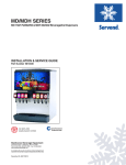
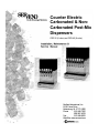
Counter Electric
Carbonated & NonCarbonated Post-Mix
Dispensers
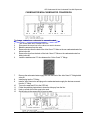
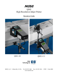
CED-30 (6 valve) and CED-40 (8 valve)
CED Carbonated & Non-Carbonated Post-Mix Dispensers
TABLE OF CONTENTS
Foreword
Warranty Information
Safety Instructions
Daily Checklist for the Operator
OVERVIEW: CED SERIES BEVERAGE DISPENSERS
Counter Electric Unit Description
CED Unit with Internal Cold Carbonator
External Carbonator Unit
Non-Carbonated Unit
EQUIPMENT OVERVIEW
Carbonated Units
Non-Carbonated Units
EQUIPMENT INSTALLATION OVERVIEW
BIB Installation Diagram
Selecting Location
Placing Unit in the Operating Position
Fill Water Tank and Start Refrigeration System
Incoming Water Supply Requirements
Connecting the Drain Pan Hose
Connecting the Water Source Line(s) to the Unit
Connecting the CO2 source Line to the Unit
Connecting the Syrup Source Lines to the Unit
CED - 30 AND CED - 40
Unit with Internal Carbonator
Unit with External Carbonator
Non-Carbonated Unit
Equipment Installation Specifications (CED-30)
Equipment Installation Specifications (CED-40)
SANITIZING AND CLEANING
Daily Cleaning
Periodic Sanitizing of the Beverage System
Bag-in-Box Sanitizing
Figal Sanitizing
CARBONATED/NON-CARBONATED CONVERSION
INSTRUCTIONS
4
4
5
5
6
6
6
6
7
7
8
9
10
10
11
12
12
13
13
13
13
13
14
15
16
18
18
18
20
8
13
18
21
CED Carbonated & Non-Carbonated Post-Mix Dispensers
WIRING DIAGRAMS
23
TROUBLESHOOTING GUIDE
Warm Drinks
No Water, Syrup or Gas Dispensing
Water Only Dispensing
Syrup and CO2 Only Dispensing
Syrup Only Dispensing
Syrup and Plain Water Only Dispensing
One Valve Will Not Dispense Anything
Beverage Dispensed is Too Sweet
Beverage is not Sweet Enough
Drinks are Foaming
25
25
26
26
26
26
26
26
26
26
25
CED Carbonated & Non-Carbonated Post-Mix Dispensers
FOREWORD
SerVend developed this manual as a reference guide for the owner/operator, service agent, and
installer of this equipment. Please read this manual before installation or operation of the machine.
Consult the troubleshooting guide within this manual for service assistance
If you cannot correct the service problem, call your SerVend Service Agent or Distributor. Always
have your model and serial number available when you call.
Your Service Agent ____________________________________________________________
Service Agent Telephone Number _________________________________________________
Model Number _______________________________________________________________
Serial Number _______________________________________________________________
The model and serial numbers are located on the right side of the dispenser, just behind the drainpan.
Installation Date ______________________________________________________________
Your Local SerVend Distributor ___________________________________________________
Distributor Telephone Number____________________________________________________
A qualified service technician should perform installation and start-up of this equipment.
UNPACKING AND INSPECTION
Note: The CED Unit was thoroughly inspected before leaving the factory. Any damage or irregularities
should be noted at the time of delivery (or not later than 15 days from the date of delivery.)
WARRANTY INFORMATION
Consult your local SerVend Distributor for terms and conditions of your warranty. Your warranty
specifically excludes all beverage valve brixing, general adjustments, cleaning, accessories and
related servicing.
Your warranty card must be returned to SerVend to activate the warranty on this equipment. If a
warranty card is not returned, the warranty period can begin when the equipment leaves the SerVend
factory.
No equipment may be returned to SerVend without a written Return Goods Authorization (RGA).
Equipment returned without an RGA will be refused at SerVend's dock and returned to the sender at
the sender's expense.
Please contact your local SerVend distributorfor return procedures.
CED Carbonated & Non-Carbonated Post-Mix Dispensers
SAFETY INSTRUCTIONS
Installation and start-up of this equipment should be done by a qualified service technician.
Operation, maintenance, and cleaning information in this manual are provided for the user/operator
of the equipment.
CED Carbonated & Non-Carbonated Post-Mix Dispensers
IMPORTANT: TO THE USER OF THIS SERVICE MANUAL, THIS MANUAL IS A GUIDE FOR INSTALLING
THIS EQUIPMENT. REFER TO THE TABLE OF CONTENTS FOR PAGE LOCATION FOR DETAILED
INFORMATION PERTAINING TO QUESTIONS THAT ARISE DURING INSTALLATION AND START-UP
OF THIS EQUIPMENT.
OVERVIEW: CED SERIES BEVERAGE DISPENSERS
This section gives the Counter-Electric Unit description, theory of operation, and service data for the
6 and 8 flavor Post Mix Dispensers (hereafter referred to as CED Units.)
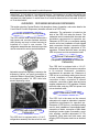
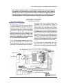
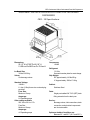
Counter-Electric Description
The CED Units are small compact chillers with a
high-impact and corrosion-resistant stainless
steel housing and may be island mounted or
installed on a front or rear counter. The
refrigeration assemblies are the drop-in-type that
can be removed for service and maintenance.
carbonator. The carbonator is located on the
deck of the CED Unit under the bonnet. The
carbonator tank is located within the water tank.
Installation requirements for operation are:
Placement of CED Unit on a countertop making
sure the unit is level, installation of loose shipped
parts, connection of drains, connection of plain
water and syrup supplies, adjustment of CO2
regulators, fill water tank with water, and plug
CED Unit power cord into an electrical outlet.
External Carbonator Unit
(Requires Connection to a Remote
Carbonator)
Adjustable syrup flow regulators, located on the
dispensing valves, are easily accessible to
control the Water to Syrup Ratio (Termed Brix) of
the dispensed product. All CED Units have
electric dispensing valves.
This CED Unit is equipped with a 1/3 H.P.
refrigeration assembly and requires connection
to an external Carbonator. Installation
requirements for operation are: Placement of
CED Unit on a countertop making sure the unit
is level, installation of loose shipped parts,
connection of drain, connection of external
carbonator, connection of plain water and syrup
supplies, adjustment of CO2 regulators, fill water
tank with water, and plug CED Unit power cord
into an electrical outlet.
Non-Carbonated CED Unit
CED Unit with Internal Cold
Carbonator
This CED Unit is equipped with a 1/3 H.P.
refrigeration assembly and has a built-in cold
This CED Unit is the same as the external
carbonator unit, except no carbonator is required.
Installation requirements for operation are:
Placement of CED Unit on a countertop making
sure it is level, installation of loose shipped parts,
connection of drains, connection of plain water
including a booster system if necessary, syrup/
juice supplies, possible adjustment of CO2
regulators, filling water tank with water, and
plugging CED Unit power cord into an electrical
outlet.
CED Carbonated & Non-Carbonated Post-Mix Dispensers
Note: Before shipping, storing, or relocating this CED Unit, the syrup systems must
be sanitized and all sanitizing solution must be purged from the syrup systems.
All water must also be purged from the plain and carbonated water systems. A
freezing ambient environment will cause residual water in the CED Unit to freeze
causing expansion of tubing and resulting in damage to internal components.
EQUIPMENT OVERVIEW
Carbonated Units
Internal Cold Carbonator
The CED 30 is a 6 valve unit set up to dispense
a noncarbonated drink from the NO. 3
dispensing valve. The CED 40 is an 8 valve
unit set up to dispense a noncarbonated drink
from the No. 4 and 5 valves. The remaining
dispensing valves on each unit are set to
dispense carbonated beverages. Refer to the
instructions on page 21-22 to convert a
valve from carbonated to non-carbonated
or non-carbonated to carbonated.
A CO2 cylinder delivers carbon dioxide (C02)
gas through adjustable CO2 regulator to the
syrup BIB pump and also to an internal
carbonator. Plain water also enters the internal
carbonator tank, and is carbonated by the
regulated CO 2 gas pressure. When a
dispensing valve is opened, CO 2 pressure
exerted within the syrup BIB pump propels
syrup from the BIB, through the CED Unit
beverage coils, and into the dispensing valve.
Carbonated water is forced from the carbonator
tank by CO 2 pressure which pushes cold
carbonated water into the dispensing valve
resulting in a carbonated drink being dispensed.
A noncarbonated drink is dispensed in the same
manner as a carbonated drink with the exception
that plain water is substituted for carbonated.
The carbonator is replenished when the
carbonated water level inside the tank drops,
which in turn automatically starts the carbonator
CED Carbonated & Non-Carbonated Post-Mix Dispensers
water pump. When the water level inside the tank
has been replenished, carbonator water pump
will stop.
External Carbonator
The CED 30 is a 6 valve unit set up to dispense
a noncarbonated drink from the No. 3 dispensing
valve. The CED 40 is an 8 valve unit set up to
dispense a noncarbonated drink from the No. 4
and 5 valves. The remaining dispensing valves
on each unit are set to dispense carbonated
beverages. Refer to the instructions on page
21-22 to convert a valve from a carbonated
to non-carbonated or from non-carbonated
to carbonated.
A CO2 cylinder delivers carbon dioxide (CO2) gas
through adjustable CO2 regulators to the syrup
BIB pump and also to an external carbonator.
Plain water also enters the remote carbonator
tank, and is carbonated by the regulated CO2 gas
pressure. When a dispensing valve is opened,
CO2 pressure exerted within the syrup BIB pump
propels syrup from the BIB, through the CED Unit
beverage coils, and into the dispensing valve.
Carbonated water is forced from the carbonator
tank by CO2 pressure which pushes carbonated
water through the CED Unit cooling coils, and
into the dispensing valve. Syrup and
carbonated water meet simultaneously and mix
at the nozzle of the dispensing valve resulting in
a carbonated drink being dispensed. A
noncarbonated drink is dispensed in the same
manner as a carbonated drink with the
exception that plain water is substituted for
carbonated.
The Carbonator is replenished when the
carbonated water level inside the tank drops,
which in turn automatically starts the carbonator
water pump. When the water level inside the
tank has been replenished, carbonator water
pump will stop.
Non-Carbonated Units
A CO2 cylinder delivers carbon dioxide (CO2)
gas through adjustable CO2 regulators to the
syrup/juice BIB pump. When a dispensing
valve is activated, pressure exerted upon the
syrup BIB pump propels syrup/concentrate
from the BIB, through the cooling coils, and
into the dispensing valve. Plain water enters
the CED Unit and passes through the cooling
coils to the dispensing valve. Syrup/concentrate
and plain water meet simultaneously in the
dispensing valve and mix at the nozzle resulting
in a still (noncarbonated) drink being
dispensed. For noncarbonated BIB syrup(s)/
concentrate(s) to be delivered at ambient
temperature, refer to the conversion instructions
for bypassing the cooling coil.
Equipment Installation Overview
This section covers unpacking, inspecting, selecting location, installing the Unit, and preparing
for operation.
1. After the unit has been unpacked, remove the
keys. The key will be needed to perform
brixing of valves. Hold onto the keys until such
time to forward them to the respective owner/
operator. Remove tape (which secures grid
in place in drain pan) from grid and other
packing material.
2. Make sure all items are present and in good
condition. Loose shipped items in the carton
include the drain kit parts, S/S "U" tube, John
Guest fitting and the instructions.
3. Inspect CED Unit for any external damages.
CED Carbonated & Non-Carbonated Post-Mix Dispensers
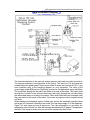
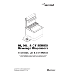
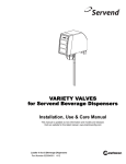
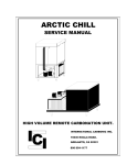
BIB Installation Diagram
The internal carbonator in the post-mix system has two inlets and one outlet connection.
The internal carbonator is pre-plumbed at the factory. The inlets for CO2 and water are
located behind the splash panel. There are two inlets for water and one inlet for CO2. If you
have questions refer to the plumbing diagram on your equipment. The outlet of the
syrup supply (either BIB pump or Figal tank) connects to the appropriate syrup inlet fitting.
The syrup flows through the ice bath to be chilled on its way to the valves. The water flows
through the ice bath to the internal carbonator then back through the ice bath chilling
the carbonated water on its way to the valves. When both fluids leave the beverage valve
they are mixed in the nozzle of the valve. Out comes a properly cooled, properly ratioed
soft drink.
When starting a new beverage system of either type, be sure the electrically operated valves
are turned off. Assure all connections are made, turn the water supply on to the dispenser.
Open CO2 tank valve and set all pressures. Turn the refrigeration on and allow the
refrigeration coils to fill with ice. After the beverage has achieved a 40 degree F temperature,
the ratio of the syrup-to-water (brix) on a post-mix system may then be set.
CED Carbonated & Non-Carbonated Post-Mix Dispensers
Selecting Locations
The CED Unit may be island-mounted or
installed on a front or rear counter. Locate the
CED Unit so the following requirements are
satisfied: Unit is for indoor use only.
1. Unit must be installed near a properly
grounded electrical outlet with proper
electrical requirements fused at 20 amps
("slow-blow") or circuit connected through an
equivalent HACR circuit breaker with ELCB
(GFCI). REFER TO UNIT NAMEPLATE
FOR THE REQUIRED POWER CIRCUIT
OPERATING VOLTAGE. Hz AND THE
MINIMUM CIRCUIT AMPACITY OF THE
UNIT. No other electrical equipment should
be connected to this circuit.
ALL
ELECTRICAL WIRING MUST CONFORM
TO NATIONAL AND LOCAL ELECTRICAL
CODES.
MAIN PLUG MUST BE
ACCESSIBLE FOR DISCONNECTION. The
key switch is able to be mounted on either
side of the CED Unit. When the location for
the CED Unit is selected, make sure the key
switch is mounted where it will be most
accessible.
2. A minimum of 15-inches clearance must be
maintained above the CED Unit to the nearest
obstruction (shelf, cupboard, ceiling, etc.)
and 4-inches clearance between back-side
of the Unit and the wall and 12" each side of
wall. Unit has top air outlet and is to remain
free of all objects. Do not place anything
on top of the CED Unit. The rear grill of the
CED Unit must be unobstructed to allow air
to enter the hood.
3. Place CED Unit close to a permanent drain
in order to route the drain pan hose to the
permanent drain. Water tank overflow hose
goes into the drain pan.
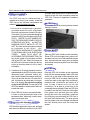
Placing Unit in the Operating Position
CED Unit inlet supply lines, power cord, and drain
pan hose must either be routed out of the CED
Unit base back access hole, or if island-mounted,
through a hole cut in the countertop under the
CED Unit. Proceed to applicable installation
procedure.
All CED Units
Remove the Bonnet by removing the two screws
holding it in place.
Counter Mount
Place the CED Unit in location on the countertop.
Route CED Unit inlet supply lines, power cord,
and drain pan hose out of the base back access
hole. Area around inlet supply lines at flanged
hole behind front access panel must be closed
and sealed.
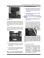
Island Mount
Place the CED Unit in location on the countertop
flush with the countertop edge. Mark CED Units
center line on the edge of the countertop, then
move the CED Unit to one side. Starting at the
center line mark on the edge of the countertop,
measure back 12-inches for the location of a
hole at least 4 inches to be cut into the
countertop. Cut at least a 4 inch hole in the
countertop where indicated. Place the CED Unit
in position over the hole. Route the inlet supply
lines, power cord, and drain pan hose down
through the hole in the countertop. Install the
line outlet plug, provided with the CED Unit in
the base back access hole. The area around
the inlet supply lines at the flanged hole behind
the front access panel must be closed and
sealed.
CED Carbonated & Non-Carbonated Post-Mix Dispensers
the countertop will be broken.
D. Apply additional sealant around the bottom
of the base. The seal must be a minimum of
1/4 inch to prevent crevices and to ensure a
complete seal.
E. Close and seal all access holes to the inside
of the CED Unit base.
Fill Water Tank and Start Refrigeration
System
All CED Units
To comply with National Sanitation Foundation
(NSF) requirements within the United States, the
CED Unit base must be sealed to the countertop
unless the optional 4" legs are installed (see
above).
All access holes to the base must be sealed. If
the 4" legs are installed, proceed to step E,
otherwise proceed as follows to seal the CED
Unit base.
A. Tilt CED Unit up to expose bottom of base.
B. Liberally apply silastic sealant such as Dow
Corning RTV 731 or equivalent on the base
bottom edges.
C. Lower the CED Unit into operating position
on the counter top to complete the seal of
the base to the countertop.
Note:
Do not move CED Unit after
positioning or the seal between the base and
1. Make sure the plug in the water tank drain
hose is secure.
2. Remove the plug from the water fill hole
located on the carbonator pump deck. Fill
the water tank with clean water until water
flows out of the tank overflow. Use a funnel if
necessary. Caution: Be careful not to
spill water on any electrical fitting or
connection. Do not use distilled water.
Note: An alternative method to fill the water
tank would be to temporarily splice the
incoming water line into the water tank drain
hose, turn on the water and fill the tank until
water comes out the overflow drain. Turn
off the water and plug the water tank drain
hose.
3. Install plug in waterfill hole.
4. Place CED Unit refrigeration system switch
and the agitation switch, located on the side
of the control box, in "OFF" position ON A
UNIT WITH AN INTERNAL COLD
CARBONATOR, DISCONNECT THE
POWER SUPPLY TO THE CARBONATOR
AT THIS POINT. OTHERWISE WATER
PUMP DAMAGE WILL OCCUR.
Incoming Water Supply Requirements
NOTE: SerVend International Inc.
recommends that a water shutoff valve and
water filter be installed in the incoming water
supply line. A SerVend Water Filter and
Quick Disconnect Set are recommended.
WARNING: CED Unit must be electrically
grounded to avoid possible fatal electrical shock
or serious injury to the operator. Unit power cord
is equipped with a three-prong. If a three-hole
(grounded) electrical outlet is not available, use
an approved method to ground the CED Unit.
Refrigeration System Start
A. Plug CED Unit power cord into an accessible
properly grounded electrical outlet with
GFCI.
The incoming water source to the equipment shall
be installed with adequate backflow protection
to comply with applicable Federal, State, and
local codes.
Water pressure should be a minimum of 45 PSI
or you will starve the pump of water and damage
it. The maximum water pressure should be 55
psi or you will affect the quality of the carbonation.
The carbonator pump should be located within
6 feet of a 112 inch water source. A minimum 3/
8 inch ID water line must be used. Before
connection the water source should be flushed
of approximately 5 gallons of water to purge the
system of any sediments, especially in areas of
new construction.
B. Place CED Unit refrigeration system switch
and agitation switch located on the side of
the control box, in "ON" position.
Compressor, condenser fan motor, and
agitator motor will start and begin forming
an ice bank. When a full ice bank has been
formed, the compressor and condenser fan
motor will stop, but the agitator motor will
continue to operate, circulating ice bath
water in the water tank. Turn the key switch
to the "ON" position to check all beverage
valves for operation. Check for water, syrup,
and CO 2 leaks in the supply system.
Replace the bonnet with the two screws
provided.
Recommended:
Beverage
pour
temperature should be maintained at a
constant 40° F or below for optimum
brixing value. Time required to reach the
proper temperature will be subject to
water and ambient air temperatures.
Connecting the Drain Pan Hose
NOTE: Connection of the drain pan hose to
a permanent drain is recommended. A drain
pan hose routed to a waste container is not
recommended due to sanitation problems.
1. Connect drain pan hose to the nipple on the
drain pan.
2. Install drain pan in position on the CED Unit,
then place grid in the drain pan.
3. Route lower end of drain pan hose to a
permanent drain and connect.
CED Carbonated & Non-Carbonated Post-Mix Dispensers
Connecting Water Source Line(s)
to the CED Unit
Internal Carbonator
Connect plain water source line to the CED Unit
at the plain water inlet line, and the noncarbonated water inlet.
External Carbonator
Connect carbonated water source line from the
external carbonator to the CED Unit at the
carbonated water inlet line.
Connect plain water source line to the CED Unit
at the non-carbonated water inlet line.
Noncarbonated Unit
Connect plain water source lines to the CED Unit
at the plain water inlet line and the noncarbonated water inlet.
Connecting CO2 Source Line to the Unit
Internal Carbonator
Connect the CO2 source line to the CED Unit at
the CO2 inlet line.
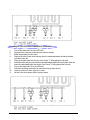
Connecting Syrup Source Lines
to All CED Units
Connect syrup source lines to the CED Unit at
the corresponding syrup inlet lines. Syrup inlet
line #1 will correspond with the right hand
dispensing valve. The valves are numbered in
sequence from right to left.
CED Unit with Internal Carbonator
1. Connect CO2 supply to the CO2 inlet at the
CED Unit.
2. Open pressure relief valve. (Red arm should
be in the upright position).
3. Turn water supply on and fill the carbonator
tank until water can be seen coming out the
pressure relief valve.
4. Close the pressure relief valve.
5. Activate a dispensing valve until a good flow
of plain water is established.
6. Check for water leaks.
7. Turn on the CO2 bottle and adjust the regulator
to 75 psi.
8. Activate a valve until all the water has been
forced out of the system by the CO2.
9. Check for any leaks.
10. Connect the power to the carbonator.
11. Operate the valves until the carbonator cycles
several times and there is a good flow of
carbonated water from each valve.
CED Unit with External Carbonator
1. Connect CO2 supply to the CO2 inlet on the
carbonator tank.
2. Connect carbonated water outlet line to the
dispensing system. To avoid contamination
of potable liquids, do not connect copper
tubing or fittings between the discharge
fitting on the carbonator and the dispensing
valve.
3. Open pressure relief valve. (Red arm should
be in the upright position).
CED Carbonated & Non-Carbonated Post-Mix Dispensers
4. Turn water supply on and fill the carbonator
tank until water can be seen coming out the
pressure relief valve.
10.Check for any leaks.
5. Close the pressure relief valve.
12. Operate the valves until the carbonator cycles
several times.
6. Activate a dispensing valve until a good flow
of plain water is established.
7. Check for water leaks.
8. Turn on the CO 2 bottle and adjust the
regulator to 100 psi.
9. Activate a valve unti I al I the water has been
forced out of the system by the CO2.
11. Plug in the carbonator.
Non-Carbonated Unit
1. Open plain water inlet supply line shutoff
valve. Check for water leaks and tighten any
loose connections.
2. Operate each dispensing valve until the
system is flushed and water flows smoothly
from each valve.
CED Carbonated & Non-Carbonated Post-Mix Dispensers
EQUIPMENT INSTALLATION SPECIFICATIONS FOR CED SERIES
DISPENSERS
CED - 30 Specifications
Dimensions:
20 11T W x 27 3/8" D x 28 1 /4" H
51.435 cm W x 69.53 cm D x 72.4 cm H
Ice Bank Size:
30 lbs/13.636 kg
Valves:
Six beverage valves
Standard Voltage:
120/60/1
6 - foot (1.82m) three-wire cord and plug
provided.
Fuse Size:
Minimum 15 amp
Amperage:
8.2 Operating amps
Other voltage available:
220 Volts-50 Hz-1 Ph
Fuse Size:
Minimum 10 amp
Amperage:
4.5 Operating amps
Compressor:
1/3 HP
Refrigerant:
R-134a
See serial number plate for exact charge.
Ship Weight:
EC Approximately 143 lbs/65 kg.
IC Approximately 158 lbs/71.8 kg
Cabinet:
Stainless Steel
Drain:
Single pre-installed 3/4" PVC (NPT) drain
fitting extends from the drain pan.
Service:
Beverage valves, inlet connections, drain
connection, and electrical components
are front accessible.
Optimum Ambient Conditions are:
Between 50 ° and 95°F (10°C and 35°C).
CED Carbonated & Non-Carbonated Post-Mix Dispensers
EQUIPMENT INSTALLATION SPECIFICATIONS FOR CED SERIES
DISPENSERS
CED - 40 Specifications
Dimensions:
25 114" W x 27 3/8" D x 28 114" H
63.1 cm Wx 69.53 cm D x 72.4 cm H
Ice Bank Size:
Up to 40 lbs/18.182 kg
Valves:
Eight beverage valves
Standard Voltage:
120/60/1
6 -foot (1.82m) three-wire cord and plug
provided.
Fuse Size:
Minimum 15 amp
Amperage:
8.2 Operating amps
Other voltage available:
220 Volts-50 Hz-1 Ph
Fuse Size:
Minimum 10 amp
Amperage:
4.5 Operating amps
Compressor:
1/3 HP
Refrigerant:
R-134a
See serial number plate for exact charge.
Ship Weight:
EC Approximately 160 lbs/72.7 kg.
IC Approximately 175 lbs/79.5 kg
Cabinet:
Stainless Steel
Drain:
Single pre-installed 3/4" PVC (NPT) drain
fitting extends from the drain pan.
Service:
Beverage valves, inlet connections, drain
connection, and electrical components
are front accessible.
Optimum Ambient Conditions are:
Between 50 ° and 95°F (10°C and 35°C).
CED Carbonated & Non-Carbonated Post-Mix Dispensers
OPERATION All CED
Units Bag-in-Box (BIB)
Start-up
All lines should be properly flushed and
sanitized before starting the CED Unit.
Sanitizing instructions can be found
beginning on page 18 of the Installation
Manual.
1. Connect each BIB connector to the
appropriate BIB.
2. Gradually adjust the secondary regulator to
45 psi. Never run a BIB pump without the
BIB ins tal led as the pump c ould be
damaged. Set final secondary regulator
pressure per pump manufacturer's
guidelines for line size and the distance of
the run.
3. Operate each dispensing valve until the
syrup flows smoothly from the valve.
Adjust Syrup to Water Ratio (Brix) of
Dispensed Product.
1. Adjust water flow rate on each dispensing
valve to 2.5 ounces per second.
2. Adjust dispensing valves for water-to-syrup
ratio (brix) as recommended by the syrup
distributor.
Install Decals
Install decals (provided with CED Unit) on
dispensing valve covers.
Clean Up
Clean up all work areas. Dispose of all packing
material, excess tubing and trash properly.
4. Wash the grid, then rinse with clean water.
Place the grid back in the drain pan.
5. Wash al I exterior surfaces of the unit with warm
water and a clean cloth. Wipe again with a
clean, dry cloth.
6. Remove the nozzles and diffusers from the
dispensing valves.
7. CI ean both the nozzl es and the d iff users wi th
soap and water to remove syrup residue, then
rinse with warm, clean water.
8. Replace the diffusers and the nozzles on
the valves.
Periodic Sanitizing of the Dispenser
SANITIZING AND CLEANING
Note: Scheduled cleaning must be in
compliance with local health codes. This
cleaning schedule is a recommendation.
Daily Cleaning
♦
♦
♦
♦
♦
Drain pan
Grid
Splash Panel
Valve Nozzles
D iff users
You will need: Warm clean water, a mild
nonabrasive soap, and a clean cloth.
1. Lift the grid and remove it from the drain pan.
2. Using warm water, mild soap, and a clean
cloth, wash the drain pan and splash panel.
After cleaning, rinse with clean, warm water.
3. Allow plenty of warm (not hot) tap water to
run down the drain of the drain pan to
remove any syrup residue that can clog the
drain opening.
Note: Sanitize the dispenser at initial startup in addition to periodic sanitizing.
Bag-in-Box
Beverage System Sanitizing
(for trained personnel only)
You will need: Three clean, empty five-gallon
buckets to be used for the rinse, detergent, and
sanitizing buckets, and a container to be placed
under soda valves to carry away detergent and
sanitizing agents which will be flushed through
the valves.
1. Disconnect the bag-in-box connectors.
2. Prepare the following in three clean buckets:
A. Rinse bucket - fill bucket with clean tap
water. (Refill as necessary.)
B. Detergent bucket - mix approved
beverage system cleaner with warm
water as recommended.
C. Sanitizing bucket - mix a solution of 1
ounce of liquid, unscented household
bleach (5.25% Cl Na 0 concentration) with
two gallons of tap water. The mixture
should supply 200 PPM of available
CED Carbonated & Non-Carbonated Post-Mix Dispensers
chlorine.
3. Remove the cap located opposite the tubing
connection on the bag-in-box connector.
4. Place bag-in-box connector in rinse bucket
(step 2A). Draw clean tap water through the
system and out the beverage valve until all
syrup is flushed from the system.
5. Place bag-in-box-connector in the detergent
bucket (step 2B). Draw detergent solution
through the system and out the beverage
valve for 2 minutes. Then, allow the remaining
detergent to stay in the system for 5 minutes.
6. Remove the valve nozzle and diffuser, as
described in the daily cleaning instructions.
Using a clean cloth or a soft brush, scrub the
nozzle, the diffuser, the bottom of the
dispensing valve, and the cup lever, if
applicable.
7. Place the valve diffuser and nozzle in
sanitizing solution for 20 minutes, then
replace them on the beverage valve.
8. Place bag-in-box connector in the sanitizing
bucket (step 2C). Draw sanitizing solution
through the system and out the valve for 5
minutes. Allow the sanitizing solution to
remain in the system for a minimum of 20
minutes.
9. Place the bag-in-box connector in the rinse
bucket (step 2A). Draw clean rinse water
through the system and out the valve for 2
minutes, flushing the sanitizing solution from
the system.
10.Repeat Step 8 and Step 9.
11. Replace the plastic cap opposite the tubing
connection on the bag-in-box connector.
12.Reconnect the bag-in-box connector to the
beverage syrup bag-in-box.
13.Repeat the above steps for each beverage
valve, or follow this procedure with any
number of valves concurrently.
CED Carbonated & Non-Carbonated Post-Mix Dispensers
Figal Beverage System Sanitizing
1. Prepare the following in three clean Figal
tanks:
a) Rinse tank - fill with room temperature
water.
b) Detergent tank - mix approved beverage
system cleaner with warm water as
directed.
c) Sanitizing tank - mix a solution of 1
ounce of unscented household bleach
(5.25% Cl Na 0 concentration) to two
gallons of tap water. The mixture should
supply 200 PPM available chlorine.
2. Locate the Figal syrup tank for the circuit to
be sanitized.
Remove both quick
disconnects from the Figal syrup tank. Rinse
quick disconnects in warm tap water.
3. Connect rinse tank to the syrup line. Draw
clean rinse water through the valve until
syrup is flushed from the system.
4. Connect detergent tank to the syrup line and
draw detergent through the valve for 2
minutes. Then, allow remaining detergent
to stay in the system for 5 minutes.
5. Follow steps 6 and 7 in the bag-in-box
sanitizing instructions to clean and sanitize
the beverage valve nozzle and diffuser.
6. Connect sanitizing tank to the syrup line and
draw sanitizing solutions through the valve
for 5 minutes. Allow sanitizing solution to
remain in the system for a minimum of 20
minutes.
7. Connect rinse tank to the syrup line. Draw
clean rinse water through the system for two
minutes to flush the sanitizing solution from
the system.
8. Repeat Step 6 and Step 7.
9. Reconnect syrup lines.
CED Carbonated & Non-Carbonated Post-Mix Dispensers
CARBONATED/NON-CARBONATED CONVERSION
To change a valve from carbonated to non-carbonated:
1.
Turn off the water and CO2tothe CED Unit.
2.
Disconnect the syrup box to the valve you want to change.
3.
Bleed the pressure from the valve.
4.
Remove the plug from the back of the John Guest "Y" fitting on the non-carbonated water line
behind valve #4.
5.
Remove the plug from the back of the John Guest "Y" fitting on the carbonated water line
behind valve #3.
6.
Install the stainless steel "U" tube between the 2 John Guest "Y1 fittings.
7.
8.
9.
10.
11.
12.
13.
Remove the carbonated water supply line from the back of the John Guest "Y" fitting behind
valve #3.
Install a plug into the "Y" fitting.
Install a John Guest union and plug on the carbonated water supply line that was removed
from the "Y" fitting.
Turn on the water and CO2 to the CED Unit.
Follow the sanitizing instructions to clean the old syrup from the line.
Hook up a fresh box of the syrup to be used.
Set the valve to the proper ratio of syrup to water.
CED Carbonated & Non-Carbonated Post-Mix Dispensers
To change a valve from non-carbonated to carbonated:
1.
2.
3.
4.
5.
6.
7.
8.
9.
10.
11.
Turn off the water and CO2 to the CED Unit.
Disconnect the syrup box to the valve you want to change.
Bleed the pressure from the valve.
Remove the John Guest union and plug from the carbonated water line that is stubbed
out behind valve #4.
Remove the plain water line from the John Guest "Y" fitting going into valve #4.
Install the union and plug removed from the carbonated water line into the plain water line.
Insert the carbonated water line into the John Guest "Y" fitting behind the #4 valve.
Turn on the water and CO2 to the CED Unit.
Follow the sanitizing instructions to clean the old syrup from the line.
Hook up a fresh box of the syrup to be used.
Set the valve to the proper ratio of syrup to water.
CED Carbonated & Non-Carbonated Post-Mix Dispensers
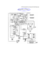
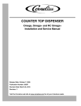
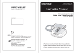
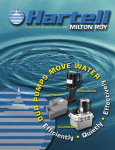
Wiring Diagram 115 volt/60/1
CED Carbonated & Non-Carbonated Post-Mix Dispensers
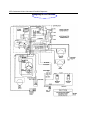
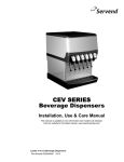
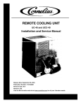
Wiring Diagram 220 volt/50 Hz
CED Carbonated & Non-Carbonated Post-Mix Dispensers
TROUBLESHOOTING GUIDE
CONDITION
Warm drinks
INVESTIGATION
Is the compressor running?
CHECK
Power switch off.
No.
CORRECTION
Move switch to "on"
position
Ice bank control
Check/replace control
Compressor overload
Check/replace overload
Start relay
Check/replace relay
Compressor
Check/replace
compressor
Note A: It is important to remember that anytime the refrigeration system is opened the refrigerant
should be recovered, a new drier installed and the proper charge of refrigerant weighed into the
refrigeration system.
Is the compressor running?
Condenser dirty
Clean air filter
Yes.
Condenser blocked
Remove obstruction
Fan not running
Replace fan motor
No Agitation
Check/replace impeller
Check/replace agitation
motor
Refrigerant level low
Repair leak, charge with
refrigerant. See note A
above.
No water, syrup or gas
Is there power to the unit?
No power
Is power coming through key
Key switch "off'
Turn key switch "on"
switch?
Is there power to the key
switch?
Is unit frozen?
Key switch defective
No power through the
transformer
Water level low
Replace key switch
Ice bank control
Check/replace control.
dispensing.
Plug in unit or reset
breaker
Reset/replace transformer
Check/refill ice bath
See Note B below.
Note B: In order to check the ice bank control you must check the resistance between probes 5 and 7
and between 6 & 7. The refrigeration unit will start when a resistance less than 45K ohms is detected
across probes 5 & 7. The refrigeration unit will stop when the ice bank covers all the probes, which will
create a resistance greater than 85K ohms between probes 6 & 7. If the probe registers the proper
resistance and the CED won't refrigerate or freezes solid, replace the control module. If the probe does
not register the proper resistance, replace the probe and the ice bank control module. The ice bank
control module is mounted in the control box on the refrigeration deck. It may be replaced without
removing the probe from the water bath. The ice bank control probe may be accessed by removing the
carbonator deck. The probe can be thawed and removed without removing the refrigeration deck from
the CED Unit.
CED Carbonated & Non-Carbonated Post-Mix Dispensers
CONDITION
Water only dispensing
Syrup and CO2 only
dispensing
INVESTIGATION
No pressure
Carbonator
CHECK
CORRECTION
Regulators) out of
adjustment
Check/adjust regulator(s)
OutofC0 2
Install fresh tank
Defective regulator(s)
Check/repair/replace regulators)
CO2 line pinched, kinked or
obstructed
Check/repair/replace CO2 line
No power
Check power supply. Plug in carbonator
or reset breaker.
Water supply
Make sure water is turned "on"
Replace water filter
Check/clean/replace pump strainer
Check/clean/repair water check valve
Check for frozen water line. Internal
Carbonator unit only.
Defective carbonator
Check/repair/replace carbonator pump,
motor, electrode or liquid level control.
Syrup only dispensing
Is sodaA/vater
line frozen?
Defective ice bank control
Replace ice bank control. See note B.
Syrup and plain water
No pressure
OutofCCX,
Install fresh tank
HP regulator out of
adjustment
Adjust HP regulator to the proper setting
Defective HP regulator
Check/repair/replace HP regulator
CO2 line pinched, kinked or
obstructed
Broken wire or loose
connection
Check/repair/replaceCO2 line
Bad microswitch
Replace microswitch
Is the ratio (brix)
of the drink
Flow control out of
adjustment
Adjust the flow control
correct?
Insufficient soda flow due to
Adjust CO2 pressure or change the tank
only dispensing
One valve will not
dispense anything
Beverage dispensed
is too sweet
Is there power
to the valve?
Replace/repair wire or connector
low carbonator pressure
Beverage is not sweet
enough
Drinks are foaming
Low CO2 pressure due to
leaks
Obstruction in the water or
soda line
Repair CO2 leaks
Is the ratio (brix)
of the drink
Flow control out of
adjustment
Adjust the flow control
correct?
Soda flow too high due to
high pressure
Reset CO2 pressure or replace regulator
if necessary
Obstruction in syrup line
Clean out the syrup line
Are system
pressures
Over carbonation
Check CO2 supply. Reset pressure or
replace regulator if necessary
correct?
Dirty lines/valves
Clean/sanitize entire system
Clean out the lines