1
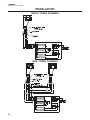
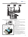
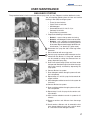
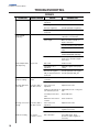
BLADE TOWER 2 Valve Root Beer Dispenser INSTALLATION & SERVICE GUIDE Part Number 020001448 Notice: DO NOT throw this manual away. This manual contains important information regarding this product. Keep this manual at the dispenser location. Manitowoc Beverage Equipment 2100 Future Drive Sellersburg, IN 47172-1868 Tel: 812.246.7000, 800.367.4233 Fax: 812.246.9922 www.manitowocbeverage.com In accordance with our policy of continuous product development and improvement, this information is subject to change at any time without notice. April 01, 2008 REV0 FOREWORD Manitowoc Beverage Equipment (MBE) developed this manual as a reference guide for the owner/ operator, service agent, and installer of this equipment. Please read this manual before installation or operation of the machine. A qualified service technician should perform installation and startup of this equipment, consult the Troubleshooting Guide within this manual for service assistance. If you cannot correct the service problem, call your MBE Service Agent or Distributor. Always have your model and serial number available when you call. Your Service Agent ___________________________________________________________________ Service Agent Telephone Number ______________________________________________________ Your Local MBE Distributor ___________________________________________________________ Distributor Telephone Number _________________________________________________________ Model Number ______________________________________________________________________ Serial Number _______________________________________________________________________ Installation Date _____________________________________________________________________ UNPACKING AND INSPECTION Note: The unit was thoroughly inspected before leaving the factory. Any damage or irregularities should be noted at the time of delivery. WARRANTY INFORMATION Consult your local MBE Distributor for terms and conditions of your warranty. Your warranty specifically excludes all beverage valve brixing, general adjustments, cleaning, accessories and related servicing. Your warranty card must be returned to Manitowoc Beverage Equipment to activate the warranty on this equipment. If a warranty card is not returned, the warranty period can begin when the equipment leaves the MBE factory. No equipment may be returned to Manitowoc Beverage Equipment without a written Return Merchandise Authorization (RMA). Equipment returned without an RMA will be refused at MBE’s dock and returned to the sender at the sender’s expense. Please contact your local MBE distributor for return procedures. TABLE OF CONTENTS FOREWORD ........................................................................................................ 2 UNPACKING AND INSPECTION ......................................................................... 2 WARRANTY INFORMATION ............................................................................... 2 SAFETY ............................................................................................................... 5 IMPORTANT SAFETY INSTRUCTIONS ........................................................................... 5 CARBON DIOXIDE WARNING ......................................................................................... 5 QUALIFIED SERVICE PERSONNEL ................................................................................ 5 SHIPPING, STORAGE, AND RELOCATION ..................................................................... 5 ADDITIONAL WARNINGS ................................................................................................ 5 INSTALLATION .................................................................................................... 6 UNIT INSPECTION ........................................................................................................... 6 PRE-INSTALLATION CHECK LIST .................................................................................. 6 STARTING YOUR BEVERAGE SYSTEM AND DISPENSER ............................................ 6 SPECIFICATIONS ............................................................................................................ 6 BLADE TOWER DIMENSIONS ........................................................................................ 7 COUNTER TOP FOOTPRINT ........................................................................................... 7 UNIT INSTALLATION ....................................................................................................... 8 BASIC B-I-B SYSTEM & PRESSURES ............................................................................ 8 DRAINAGE OPTIONS ...................................................................................................... 9 PLUMBING DIAGRAM LOCATION .................................................................................. 9 SINGLE TOWER PLUMBING ......................................................................................... 10 DUAL TOWER PLUMBING ............................................................................................ 10 TRIPLE TOWER PLUMBING .......................................................................................... 11 BRIXING PROCEDURE ................................................................................................... 11 SYRUP DELIVERY SYSTEM .......................................................................................... 12 BACK ROOM PACKAGE ............................................................................................... 12 RACKING ....................................................................................................................... 13 B-I-B ............................................................................................................................... 13 PUMPS ........................................................................................................................... 13 AUTO BAG SELECTORS ............................................................................................... 13 TABLE OF CONTENTS USER MAINTENANCE ...................................................................................... 13 PREVENTATIVE MAINTENANCE .................................................................................. 13 WINTERIZATION ............................................................................................................ 13 CO2 HANDLING ............................................................................................................. 13 HOW TO DISASSEMBLE TOWER COMPONENTS ....................................................... 14 CLEANING EQUIPMENT AND SUPPLIES ..................................................................... 14 CLEANING & SANITIZING THE DISPENSING VALVES & PRODUCT LINES ............... 14 MAINTENANCE SCHEDULE ......................................................................................... 15 NIGHTLY SHUTDOWN PROCEDURE ............................................................................ 15 CLEANING AND SANITIZING PROCEDURE ................................................................. 16 BEVERAGE SYSTEM CLEANING ................................................................................. 16 BAG-IN-BOX SYSTEM ................................................................................................... 17 TROUBLESHOOTING ....................................................................................... 18 DRINKS .......................................................................................................................... 18 Installation and Service Manual SAFETY IMPORTANT SAFETY INSTRUCTIONS Carefully read all safety messages in this manual. Learn how to operate the A&W Tower unit properly. Do not allow anyone to operate the unit without proper training and keep it in proper working condition. Unauthorized modifications to the A&W Tower may impair function and/or safety and affect the life of the unit. CARBON DIOXIDE WARNING DANGER: Carbon Dioxide (CO2) displaces oxygen. Exposure to a high concentration of CO2 gas causes tremors, which are followed rapidly by loss of consciousness and suffocation. If a CO2 gas leak is suspected, particularly in a small area, immediately ventilate the area before repairing the leak. CO2 lines and pumps should not be installed in an enclosed space. An enclosed space can be a cooler or small room or closet. This may include convenience stores with glass door self serve coolers. If you suspect CO2 may build up in an area, venting of the B-I-B pumps and / or CO2 monitors should be utilized. QUALIFIED SERVICE PERSONNEL WARNING: Only trained and certified electrical and plumbing technicians should service this unit. All wiring and plumbing must conform to national and local codes. SHIPPING, STORAGE, AND RELOCATION CAUTION: Before shipping, storing, or relocating this unit, syrup systems must be sanitized. After sanitizing, all liquids (sanitizing solution and water) must be purged from the unit. A freezing environment causes residual sanitizing solution or water remaining inside the unit to freeze, resulting in damage to internal components. ADDITIONAL WARNINGS Installation and start-up of this equipment should be done by a qualified service technician. Operation, maintenance, and cleaning information in this manual are provided for the user/operator of the equipment. Save these instructions. 5 INSTALLATION UNIT INSPECTION Installation and Service Manual Included with each Blade Tower should be one (1) installation kit (020001441) and if multiple towers are being installed a tee kit (020001411) is included with each additional tower. Listed below are the contents of each kit; 020001441- KIT INSTL 2 VLV RB BLADE TOWER Item Description Quantity 00861302 020001403 11.3-505R 15514500 18.5-706R 020001448 0901803 020002097 00850812 5006594 SPLICER 1/4 X 3/8 BARB SS UBEND BARB 1/2 X 1/2 X 28 1/4 CLAMP STEPLESS SS CLAMP STEPLESS SS 14.5MM CLAMP STEPLESS SS MAN A AND W BLADE TOWER WASHER FLAT #10 ZINC SCR 10-24 X 2 SS NUT HEX 10-24 SS WASHER STAR #10 SS 2 1 4 2 2 1 4 4 4 4 020001411- KIT CONDUIT TEE 4 LINE Item Description Quantity 00854996 5009851 15514500 18.5-706R 1900315 5029545 ELL 1/2 X 1/2 BARB SS TEE 3/8 BARB CLAMP STEPLESS SS 14.5MM CLAMP STEPLESS SS BAG 9X12 CLR ZIPLOCK TAPE 3IN X 60FT BLK 2 2 6 4 1 1 Thoroughly inspect the unit upon delivery. Immediately report any damage that occurred during transportation to the delivery carrier. Request a written inspection report from a claims inspector to document any necessary claim. PRE-INSTALLATION CHECK LIST When installing any system, first make sure the major components are available. Generally the major components necessary for an installation are: Pre-mix system: B-I-B System: CO2 regulator set Product connectors for tank Gas connectors for tank Beverage dispenser B-I-B connectors Water line B-I-B regulator set B-I-B rack B-I-B syrup boxes Also consider the location of the following items before installation: Beverage tubing CO2 tank Beverage tanks Stepless (Oetiker) clamps Chain for CO2 tank Drain Power outlet Heating and air conditioning ducts Double Check: Do you have enough space to install the dispenser? Is the counter top level? Can the counter top support the weight of the tower? STARTING YOUR BEVERAGE SYSTEM AND DISPENSER Upon completion of the beverage dispenser and / or system installation, all tubing, dispenser, and system components must be cleaned and sanitized prior to use. NOTE: At installation equipment, dispensers, and tubing get moved through many environments, dirt, dust, chases, insulation, drywall, etc. It is an important procedure and best practice to address cleaning to deliver the best quality drink to your customer. Clean and sanitize the water and syrup circuits according to instructions provided in this manual. Clean and sanitize the dispenser components according to instructions provided in this manual. Seal the unit to the counter top. Consult and use local health codes if a discrepancy occurs between this manual and your local health codes. SPECIFICATIONS Blade Tower has a stainless steel cabinet standard. Beverage valves, tubing connections, valves are top serviceable. The tower drains through either an existing counter top drain or the optional drain for this unit. Optimum ambient conditions for Blade Tower operation is between 500F and 950F. 6 Installation and Service Manual INSTALLATION BLADE TOWER DIMENSIONS 11.86 9.68 3.00 .750 5.00 7.39 1.750 17.30 3.29 10.75 Counter Top Weight 25 Lbs (11.34 Kgs) 4.88 COUNTER TOP FOOTPRINT COUNTER TOP AREA CAUTION: Cutting the counter top may decrease its strength. Counter should be braced to support the dispenser counter top weight plus ice storage capacity and weight of icemaker, if applicable. 7 Installation and Service Manual INSTALLATION UNIT INSTALLATION 3. Run the beverage lines and water lines; make sure to install the water connections to the proper inlets. If installing more than one tower connect the tee tower kit at this time, 1 per additional tower installed. (See the Plumbing Section) 4. If installing the optional flush mount drain plumb for drain(s) and insulate at this time. 5. Turn water supply on to the dispenser. Water pressure should be between 40 and 55 psi with the carbonator pump running. If not in between those pressures, proper measures must be taken to regulate them to correct settings. 6. Once water is supplied to unit air needs to be purged from the carbonator tank. Do so by lifting the pressure relief valve tab on the carbonator tank until water comes out of the relief valve. 7. Check water and beverage lines for leaks, if there are no leaks fasten the tower to the counter top using the bolts included in the installation kit and seal to the counter top using a silastic sealant such as Dow Corning RTV 731 or equivalent on the base bottom edges. 8. Meet all local code requirements. 9. Brix beverage valves. (See the Brixing Section) 10. Attach tower top riser. 1. Using the footprint cut holes in the desired counter top location(s). If installing the optional flush mount drain cut the hole for the drain(s) at this time also. Repeat this step for each tower being installed if this is a two or three tower system. Use an existing drain or the optional flush mount drain as Illustrated above (See Drain Options). NOTE: The minimum to maximum ambient temperature that the unit should be installed and operated at is 40 degrees F to 105 degrees F (4.44 C to 40.56 C) 2. Place the tower(s) in the desired location(s). Each tower must be placed and operated in a horizontal (level) position. BASIC B-I-B SYSTEM & PRESSURES NOTE: Typical A&W Blade Tower Rootbeer Dispensing System (BIB) This is a simplified schematic to show the basic operation of the beverage system. Blade Tower Valves Countertop 2 SYRUP SYRUP SYRUP CARBONATED WATER CARBONATED WATER BIB Syrup Pump 3 SYRUP 1800 1 ox n-B g-I Ba yrup S on t r Ca 90 60 SYRUP CO2 Multiplex 1. Incoming tap water - should be at a minimum dynamic pressure of 40 psi and maximum static pressure of 80 psi. (measured at inlet to pump). 2. BIB pressure gauge set for 35-40 psi or according to your line run. 8 CO2 Cylinder CO2 Tap Water CO2 SYRUP 3. CO2 supply regulator should be set between 26-30 psi. NOTE: If incoming water pressure is under 40 psi, a water booster is recommended. If incoming water pressure is over 80 psi, a water regulating valve is required. Installation and Service Manual INSTALLATION DRAINAGE OPTIONS Flush Mount Drain - 020001388 The Blade Tower can be set up to use an existing drain or an optional drain can be ordered for use with the tower. The illustration below shows the optional flush mount drain setup (Part Number 020001388). If using the optional flush mount drain be sure to plumb according to local codes. PLUMBING DIAGRAM LOCATION A plumbing diagram for the A&W rootbeer system can be found on the remote refrigeration unit or see the Plumbing Section for the plumbing diagram that fits your installation. 9 Installation and Service Manual INSTALLATION SINGLE TOWER PLUMBING DUAL TOWER PLUMBING 10 Installation and Service Manual INSTALLATION TRIPLE TOWER PLUMBING BRIXING PROCEDURE NOTE: This tower consists of two valves combined as one with a mixer block, mixer tube and mixer. One Pre-ME valve (CMBEGKER) and one Flomatic 424 Flow Control Base Syrup Shut-off Water Shut-off Water Flow Rate Adjustment Syrup Flow Rate Adjustment Set water flow rate first: 1. Turn off syrup shut-off at post-mix (424) valve block. 2. Use stop watch to time the dispense of soda water only. 3. Dispense for 5 seconds. 4. Record volume in a volume cup or ratio cup. 5. Adjust the water flow rate as needed until 10 ounces of water is measured in a 5 second (2 oz/sec) dispense. Set the syrup flow rate: 1. Adjust the ratio (brix) of water to syrup (4.75:1) or 12.3 to 12.7 brix) 2. Turn on syrup shut-off and turn off the water shut-off. 3. Use a stop watch to time the dispense of syrup only. 4. Dispense for 5 seconds. 5. Record volume in a volume cup or ratio cup. 6. Adjust syrup flow rate as needed until 2 ounces of syrup is measured in a 5 second dispense. 7. Use a refractometer if possible to get final brix ratio of 12.3 to 12.7. You will have to rely on volume adjustment above for diet products. 11 Installation and Service Manual OPERATION SYRUP DELIVERY SYSTEM Your syrup location can vary depending on the volume of beverages served and ease of accessibility. Your beverage system may set in a back storage room or under the counter of the dispenser. Configurations are almost limitless. Check the temperatures expected for the storage location. Adverse temperatures can affect the storage and quality of beverage products. It is recommended the temperature of storage location should not fall below 40o F or rise above 90o F. BACK ROOM PACKAGE 1. Incoming tap water - should be at a minimum dynamic pressure of 40 psi and maximum static pressure of 55 psi. 2. Carbonator Water pump motor - Powers the water pump. The water pump motor is part of the carbonator pump deck. 3. Carbonator Water pump - Pumps tap water into the carbonator tank. The water pump is part of the carbonator. The incoming water for the carbonator must be first ran through the pump before connecting to the proper cold plate inlet. 4. Internal/External Carbonator tank - Combines CO2 gas and tap water to form carbonated water. The “carbonator” is the carbonator tank, water pump and water pump motor. 5. CO2 cylinder - Holds highly pressurized carbon dioxide (CO2). The CO2 cylinder is a steel or aluminum cylinder tank. CO2 gas flows through the primary pressure regulator. 12 6. BIB pressure gauge - Set for a minimum of 60 psi. Indicates CO2 pressure going to B-I-B pumps. 7. Primary pressure regulator - Lowers the CO2 gas pressure, to 100 psi, so the CO2 gas will be at the proper pressure to enter the carbonator regulator. 8. Lowered outgoing pressure - Set for 75 psi. Gauge indicated lowered outgoing pressure from the CO2 cylinder after being routed through the primary pressure regulator at 100 psi.. 9. Secondary pressure regulator - Lowers the CO2 gas pressure before the CO2 gas flows to the syrup pump. CO2 pressure, activates the syrup pump. 10. Syrup pump - Draws syrup out of the bag-in-box syrup package. Syrup flows through the syrup lines to the dispenser for chilling, then dispensing. There is a syrup pump for each bag-in-box syrup system. 11. Bag-In-Box syrup cartons - Box which contains a plastic bag, filled with syrup. Installation and Service Manual OPERATION RACKING Regardless if you are working on pre-mix or post-mix (B-I-B or Figal) system, a place will be designated for placement of the product. A rack (or shelf) system affords systematic placement and complete usage of the beverage paid for. The B-I-B rack allows the boxes to lay properly for syrup dispersal. Please check with your B-I-B syrup supplier. Some boxes must be slightly tilted down, while others may be in virtually any position. The Figal tank rack keeps the newer and full tanks organized at one end of the beverage line with the partial tanks at the other. B-I-B The Bag-In-Box system refers to a plastic disposable bag. The B-I-B normally contains 5 gallons of syrup, however some locations offer 2 1/2 or 3 gallon B-I-B units. This plastic bag is then held inside a cardboard or other container. BI-B systems are for post-mix applications only. PUMPS The syrup in a B-I-B system is delivered to the beverage system through gas operated pumps. These pumps extract the syrup out of the bags forcing the syrup throughout the system. AUTO BAG SELECTORS These are used on higher volume B-I-B systems where two or more bags of the same product are connected to one pump and one system. An auto bag selector is essentially a valve that automatically changes from one bag (or series of bags) to another bag (or series of bags) of syrup as the bags empty, allowing a constant flow of product. USER MAINTENANCE PREVENTATIVE MAINTENANCE Preventative maintenance is a vital part of keeping your Servend dispenser in top condition. Following the guidelines below will assist you in continued trouble free operation of your unit. Contact MBE at 1-800-367-4233 for more information about our ProActive Maintenance Program. 1. Conduct the daily and nightly recommended maintenance of the machine. 2. Perform the monthly recommended maintenance of the machine. 3. Perform periodic maintenance and sanitizing of beverage system. 5. Do not allow the dispenser to sit for prolonged periods of non use. WINTERIZATION Servend equipment is rated for indoor use only. This equipment will not operate in sub-freezing temperatures. In a situation when temperatures drop below freezing the equipment must be turned off immediately and properly winterized. Contact the manufacturer for winterization processes. NOTE: The minimum to maximum ambient temperature that the unit should be installed and operated at is 40 degrees F to 105 degrees F (4.44 C to 40.56 C). CO2 HANDLING Breathing high concentrations of carbon dioxide gas can cause tremors, followed by loss of consciousness and suffocation Route CO2 vent tube outside or to an CO 2 DISPLACES OXYGEN All CO2 tanks must be chained and/or affixed to a permanent post or wall. Changing of or recharging tanks should be done by a trained individual. Contents of the tanks are stored at an extreme high pressure and can cause physical damage if not handled properly. DANGER: Carbon Dioxide (CO2) displaces oxygen. Exposure to a high concentration of CO2 gas causes tremors, which are followed rapidly by loss of consciousness and suffocation. If a CO2 gas leak is suspected, particularly in a small area, immediately ventilate the area before repairing the leak. CO2 lines and pumps should not be installed in an enclosed space. An enclosed space can be a cooler or small room or closet. This may include convenience stores with glass door self serve coolers. If you suspect CO2 may build up in an area, venting of the B-I-B pumps and / or CO2 monitors should be utilized. 13 Installation and Service Manual USER MAINTENANCE HOW TO DISASSEMBLE TOWER COMPONENTS Note: This tower consists of two (2) valves combined as one (1) with a mixer block, mixer tube, and mixer. One pre-mix valve (CMBECKER) and one (1) Flomatic 424 flow control base. Tower & Valve Disassembly: 1 1. Remove tower housing cover by removing the thumb screw on the side. 2. Turn OFF both shut-off valves on the flow control base and remove pressure by pulling the dispense handle to the ON position. Water Shut-off Syrup Shut-off 3. Remove the latch pin on the mixer block by pulling straight up. 4. Unscrew the inside flange nut on the pre-mix valve. Water Flow Rate Adjustment Syrup Flow Rate Adjustment 5. Remove the pre-mix valve and mixer tube out the front of the tower. 6. Remove the 424 flow control base by lifting up on its latch pin. Flow Control Mixer Block To reassemble follow these steps in reverse order. Base Latch Pin Latch Pin CLEANING EQUIPMENT AND SUPPLIES • • Recommended cleaner: Any caustic-base (low sudsing, non-perfumed, easily rinsed) detergent solution which provides a minimum 2% sodium hydroxide. The solution should be prepared in accordance with the manufacturer's instructions. Solution temperature should be between 90°F (32°C) to 110°F (43°C). Temperatures in excess of this can cause internal damage to the dispensing valve components. Recommended sanitizer: Any sanitizer which provided a minimum of 100 parts per million (100 milligrams per liter) of available chlorine. Solution temperature should be between 90°F (32°C) to 110°F (43°C). Temperatures in excess of this can cause internal damage to the dispensing valve components. • • • • • • • Two five gallon (figals) syrup tanks and fittings, cleaned and sanitized (one for cleaner; one for sanitizer). Containers for cleaner and sanitizer solutions Clean, non-abrasive cloths Bucket Small Brush Extra Nozzles Extra Jumpers CLEANING & SANITIZING THE DISPENSING VALVES & PRODUCT LINES All cleaning must meet your local health department regulations. The following cleaning instructions are provided as a guide. CAUTION: Use only warm soapy water to clean the exterior of the dispensing tower. Do not use solvents or other cleaning agents. 14 Installation and Service Manual USER MAINTENANCE MAINTENANCE SCHEDULE Everyday Dispensing Valves For the pre-mix dispensing valve, run carbonated water ONLY through the valve and dispense nozzle for 10 seconds. Turn syrup shut OFF, and block the dispense nozzle base with a clean new napkin. Dispense carbonated water only for a few seconds to fully fill the dispense nozzle. Then unblock the dispense nozzle and flow carbonated water for 10 seconds. Wipe external nozzle surfaces with carbonated water, then turn syrup shut off, ON. Clean other nearby surfaces with carbonated water or cleaning solution. Everyday Drip pan and drain hose Wash with mild detergent. Rinse with clean water. Everyday Quick disconnects Wash with mild detergent. Rinse with potable water. Weekly Outside, dispenser cabinet Wash with clean water and mild detergent. Wipe dry. Every 3 months Syrup circuits Sanitize each syrup circuit. See ”Cleaning and Sanitizing Procedure“. Every 3 months Water bath Drain, melt ice and clean using detergent and brush; rinse with potable water. Do not use water over 140°F (60°C). Every 6 months Condenser Vacuum fins or use soft bristle brush (scrub brush). Every 6 months Air purifier filter (if equipped) Replace. NIGHTLY SHUTDOWN PROCEDURE It is recommended that the following steps are followed to keep your Blade Tower clean and running properly; 1 2 Remove tower top piece to gain access to the valves. Turn the syrup shut off valve to the OFF position on all valves (2 valves per tower). 3 4 Dispense carbonated water for 10 seconds from all valves. Leave valves off overnight and turn back on in the morning for use. 15 Installation and Service Manual USER MAINTENANCE CLEANING AND SANITIZING PROCEDURE Note: Cleaning and sanitizing is not required for potable water circuits. Potable water lines should remain connected and operational during the cleaning and sanitizing procedures for syrup circuits. Caution: It is required that the Carbonated Water Lines should remain connected and operational during cleaning and sanitizing of the syrup circuits. Sanitizing of the valve without the Carbonated Water side operation may leave bacteria in the nozzle, diffuser, and syrup tube. CLEANING THE DISPENSING VALVES 1. Disconnect each syrup container from its product line, tank connector, or bag-in-box connector. Remove product from the lines by purging with clean warm tap water until syrup has been fully purged from the product lines and valves. 2. Clean all lines and fittings with cleaning solution and rinse with clean, room temperature water to remove all traces of residual product. 3. For the A&W pre-mix valve, clean dispense nozzle in place with sanitizing solution and nozzle brush, up to internal shut off port. CLEANING THE PRODUCT LINES 1. To clean each valve product line, attach the valve product lines to the pressure tank containing the cleaning solution or place the bag-in-box connector in cleaning solution. Remove branch port cover on bag-in-box connector to allow suction of cleaning solution. Make sure each line is completely filled. Pressurize the lines by pulsing the valves. Caution: Do not allow cleaning and sanitizing solutions to remain in syrup systems longer than recommended contact time. Exceeding contact time will result in damage to valve components. PRESSURIZING THE PRODUCT LINES 1. For 15 seconds turn dispensing valve “on”, “off”, and then immediately “on” again for 15 cycles. 2. Allow the valve to remain flowing for 3 minutes. 3. Repeat pulsing and flowing the valves again until all cleaning solution has been used. 4. Flush the cleaning solution from the lines with clean water after a minimum of 3 minutes, by pulsing the valves as described above. 5. Attach each valve product line to the pressure tank containing the sanitizing solution or place the bag-inbox connector in sanitizing solution. Remove branch port cover on bag-in-box connector to allow suction of sanitizing solution. Be sure all connections are cleaned and sanitized before connecting to each product line. 6. Pressurize and fill the lines with sanitizing solution. Make sure lines are completely filled. Allow the sanitizing solution to flow through each valve while activating the valves for 15 cycles (as described in “Pressurizing the product lines”). a. Leave valves “off” and allow to stand pressurized for 30 minutes. b. Activate the valves for two (2) cycles (as described in “Pressurizing the product lines”). Flush remaining sanitizer continuously through the valves. 7. Reconnect the syrup containers to their respective circuits. Prepare the unit for operation. 8. Draw drinks to refill lines and flush the sanitizing solution from the dispenser. Taste the beverage to verify that there is no off-taste (chlorine). BEVERAGE SYSTEM CLEANING Sanitize the beverage system at initial start-up as well as regularly scheduled cleaning. The drain pan must be in place under soda valves, to carry away detergent and sanitizing agents that will be flushed through valves. 16 Installation and Service Manual USER MAINTENANCE BAG-IN-BOX SYSTEM The procedure below is for the sanitation of one syrup circuit at a time. Repeat to sanitize additional circuits. You will need the following items to clean and sanitize the Bag-in-Box (BIB) beverage system: • • • • Three (3) clean buckets Plastic brush or soft cloth Mild detergent Unscented bleach (5% Na CL O) or Commercial sanitizer • Bag-In-Box bag connector 1. Prepare the following in the buckets: • Bucket 1 - warm to hot tap water for rinsing. • Bucket 2 - mild detergent and warm to hot water. • Bucket 3 - mix a solution of unscented bleach (5% Na CL O) or commercial sanitizer and warm to hot water. Mixture should supply 100 PPM available chlorine (1/4 oz. bleach to 1 gallon water). 2. Disconnect the “syrup-line side” of the bag-in-box connector. 3. Rinse connector with warm tap water. 4. Connect syrup connector to BIB connector and immerse both into Bucket 1. A “bag-side” connector can be created by cutting the connector from an empty disposable syrup bag. 5. Draw rinse water through system until clean water is dispensed. Most beverage valves allow the syrup side to be manually activated by depressing the syrup pallet. 6. Connect Bucket 2 to system. 7. Draw detergent solution through system until solution is dispensed. 8. Repeat steps 2-7 until all syrup circuits contain detergent solution. 9. Allow detergent solution to remain in the system for 5 minutes. 10. Connect Bucket 3 to system. 11. Draw sanitizing solution through system until solution is dispensed. 12. Repeat step 11 until all syrup circuits contain sanitizer solution. 13. Allow sanitizer solution to remain in system for 15 minutes. 14. Remove nozzles and diffusers from beverage valves. 15. Scrub nozzles, diffusers and all removable valve parts (except electrical parts) with a plastic brush or a soft cloth and the detergent solution. 17 Installation and Service Manual TROUBLESHOOTING DRINKS CONDITION Water only dispensing Syrup and CO2 only dispensing INVESTIGATION No pressure Carbonator CHECK CORRECTION Regulator(s) out of adjustment Check/adjust regulator(s) Out of CO2 Install fresh tank Defective regulator(s) Check/repair/replace regulator(s) CO2 line pinched, kinked or obstructed Check/repair/replace CO2 line No power Check power supply. Plug in carbonator or reset breaker. Water supply Make sure water is turned "on" Replace water filter Check/clean/replace pump strainer Check/clean/repair water check valve Check for frozen water line. Internal Carbonator unit only. Syrup and plain water only dispensing One valve will not dispense anything Beverage dispensed is too sweet No pressure Is there power to the valve? Is the ratio (brix) of the drink correct? Defective carbonator Check/repair/replace carbonator pump, motor, electrode or liquid level control. Out of CO2 Install fresh tank HP regulator out of adjustment Adjust HP regulator to the proper setting Defective HP regulator Check/repair/replace HP regulator CO2 line pinched, kinked or obstructed Check/repair/replaceCO2 line Broken wire or loose connection Replace/repair wire or connector Bad microswitch Replace microswitch Flow control out of adjustment Adjust the flow control Insufficient soda flow due to Adjust CO2 pressure or change the low carbonator pressure tank Beverage is not sweet enough Drinks are foaming 18 Is the ratio (brix) of the drink correct? Are system pressures correct? Low CO2 pressure due to leaks Repair CO2 leaks Obstruction in the water or soda line Clean out the lines Flow control out of adjustment Adjust the flow control Soda flow too high Reset CO2 pressure or replace regulator if necessary Obstruction in syrup line Clean out the syrup line Over carbonation Check CO2 supply. Reset pressure or replace regulator if necessary Dirty lines/valves Clean/sanitize entire system Installation and Service Manual TROUBLESHOOTING CONDITION INVESTIGATION CHECK CORRECTION Water Only Dispensing No Pressure BNB Fittings Clogged Clean and Sanitize Tank Fittings Clogged Clean and Sanitize No Power Check Power Supply Check Liquid Level Replace Control Syrup and CO2 only Carbonator Dispensing Control Board One Valve will not Pre-Mix Valve dispense anything (CMBecker) Post-Mix Valve For Clogging Clean and Sanitize For Mechanical Replace if Necessary For Clogging Clean and Sanitize For Mechanical Replace parts or entire (Flomatic 424) valve if necessary Beverage Dispense is too sweet Drinks are Foaming Are system Syrup Push Pressure Adjust to 30-40 PSI per Tower Manual. Lower pressures correct equals less foaming. Too low will limit flow volume. Drink Stratification Visually verify Soda Check Valves in Water too great Water and Syrup flowing and Product Lines. at the same time in If soda water check mixer block, when valve is bad, Syrup will initially dispensing overcome soda water Replace check valve(s) when first dispensing product. If syrup check valve is bad, soda water will overcome syrup flow when first dispensing product 19 Manitowoc Beverage Equipment 2100 Future Drive Sellersburg, IN 47172-1868 Tel: 812.246.7000, 800.367.4233 Fax: 812.246.9922 www.manitowocbeverage.com In accordance with our policy of continuous product development and improvement, this information is subject to change at any time without notice. 020001448 April 01, 2008 REV0


![Installation and Service Manual [ 000760 ]](http://vs1.manualzilla.com/store/data/006033913_1-538733b631fdf0b746407031ace8c980-150x150.png)