1
Yo)z>':z//9,
0(U)
P",LP.L"\l,F..m'
ORDERNO.
A R P1 3 0 6
TUNER
FM/AM DIGITALSYNTHESIZER
FIXBE|z;L
D I S T I N G U I S H EADS F O L L O W S :
M O D E LF - X 8 8 Z LA N D F - X 8 8 2C O M E SI N F O U RV E R S I O N S
Applicable model
Powor r€qu irement
Type
F.X88ZL
ZEB
Destination
F-X882
o
(DC power supply)
E u r o p e a nc o n t i n e n t a n d U n i t e d K i n g d o m
zEz
o
(DC power supply)
West Germany
z
o
(DC power supply)
G e n e r a lm a r k e t
z r o x lB
o
(DC power supply)
Italy
o This service manual is applicable to the F-XSSZLIZEB
type.
o As to the other types, please refer to the additional service manual.
o The AM tuner of the F-XSSZLIZEBtype is a two wave'band tuner with MW (medium wave) and LW
(long wavel, but the other types are MW only.
o Ce manuel d'instruction se refire au mode de r6glage en frangais.(p. 21 - p. 231
o Este manual de servicio trata del m6todo ajuste escrito en espafiol. lp. 2a - p. 261
CONTENTS
1.SPECIFICAT|ONS
.......2
. . .. .. . . . . . . : . . . . . . . 3
2 . p A N E L F A c r L r r r :E. S
3 . E X P L O D E DV I E W SA N D P A R T SL I S T . . . . . . . . . 6
A G R A M .. . . . . . . 9
4 . P . C . B O A R D S C O N N E C T IDOI N
5.SCHEMAT|CD|AGRAM.............11
6. ELECTRICALPARTSLIST..
....15
PIONEER ELECTRONIC CORPORATION
7.
8.
8.
L
PACKTNG
ADJUSTMENT....
REGLAGE.
AJUSTE
........17
.....18
.......21
. . .24
4-1,Mesuro
1-chome,
Meguro-ku,
rokyo153,
Japan
PIONEERELECTRONICS
SERVICElNC. P.O.Box 1760,Long Beach,California
90801U.S.A.TEL:[2]31835-6177
PIONEERELECTRONICSOF CANADA,lNC. 505 CochraneDrive,Markham)OntarioL3R 688 CanadaTEL: [416] 479-4411
PIONEERELECTRONICIEUROPEIN.V. Keetberglaan1,2740 Beveren,BelgiumfEL: 03/775. 28 . 08
PIONEERELECTRONICSAUSTRALIAPW. LTD. 178-184BoundaryRoad,Braeside,Victoria3195,AustraliaTEL: [03] 580-9911
F V o . l 9 8 7 l A N . P r i n t e idn J a p a n
1. SPECIFI CA T I O NS
MW (AM) TunerSection
FM TunerSection
. . 8 7 . 5M H z t o 1 0 8 M H z
d B f , I H F ( 1 . 2 ! V / 7 5o h m s )
. . Mono: 18 dBf
l2.2ttY/75 ohmsl
Stereo:38.3 dBf l22.6ttv175ohmsl
. . M o n o0 . 9 p V / 7 5o h m s
Stereo:3t.5gvl75 ohms
F r e q u e n crya n g e .. . .
U s a b lSe e n s i t i v i .t .y. . . . 1 2 . 7
50 dB OuietingSensitivity.. .
S e n s i t i v i t(yD l N ) . . . .
:':1'::: ):':: ::T I
":'::*
S i g n a l - t o - N o iRs a
e t i o( D l N ) .
Distortion. . . . . . .
AlternateChannelSelectivity..
StereoSeparation
F r e q u e n cR
y e s p o n s.e. . . . . .
l m a g eI n t e r f e r e n cRea t i o . . . .
lF InterlerenceRatio. . . . . . .
AntennaInput
Output Level(FM 100%MOD)
':1:'1
Mono,
i7 dB
Stereo:73 dB
. . . .Mono:62dB
S t e r e o : 6 0d 8
Stereo:0.5% (1 kHz)
. . . 60 dB (400 kHz)
.....40d8(lkHz)
dB (30 Hzto 15 kHz)
...38dB
..110d8
. . 300 ohm balanced
75 ohm unbalanced
. 650 mV
Frequencyrange
W h e n1 0 k H z s t s p . , . ,
. 5 3 0 k H z t o 1 , 6 0 0k H z
When9 kHz step.
. . . . .531 kHz to 1,602kHz
S € n s i t i v i t(yl H F , L o o p a n t e n n a ).. . . . . . . . . . . 3 5 0 ! V / m
.....20d8
Selectivity
Signal-to-NoiseRatio....
..........45dB
l m a g Ien t e r f e r e nRcaet i o, . ,
.....,..40d8
lFlnterferenceRatio....
..........50d8
Antenna.
. . . . . . . Loop Antenna
OutputLevel{AM30%MOD)
.......150mV
LW Tuner Section
(For LW-equ
ippedmodelsonly)
Frequencyrange....
. . . 1 5 3 k H 2 t o 2 8 1k H z
Sensitivity(lHF,Loop antenna)
. . . . .1500pVlm
....20dB
Selectivity
..........45d8
Signal-to-NoiseRatio....
........30d8
l m a g Ien t e r f e r e nRcaet i o. . .
l F I n t e r f e r eR
n ca et i .o. . .
..........50dB
Antenna
. , . , . . . Looo Antenna
Output Level(AM 30% MOD)
1 5 0m V
Miscellaneous
Dimensions
x 56(Hlx 215(D)
360(W)
mm
x2-3l16(H)
x 8-1l2(D)
14-3116(W)
in
Furnished Parts
FMT-typeantenna
AM LoopAntenna
2. PANELFACILITIES
TUNER input/output cord
FM/AM antenna terminals
Connectlo the TUNERiack of the deck amplitier.
Antennas must be connocted to those terminalsrotherwise
you will not be ableto receivestations.Seepage5 for details
on antennaconnections.
FM MONO switch/ indicator
Normallythis is set to the off position (the FIV MONO
indicatorgo€soff). When noisespoilsthe receptionof an FM
program,pr6Esthe switch to the on position (the Fl\4 MoNo
indicalorwill now light).
The programofan FM stereobroadcast
will be heardin mono.
The settingof tho FM MONO swrtch(on or off) is momorized
along with the station'sfrequgncyin the STATION CALL
swrtch9s.
When usingthe presettuning feature,receptionwill be in the
mode selectedwh6n lhe station was memorized.
This switch will nol functiontor AM (MW or LW) reception.
FREOUENCY
display
Pormitsroading thg receivedfrequency at a glance trom lhe
display6dfigris. The FM band is indicatedby MHz, and the
AM (MW or LW) band by kHz.
TUNINGswitch
This is usedto locatethe stations.
Pusheitherside of this switch;the left side "-" to go to a
lower,and the right side " + " to go to a higherlrequency.
S T E R E Oi n d i c a t o r
Thislightswh6n a stereoprogramhasbeenpickedup during
an FM broadcast.
SELECT(1-1 2113-241switch/indicator
Thisswitchis usedto s6l€ctth6 STATION
CALLswitches
to
Mode 1 (1-12) or Mode 2 (13-24).Mode 2 (13-24)is obtainedwhen tho switch is oressed8nd selectindicatori8 lit.
NOTE:
Changingthepositionol thisswitch hasno ellecton rcceivet
peiomance itself.
STATION CALL switches
Theseare used to recall presetbroadcastingstationsand to
presetthe statton.
MEMORY switch
This switch is usedto memorizestations.When the switch is
pressed,the frequencyindicatorwill flash.To memorizethe
frequencyof any station,pressthe stationcallswitchwhilerhe
memoryindicaloris lit.
TUNEDindicator
This lightsto indicatewh€n the finosttuning of a stationhas
b6enachieved.
BAND SELECTOR switch
IFor modol F-X882]
Eachtime this switch is pressed,FM or AM receptionis
selectedalternately,
FM andMHzlightrFM reception
AM andkHzlight:AM reception
lFor model F-X88ZLl
Eachtime this switch is pressed,FM, MW or LW reception is selected slternatelv.
FM andMHzlight:FM reception
AM andkHzlight:MW or LW reception
3
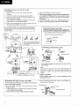
Proceed as tollows with the set-up and
connections,
1. Placethe tuner on top of the cassettetape deck
amplifier.
2. Connectthe tuner to cassettetape deck amplifier.
3. Connectthe FM antennaand the AM antennato the
tuner'santennaterminals.
l f t h e m o d e lh a sa n A M / F M C H A N N E LS T E Ps w i r c h ,
checkwhether il is posilionedproperly.
4. Attach the turntablelegsat the left and right ol the cas
settetape deck amplifier srearpanel.
5. Placethe turntableon top of the tuner.
6. Connecttheturntable'soutputcordsto the cassettetape
deckamplitier'sPHONOjacks.lf any other stereocomponentis to be used,connectit in the sameway to the CD or
VIDEOjacks.
7 . C o n n e c t h e s p e a k ecr o r d sl o t h e S P E A K E R tSe r m i n a l s .
L Finally,connectthe powercord the the AC wall socket.
Plug the power cord into the AC wall socket outlet only after all
the connectionshave beencompleted.Keepthe power switch at
the OFFposition.
Connecting tho input/output cords
a Inserlthe plugs securelyinto the jacks.lmpfoperconnectaoncan leadto sounddrsto(ionor malfunctioning.
a The white plug is for the left channelconnectionand
the red pl'rg {or the fight channelconnectron.
Be sureto insertthe plugsall the way.
White plug
mi#
eod
Red plug
Connectingt h e
strands.
(Left) S p € a k e r ( R i g h 0
.
Video disc play€.. etc
l l l u s t r a t i o nn o t a e o l i c a b l et o U . K . m o d e l .
Attaching the legs of the turntable
Attachthe legsaccompanyingthe turntableto the rearpanel
ot the cassettedeck amDlifier.
. Be sure lo attachthe left (L) and righr (R) legs to their
properposnons.
1. Insenthe guide pinson the legsinto the holesin the back
ot the cassettedeck amplitier.
2. Fastenthe legs in placewith the screwsprovided.
Checkthat the speakercords arc secure and will nt become
disconnected.
NOTE:
Do not allow the conductorsof the cods to prciect beyondthe terminals and to come into contact with other conductors. A
brcakdown or failurc may occur when conductots touch one
Speakel impedance
Connect speaker systems with a nominal impedance of between 6 and 16 ohms.
3. After connectingthe antenna,m o u n t t h e t u r n t a b l es e curelyon top ot the legs.
Turntableleg (Rl
Radio reception is not possible unless the
antenna is properly connected.
The strengthof broadcastsignalsvariesfrom one area to
another(signalpropagationis especiallypoor in metropolitan areas,where there are many tall buildings, and in
mountainousareas).Properantennainstallationis vital to
good reception.
FM ANTENNA
FM T-type Antenna Attachment
Connect the accessoryFM T-type antenna to the FM
terminals.Stretchthe antennaout to its full length,and alfix
it to a wall, etc.
Stretchout bothends.
',1
"-V
a
lrl
t
AM ANTENNA
T h e A M l o o p a n t e n n as u p p l i e dw i t h t h e t u n e r s h o u l db e
connected to the AM antenna terminals.The antenna
should be placedat a distancetrom the tuner, and should
not be allowed to touch metallicobjects.Avoid placing it
near CD players,personalcomputers,televisionsets, and
other devicesgeneratingradtofrequencies.
Setting Up the AM Antenna
. Fold out the supports on the bottom of the antenna.
Insertthe stopperin the hole in the antennato lock them
In Dlace.
. Placethe antennaon a levelsurlaceand rotaleit to locate
l h e o r i e n t a t i o tnh a t y i e l d st h e b e s tr e c e p t r o n .
AM LoopAntennaSet-up
AM Loop Antenna
Conn€ction
The accessoryAM loop antennamust be
c o n n e c l e d t o e n S u r e p r o p e r r et]]]
ceplton
f ----
ryf,:c
External AM anten na
Indoor AM antenna
Providea vinyl-coatedwire (5 to 6 meterslong). Secureone
e n d t o t h e A M t e r m i n aal n d t h e o t h e re n d t o a w a l l o r o l h e r
highlocation.
E x t e r n a lA M a n t e n n a
lf receptionis still poor evenwhen a lead antennahas been
stretchedout indoors,stretchout a vinyl-coated
wire and secureit indoors.
Connecting the external AM antenna
ill
|
|
Cored
,..-17
II
'
AlF
Wrong
Wong
The accessorvFM T-tyDeantsnna musl
be connectedro ensureproper rscep-
r
*"
t.;_'lrq
tOOCIron(
tl
|
L
:
l
External FM antenna installation
Use an externalantennawhen the signalstrom the station
are weak and cannol be pickedup by the accessoryT-type
FM antenna,or when the sound heard is accompaniedbV
largeamountsoI noise.Thereare lwo ways of connecting
t h e e x t e r n aFl M a n t e n n at o t h e A N T E N N At e r m i n a l sw: i t h
300-ohm feederwire, or with a 75-ohm coaxialcable.
It is recommendedthat you use the 75-ohm coaxialcable,
so that the effects of extraneousnoise are reducedto a
minimum.
When th€ connectingcable
is a 75-ohmcoaxialcable
75 ohmcoaxialcable 75-ohmcoaxialcable
^
A_ wrthPAL.onnector
[L_ w'thoutPAL
connecror
I
K
Y
t-\
@@(@@f@l
@16l@16l@l
When the connocting
cable is a 300-ohm
n.Tl
t€eder wrre
/,{-
3oo.ohm teeder
dIA
,-,*l@D[@T@l
AM/FM CHANNELSTEPSWITCH(F-x882
only)
This switch is not providedon modelslor use in Europe,
N o r t h A m e r i c a ,o r A u s t r a l i a (. P r o v i d e do n l y o n m o d e l s
"Z/E"
stamped
o n p a c k i n gc a s e . )
T h eA M / F M c h a n n esl t e ps w i t c hi s l o c a t e do n t h e r e a rp a n e l
o f t h e d i g i t a ls y n t h e s i z et uf n e r .B e f o r et h e t u n e rl e a v e st h e
t a c t o r yt,h i ss w i t c hi s s e tt o t h ec h a n n eal l l o t m e npt l a no t t h e
a r e ai n w h i c h t h et u n e ri s s o l d .W h e nt h e T U NI N Gs w i t c hi s
g i v e na s i n g l ep u s h ,t h e f r e q u e n cdy i s p l a yw i l l c h a n g ei n t h e
f o l l o w i n gu n i t s .
Model
d€stination
C H A N N E L S T E P Frequsncy change
switch position
FM
AM
mode
moo€
A m e f l c a a n d 1 0 0k H z / 1 0k H z
1 0 0k H z 1 0 k H z
No(h
Conlinental
America
Soulh
Olhercountries
50 kHz/g kHz
50 kHz
9 kHz
NOTE
. lf the switch is set to the wrong position, coftect tunjng
will not be possible.
NOTE:
Do not detach the AM loop antenna when using the extenal AM
Consultyour dealerif you are not sureaboutthe channel
a l l o t m e not l a ni n v o u ra r e a .
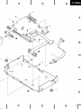
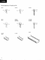
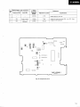
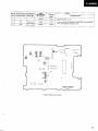
3. EXPLODEDVIEWS AND PARTSLIST
NOTES:
. Pats withoutpart number cannot be supplied.
o The A mark found on some component parts indicqtes the importance of the sofety
factor of the part. Therefore,when replacing, be sure to useparts of identicol designaOn.
o For your parts Stock ControL the fast moing items qre indicated with the marks * *
and *.
* * GENERALLY MOVES FASTER THAN *
This classification shall be adjusted by each distributor becauseit depends on model
number,temperuture,humidiry,etc
c Partsmarkedby "A" are not alwayskept in stock.Their deliverytime may be longer
than usualor thevmav be unavailable.
. hrts List
Mlrk
No,
Parl No.
D.ac.iptio|i
AMB1146
AACr006
AAD1,I07
AAKl181
AAK1189
Front psn6lassombly
Knob cap
Pu3hknob
lND. pan6l
r -L l t € r
10.
ANE1062
AMRIOO2
A8A-298
ABAlOO9
AW21247
Bonnet csse
Foot €ssembly
Scr6w
Scrow
Tun€r sasombly
11.
ADE t O24
Connection cable
1.
4.
7,
LED a$embly
Tuning assembly
Chassis
6
1
2
3
1
2
3
A
B
C
D
4
5
A
B
c
D
I
4
5
6
" [ -
@ 1
3
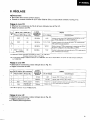
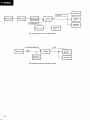
4. P.C.BOARDSCONNECTION
DIAGRAM
9P
CONNECTOR
ADE1O24
A
TUNER ASSEMBLY(AWZ1247I
I
Rch <1
GND --< 2
Lch --< 3
+12V --< 4
BACK UP +B- < 5
AC GND--<6
REMOTE CN --< 7
NC--<8
AC-<9
B
TUNINGASSEMELY
c
U
D
1
] =
2
3
'l
'
r
4
5
6
A
B
-
c
I
4
5
6
5
4
3
TUNER ASSEMBLY IAW 21247I
lC102:MPX lC
0101rFM RF AMP
O102:FM MIXER
oto2
Qtot
u.""
9-it1*.
loo0
zzq
1 C 1 0 1l 1 / 2 )
L
.J
O117:FM+B
S W I T CH I N G
*'1"""ITf,
*q:"*T:d 9--so'*
IClO].AM/FM IF DET
O104:FM LOCAL OSC
t c 1 0 1t 2 / 2 1
i
orts,neser
d
O1 16:MW +B SWITCHING
O120 LW +B SWITCHING
IC103
fr
M
Bd-
c€
1 C 1 0 3 : P L Ll C
0106, 107 Dc AMP
O] 14 TUNE IND DRIVER
IC101
IC10?
IC103
IC1O4
: LA1?65S
: AN7470P
: LM700r
: P05O47
0rO1
oto?
oro3,1o4
OlO5
Q1O6
O1O7
0roa, to9,
Ollt
O11o
:
:
|
:
:
:
?X241
2SC2786
2sc266€
2SXl6l
2SX246
2SC|T4OSLI
:
:
2SC174OS
2SA933s
0112,113
0r14,1r6,
oll7,12o
Q115,121
Q1ta,119
| DTC143ES
: oTA143€5
: DTC124ES
: 2SC2878
: lTT3ro
0ro1,1o2
DtO3,1O4,lO9 : SVC321C3 6r
svc32103
0lo5-1o4,
0 r r 1 , 1 1 3 ,f l 4 ,
0118-t2l
: lSst31
D110,501
: R07.5€SE
D112
: R06.2ESB
Dll6.1l7
: lSSa5
L RESIST0RS,
lndicoted in o. vaw. v4w,15x
loteronce untess olherwise noled
k; ko. M; Mo. (F):11x. (G)r izx.(K): rlox. (M)r 12ox toteronce
2,
CAPACITORS:
hdicoled
in copocity (fF)/vottoge
pr pF. Indicolion withoul
(V) unless oiherwise
vottoge is 5OV excepl
etecirotyiic
f,. VOLTAGE. CURRENT:
lf;
E
n0lad
copocilor
5
4. OTHERS:
{ : s l g n o (r o u i e .
O : Adjusthg polnl.
The A mork tound on some componentporls Indlcolesthe lmporlonce
of the solely locior of lhe porl. Theretore. when reptoclng.be sure
lo use pdris of ldenllcoldeslgnollon.
horked copocllorsond reslstors hove porTs numbers.
Thls ls the bdslc scienotlc dlogron.bul lhe octuot clrcult moy vory due
lo lhprovemenlsIn desl9n.
DC votloge {V) ol no inpul siqnot
,signot votlooe 01 FM 4ooHz 75kHz DEV.
3
1C104:TU
MICR
" : . : : : : : E a 3 ! 3 o 3 ! € g s t g t ! s I - li a g t "
3
. Y T Y Y Y Y Y Y Y Y Y Y Y Y Y Y Y Y Y Y Y ; Y YY
]
4
SW|TCHES:
:
:
:
:
I /13
?/14
J/15
4/16
s105 : 5/17
s106 | 6/14
S1O7'7/19
s10a I a/20
s109 : 9/21
s110 . ,o/22
: l1l23
Sfl
s112 . 12/24
s101
s102
s103
s104
s50r
s502
1-12/13-24
FM MdO
s40r
s402
s405
s404
'UNINC TUNING +
BArc SELECIOR
5
5
7
6
O ] 0 8 , 1 0B
9UFFER
r c 1 0 2M P Xr C
9P CONNECTm
aElo24
1 C 1 0 1l 1 / 2 1
lH I
IFG;- i** itn*''"'""
,"?-fd?i
' + l
^
or ro vurt
"1.r2rc
|
"""7
rCtr2
+WT€
ICIO4
6?t8h
rdo
0 1 ] 4 T U N EI N D D R I V E B
o114
rcr04.ruNEacoNrBoL('il/-MICROCOMPUTEY
F o!13
"33€sststls*5!":C"
Y Y Y Y Y Y Y Y Y Y Y
5.
hportcnce
hg. De sure
moy vory
due
g
Y
)E
I
SWITCHES:
:
'
:
:
:
:
s107 |
s10a :
S$9 :
sao |
:
Sfi
511? .
stot
s102
srcf
Src4
Sp5
SP6
I /15
2/14
5/15
4/16
5/17
6/14
7/19
a/20
S3O1 : l-12113-24
S3O2 : FM MdO
S4O1 : TUNNC 5402: rUNNG +
s4O3 : EMmY
s4O4 : BANo SELECTOR
9/21
10/22
r/23
1?/?4
LED ASSEMBLY
5
6
TUNING ASSEMBLY
7
of Transistors
and l0s
ExternalAppearances
2SC2878
2SC2786
Type No
2 S K 16 1
25K241
25A933S
2SC17405
2SC17405LN
DTA143ES
DTCl 24ES
DTC143ES
Type No
Lot No
hre
AN747OP
LM7001
LA12655
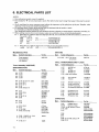
6. ELECTRICAL
PARTSLIST
NOTES:
. Partswitho paft number cannotbe supplied.
. Parts marked by "A" are not always kpt in stock. Their delivery time may be longer than usual or they may be unavailable.
o The A mark found on some component parts indicates the importance of the safetyfactor of the paft. Therefore, when
replacing be swe to useparts of identical designation.
c For your parts Stock Control, the fast moving items are indicated with the marks * * ond * .
* * GENERALLY MOVES FASTERTHAN*
This classification shall be adjusted by each distibutor becauseit dependson model number, temperature,humidiry, etc.
c Whenordering resiston,fnt convert resistancevaluesinto codeform as shown in thefollowing exqmple'
Ex. I Whenthere qre 2 effectivedigits (any digit apa ftom 0), such as 560ohm and 47k ohm (tolerance is shown by l 5%,andK-10'%).
5flA
56x t0t
5 6 1 . . . . . . . . . . . . . . . . . .R. .D. .l./.4. .p 5 6 @ m J
17kA
47 x 10r
4 7 3 . . . . . . . . . . . . . . . . . .R. .D. .t./.4. .p s @ A 6 J
0.59
0R5...............................................RN2HO8trK
1A
01o.........................R
. . .s./.P
. .o.t.r.@
. .K
...........
Ex. 2
Whenthere are 3 effectivedigits (such as in high precision metal frlm resistors).
5.62k4 562x 101 5621........................
RN1/4SR
6 6 E tr l.
Parts
Miscellaneous
M.rk
Symbol & D.scription
Tuner asseftboy
Tuning alsembly
LED assembly
s1,l[TcHES
Part No.
Merk
r r
AWZ1247
Symbol&Descriplion
Prrt No.
SlOl - Sl'12 Tact switch
{STATION)
ASG.712
COILST
, R A N S F O R M E RA
SN D F I L T E R S
M.rk
Tu ner Assembly(AW21247|
SEMICONDUCTORS
M..k
Symbol& O.scription
P.rt No.
*t
r*
* *
**
tc102
tc101
rc103
tcr04
AN747OP
LA12655
Ll\,17001
PD5047
It
r*
r t
ri
rr
0 1 ' t 4 ,0 1 1 6 ,0 1 1 7 ,0 1 2 0
o 1 1 5 ,O 1 2 l
0 1 1 2 ,0 1 ' t 3
01.to
0 1 0 8 ,0 1 0 9 ,0 1 1 1
DTA143ES
DTC124ES
DTCI43ES
2SA933S
2SC17405
r*
t r
*t
rt
*t
0107
0103, 0104
0102
0 1 1 8 .0 1 1 9
0105
2SC17405LN
2SC266a
2SC27A6
2SC2878
2SK16'l
0101
0106
2SK241
2SK246
D 1 0 1 ,D 1 0 2
D ' t1 2
D 1 1 0 ,D 5 0 1
D103,0104, D109
tTT310
RD6.2ESB
RD7.5ESB
r*
**
r
t
*
*
svc32lc3
(svc321D3)
*
*
D 1 0 5- O ' t 0 8 D
, l11, D113,
D 1 1 4D
, 't18- D121
1SS131
r
0 1 1 6 ,D l t 7
1SS85
Symbol & DGcrifiion
P.rt No.
L107
AM OSC coil
FM coil
L102
L110
LW OSC coil
L1O5
F M D E Tc o i l
L101, L108 Axial inductor
ATB.,I14
ATC1003
ATD-023
ATE-079
LAU2 R2IVI
Ll09
L106
Axial inductor
Inductor
LAU221K
LT 4472J
T103
T101
T104
f 102
AM
FM
LW
FM
ANT transtormer
RF trsnsformer
ANT transformer
malching transformer
ATB,O95
ATC-194
ATD 1OO2
ATE463
F103
F 102
F1 0 1
F1 0 4
FM
FM
FM
AM
ceramiclilter
c€ramictilter
b a n d p a s sf i l t e r
cer€mic filter
ATF-107
ATF-119
ATF.I55
ATF.2OA
CAPACITORS
Symbol & O..criprion
Psn No.
Cl63
{22oo0pF/5.5V)
TCl03
Ceramic
trimmer
TC101,TC102Ceramic
trimmer
clr6, c181
cl13
ACH1023
ACM.020
ACM426
cccsL101J50
ccDcH0loc50
c106
c101
clll
cl08, clr4, c't59,cl60, c174
cl69, Cl70
ccDcH020c50
ccDcH040c50
ccDcHo80D50
ccocHl50J5o
ccocH270J50
Symbol & Oercrifiion
Part No.
OTHERS
cl to
c176
cl04
c107
c128
ccDcH330J50
ccDcH560Js0
ccDRH 180J50
ccDsLl0'tJ50
ccDsL221J50
tla.k
cl09
c117
cl30
cl46
c182
ccDTH150J50
ccDUJ120J50
CEANPO'IOM5O
CEASR22M5O
cEASORt M50
c ' t 4 1c, l 5 5 ,C l 5 7 ,C l 7 1 ,C l 7 9
c121,C145
c164,Cl65
cl80
c124,Cl6t, C't68
cEASO10M50
CEASlR5MsO
cEAS100M25
cEAS101M10
c E A S l 0 lM 1 6
cr39, cl50, c151
c134,C144
c122,C127,C131
cl35
cl36, C166
CEA52R2MSO
CEA53R3M5O
cEA5330M16
CEA54RTM5O
cEA5470M10
cl54, Cl56
cl44, cl49
cl3a
c r 5 2 ,c l 5 3
c l 1 9 ,C 1 3 2C, 1 4 0
cEA5470M16
cKcYB102K50
cKcYB222K50
cKcYB332K50
cKcYF 103250
cKcYF223250
cKcYF473250
cKcYX473M25
C K D Y B1 0 2 K 5 0
cl02, cl03, c105, c123, C172,C113 CKDYF103250
cl 15, Cl25, C f 26, C129,C176,C178 CKDYF223Z50
cKDYF473Z50
cosA301J50
cosA431J50
cosA471J50
cKDYFI 03250
RESISTORS
Mtrk
t
Symbol& Oarctiptiofn
Prrt No.
VR101
VRTB6V5472
S€mi-fixed 14.7kc))
R226
RO112PM220J
R 162,R f 67, Rl68, R l70,A171,R225RD1l4P[,ltrtr trJ
Other resistors
Prrt No.
A n t e n n a t e r m i n a l ( 4 P ) ( P A L ) AKAlOO2
*
t
t
V101
X102
X101
F l u o r e s c e n tt u b e
Ceramic resonator
Crystel rosonator
AAV-017
ASS-O30
ASS1005
TuningAssembly
SEMICONDUCTORS
Mark
*
*
Symbol&Deacription
P.rt No.
O4O2
D401
AELlOO9
AEL1024
LED assembly
LED €ssembly
S:WITCHES
cl20
c133,Cl43,Cl47
c137
c112
cl 58,cl62
c177
c'tl8
c142
c183
Symbol & D.scriplion
RDl /8PMtrtr OJ
M!.k
Symbol&O.scriplion
r t
Prrt No.
3401 - S4O4 Tact switch
ASG-7 r 1
/TUNTNG-T
, U Nr N G + l
\ M E M o R Y .B A N D
l
RESISTORS
Mark
Symbol&Description
Part No.
R401
RD1/8PM332J
LED Assembly
SEMICONOUCTORS
Merk
*
Symbol& Descripiion
Part No.
D3O1,D3O2 LED assembly
AEL1O24
swtTcHEs
M.rk
t t
Symbol & D..cription
Parl No.
5301,5302 Tact switch
( F M M O N O ,S T E RE O )
ASG-71'l
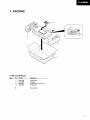
7. PACKING
. PartsList of Packing
M..k
No.
1.
4.
5t.
P.n No.
Oaacription
AHD,I164
AHA1O45
ARH.Os1
AEAIOO2
Packingcase
Side p.d
Supplomentrryinstr!ctions
Antonna s6t
Packingrhoet
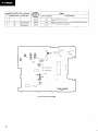
8. ADJUSTMENT
PREPARATION
o ConnectTP15(cND) with TP17(GND).
r SupplyDC 12V betweenTP18andTP17,and betweenTP13andTP15 (seeFig.8-1).
FM TunerAdlustment
o Makethe wire connectionsasshownin Fie. 8-2.
r Setthe function to FM.
Step
No.
F M S G { 1 k H z t 7 5 k H zd e v . )
F.X88ZL
Reception
Frequency
Display
Frequency(MHzl
Level{dB/)
98.0
60
98.0MHz
1105
Adjust so that DC voltageis 0V t 0.1V for TP28
(TMETER
1 ) a n dT P 2 6l T M E T E R
2).
98.0
60
98.0MHz
T 1 0 1, T 1 0 2
Adiust the output terminal(TPs: L ch, TP7: Rch)
voltageto the maxjmum.
9 8 .O MH z
VRlOl
GroundTP25 throughthe 22OlF capacitor,and
adjustthe frequencyof TP8 ro 76kHz 12O0Hz.
9 8 .O MH z
r102
Adjust the output terminal{TP5:Lch, TP7: Rch)
distonionto the minimum.
l
2
('3)
3
4
Adjustm€nt
^^ ^
'1 (slereo
60
Adjustment Location
Specifications
{ ' 1 ) S t e r e o M o d u l a t i o n :M a i n l k H z L + R i 6 8 . 2 5 H 2 d e v .
Pilot lgkHz t 6.75kHz dev.
{ ' 3 ) T h e m e t h o d o f a d j u s t m e n t i n s t e p 2 i s d i f f e r e n t f o r F - x g g Z l Z E Z r y p e . F o r d e t a i l s ,r e f e r t o s e r v i c em a n u a l ( A R p 1 3 4 1 ) f o r t v o e
F-XaAZIZEZ.
MWTunerAdjustment
o Makethe connections
asshownin Fie. 8-3.
. Setthe functionto MW.
Step AM SG (400H2,30%modulation)
No.
FrequencylkHz) L€vel {dBp}
1
F-X88ZL
Reception
Frequency
Display
53lkHz
'I602kHz
2
3
603
4
r395
Levelat which
output is not
saturated.
( ' 2 ) F 1 0 4 i s a d j u s r e df o r F - X 8 8 2 / Z l O X l B
603lHz
1395LHz
tvpe.
LW Tuner Adiustment
o Make the connectionsas shown in Fie. 8-3.
o Set the function to LW.
. F-XSSZLIZEB type only.
Adiustment
Adjustment Location
Specilications
1107
Adjust TP3 (VT) to 1.3V 1O.'l V.
TC102
A d j u s tT P 3 { V T )t o 1 O V 1 0 . 5 V .
T 1 0 3( ' 2 )
T C r 0 l ( *2 )
Adjust the output terminal(TP5: L ch, TP7: R ch)
voltageto the maximum,
itep AM SG l4OOHz,3Oo/omodulationl
N o . Frequency(kHzl Level (dBrl
1
2
164
?
254
Level at which
output rs not
saturated.
F-X88ZL
Reception
Frequency
Display
Adjustment
Adjustment Location
Specifications
281kHz
L 11 0
Adjust TP3 (VT) to 5.2V.
164kHz
T 10 4
254kHz
TC103
A d j u s tt h e o u t p u tt e r m i n a (l T P 5 :L c h , T P 7 : R c h )
voltageto the maximum.
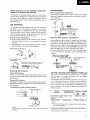
rP1.(GND)
o q o-"''
o
\
rP17{GND)
\
L'o5[sI
o
1rc7[o
TUNER
ASSEMBLY
I AWZ\247\
F i g .8 - 1 A d j u s t m e npt o i n t
OUTPUT(L, R}
I *,--, L_j
I
counter
I
t@
Fig.8-2 FM Tuner Connection
AM antennaterminal
Fig.8-3 AM Tuner Connection
20
8. REGLAGE
PREPARATIFS
o RaccorderTP15 (Tene)ri TP17(Tene).
. Fournirun courantcontinude 12 V entreTP18 et TP1?,et entreTPl3 et Tplb (voir Fig. 8-1).
Reglage
du tuner FM
o Effectuerles connexionsdesfils de la fagonindiqu6edansla Fig. 8-2.
. R6glerla fonction sur FM.
FM SG {1kHzt 75kHz d6v.l
F16qu€nce
lMHz) NiveauldBpl
1
( -3 )
F.X88ZL
Attichago de
fr6quence de
16c6ption
Rdglage
Lieu d€ r6glage
Caract6ristiques
98,0
60
98,OMHz
1105
98,0
60
98.0MHz
T 1 0 1T
, 102
Ajusterla tensjonde la bornede sortie (TPs:canalgauche,
TP7: canaldroit) au maximum.
98,0MHz
VR1O1
Mettre a la terreTP25 en passantpar le capaciteurde 22O lF,
et ajusterla lr6quencede TP8 a 76kHz !2OOHz.
r102
Ajusterla distortionde la bornede sortie (TP5:canalgauche,
TP7: canaldroit) au minimum.
3
98,O * 1 (modu
lationst6r6o)
60
98,OMHz
Aiusterde telle fa9on que la tensionCC soit de OV a 0,1V
pour TP28 (TMETER1) et TP26 (IMETER2).
('1) Modulatjonst€r6o:D€viataon
principalede I kHz G + D 168,25H2
D6viationpilotede lgkHz a 6,75kHz
('3) La mithode de rdglage
d l'drape2 diffdrepour le F-X88Z|ZEZ.Pourde plusamplesd6tails,sereporterau mod€d'emploi(ARPl341)
du F-X8SZ|ZEZ.
Reglagedu tuner MW
r Effectuer les connexionscommeindiqu6 dansla Fig. 8-3.
o R6glerla fonction sur MW.
Etape AM SG l/rOOHz,30%modulationl
Fr6quence(kHzl Niveau (dBrl
1
531kHz
2
3
4
F-X88ZL
Aftichage de
tr6quence d6
.6ception
603
Niveauauquel
la sortie n'est
pas saturee.
R6glage
Lieu de .6glage
L1 0 7
1602kHz
TCr02
6O3lHz
T 1 0 3( *2 )
1395kHz
T Cr 0 1 ( . 2 )
l'21 F104esrr6gldpour le type F.X88Z/Z|OX1B.
R6glage
du tuner LW
. Effectuer les connexionscommeindiqu6 dansla Fig. 8-3.
r R6glerla fonction sur LW.
. F -X88ZLI ZEB uniquement.
Caract6ristiques
AjusterTP3 (VT) sur 1,3V t O,1V.
A,usterTP3 {VT) sur 'l0V a0,5V.
Ajusterla tensionde la bornede sortie {TP5:canalgauche,
TP7: canaldroit) au maximum.
Etap6 AM SG l4OOHz,30%modulation)
Fr6quence{kHzl Niveau(dBt)
2
164
3
254
Niveauauquel
la sortien'est
pas saturde.
F-X88ZL
Atfichage de
fr6qu€nce de
r6ception
Reglage
Caract6ristiques
Lieude 169lage
281kqz
Ll10
AiusterTP3 (VT) sur 5,2V
164kHz
T104
254kHz
TC103
Ajuster la tensionde la bornede sortie(TPs: canalgauche,
TP7: canaldroit) au maximum.
Fig.8-1 Positionsde 169lage
22
S O R T I E{ G , D }
Borne d'antenne FM
de 300 ohms
l-.*L_l
detr6quence
I
I
I
Ll
r-t
I
d u t u n e rF M
F i o . 8 ' 2C o n n e x i o n
Borne d'antenneAM
Fig.8-3 Connexiondu tuner Al\4
vor,.e,'"I
numeque
I
8. AJUSTE
PREPARATIVOS
o ConecteTP15(mam)con TP17 (masa).
r Aplique12V CC entreTP18y TP1?,y entreTP13y TPJ.5(consultela Fig. 8-l).
de FM
Ajustedel sintonizador
o Realicelas conexionescomo semuestraen la Fig. 8-2.
. Pongael selectorde funci6n en FM.
Ajust€
F M S G l 1 k H 2 1 7 5 k H zd e v . ,
F-X88Zt_
Frecuenclm€trode
paso Frecuancia
lMHzl Nivel {dBpl
recepci6n
2
4
Aiuste de forma que la tensidnde CC sea de 0V 10,1V para
2).
T P 2 8 { T M E T F F1 ) y T P 2 6 I T M E T E R
9 8 . 0 MH z
T 1 0 1 ,T 1 0 2
Aiuste la tensi6ndel terminalde salida(TP5:canalizquierdo,
TP7: canalderecho)al m6ximovalor.
98,OMHz
VRlO1
98,0MH2
r 102
60
98,0MHz
98.0
60
98,0 * 1 (modulaci6n est6reo)
60
Esoecilicacionog
1105
98.0
3
('3)
Luga.
de aiuste
PongaTP25 a masaa trav6sde un c apacitotde 22O tF, y
ajustela lrecuenciade TP8 a 76kHz l2OOHZ.
Ajuste la distorsi6ndel terminalde salidalTP5r canalizquaerdo, TP7: canalderecho)al mlnimoest6reo)
(* 1i Modulacidnest6reo:Prancipal
l kHz canal izquierdo+ canalderecho ! 68,25H2 de desviaci6n
Piloto 1gkHz l6,7skHz de desviacidn
(*3) El m6todode ajusledel paso2 esdiferenteparael ripo F-X88Z|ZEZ.Con rcspec\oa losdetalles,
consulteel manualde servicio
(ARP1341)parcel ripo F-><882/2E2.
de MW
Aiustedel sintonizador
o Realicelas conexionescomo semuestraen Ia Fig. 8-3.
o Pongael selectorde funci6n en MW.
AM SG i4ooHz.30% modulation)
paso Frecuencia(kHzl
Nivel ldBrl
F-X88ZL
Frecuencimotro
de recepci6n
a j u s t e T P 3l v T ) a 1 , 3 V 1 0 , 1 V .
1602kHz
TC1O2
AiusreTP3 (VT) a loV I o,5V.
603kHz
T 1 0 3t * 2 )
1395kHz
T C1 0 1 { * 2 )
531kHz
2
4
603
Nivelen el
que la salida
no se satura
( * 2 ) F 1 0 4s ea j u s t a
p a r ae l t i p o F - X 8 8 2 / Z l O X 1 B .
Ajuste del sintonizador de LW
o Realice las conexiones como se muestra en la Fig. 8-3.
o Ponga el selector de funci6n en LW.
r Tipo F-X88ZL/ZEB solamente.
24
Especiticaciones
1107
1
3
Aiuste
Lugarde
ajuste
Aiuste la tensidndel terminalde salida(TP5:canalizquierdo,
TP7: canalderecho)al m6ximovalor.
F-X8aZL
Uo.do AM SG l4OOHz,30%modutarion)
Frocuencimetao
paso Frecuencia
lkHzl Nivel ldBrl
de recepci6n
1
2
164
3
254
Nivelen el
que la salida
no se satura
281kHz
'164kH2
254kHz
Ajuste
Lugarde
aiuste
Especiticaciones
Ll10
Ajuste TP3 (VT) a 5,2V.
T1 0 4
Ajuste la tensi6ndel terminalde salidaTP5: canalizouierdo.
TP7: canalderecho)al rndximovalor.
TC103
a,ou
@
o
a,otQ
Fig,8-1 Posiciones
de ajuste
Salida(Canal izquierdo
y derecho)
Terminal de antena de
FM de 3O0 ohmios
@,
,@
Fig.8-2 Conexiones
del sintonizadorde Fl\4
r Terminal de antenade AIM
Fig.8-3 Conexiones
del sintonizadorde AM
ADVARSEL
ADVARSEL!
Eksplosionsf
are.UdskittLithiumbatteri.
ningma kunloretagesaf en sagkyndig,
i servicemanualen.
og sombeskrevet
Derme advarsel or angivet pa produktet €ller i
brugsvejtedningen. Ved udskiftning af lithium
baneriernefolgesnedensldendeanveisning.
Batteriemema kun udskiftesmed batterieraf
sammetype og m@rke.
WARNING!
Lilhium batteries.Danger of explosion.
Replacementmust be done by qualffied
personnel and only by following the
instructionsgivenin the servicemanual.
This waning is stated on the product or in the
operating instructions. When replacing the
lithium batteries, follow the note below.
The batteries must be replaced only by batteries of the samelvDeand manufacrure.
27