1
RSP1 Evaluation Kit
User Manual
© RFbeam Microwave GmbH www.rfbeam.ch
Page 1/18
Preliminary User Manual
RSP1 Evaluation Kit
Features
Reference design for RFbeam RSP1 processor
Advanced movement detection system
High performance signal processing
More detection range than traditional designs
Less susceptibility to interferences
Supports most RFbeam Radar transceivers
Stand alone or host operated modes
Analyzing and command software tools included
Saves time to market and development investments
Applications
Reference design for own developments based on RSP1 processor
Exploring FFT based Dopppler signal processing
Optimizing choice of sensor type for different applications
Overview
RSP1 Evaluation Kit is a fully operational movement sensor application using advanced signal
processing. It saves an important amount of
evaluation and development time and money.
The RSP1 processor offers adaptive noise
cancelling and automatic adaptation to different
Doppler transceivers.
Functionality can be influenced by manual settings
as well as by more than 30 parameters and
commands.
The kit can be used as stand alone system or as a
server of a host computer or microcontroller.
The kit contains helpful software tools for configuration and signal visualization.
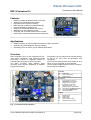
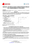
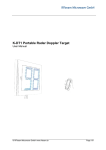
Indicators
D1
D2
D3
Power LED
Busy LED (start-up)
Detection LED
Connectors
X1
X2
X3
X4
X5
X6
X7a
X7b
Xp
K-LCx sensor connector
Backside K-LCx connector
K-MCx sensor connector
Digital output connector
DC Supply input 6 .. 12V
Digital I/O (SPI in preparation)
Serial Command (RSP_Terminal)
Serial Debug (RSP_Scope)
Reserved / Reset
Settings
P1
P2
SW
J1
J2
Sensitivity pot
Hold time pot
Mode switch
Sensor supply volage
Optional for mono sensor
Fig. 1: Connectors and indicators
© 2014 RFbeam Microwave GmbH www.rfbeam.ch
Page 2/18
RSP1 Evaluation Kit
Preliminary User Manual
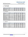
Packing List
1. Eval-Kit PCB board
2. RS232 USB cable
3. USB stick containig
RSP_Terminal software, RSP_Scope software, FTDI USB-Serial drivers
Documentation
4. 5 different RFbeam Radar sensors:
K-LC1a, K-LC3 (1 channel sensors, also called "mono sensors")
K-LC2, K-LC5, K-LC6 (2 channel sensors, also called "stereo sensors", "I/Q sensors")
Getting Started
Preparation
We will begin with using the Evaluation Kit as stand-alone device without any PC software.
Please follow step by step:
1. Install software from USB stick by starting "setup.cmd"
Different software modules will be installed. If your computer does not already contain the actual
LabVIEW runtime engine, you will be asked to accept licenses of National Instruments. Please
accept all default storage locations. Several installers are executed by a script. Accept installers
until the end of complete installation.
2. If correctly installed, You will find RSP_Terminal and RSP_Scope software under
START-PROGRAMS-RFbeam-RSP and the program Icons on your desktop
3. Connect the FTDI USB cable to PC. Leave RSP side connector unplugged!
FTDI Hardware should be recognized by Windows after some seconds.
Unplug USB cable from PC again so that power of the kit is off
4. Insert the K-LC2 sensor in RSP_Evaluation-Kit front connector X1
5. Set 'SW' DIP switch '1' in ON position, all other should be OFF:
1
2
3
4
5
6
ON
6. Set Potentiometer P1 (sensitivity) to maximum (towards +)
7. Set Potentiometer P2 (hold time) to minimum (towards -)
Always unplug power supply befor inserting or unplugging sensors
RFbeam K-LCx radar module are susceptible to electrical discharge . Before plugging the
module, please touch first the RSP1 board and then insert the K-LCx device.
© 2014 RFbeam Microwave GmbH www.rfbeam.ch
Page 3/18
Preliminary User Manual
RSP1 Evaluation Kit
Quick Start
No PC software is required yet.
1. Plug in USB cable into X7a (black wire must be connect to pin '1')
2. Plug in USB cable into a USB port of your PC or notebook. This serves as power supply now.
3. Look at the LED indicators
- D1 power LED is on
- D2 busy LED turns on for about 5 seconds: RSP1 is learning the sensor and environment.
4. RSP1 is ready, as soon as red D2 is off
RSP1_Eval-Kit can also be used without a PC and USB cable. Use a 12VDC adapter or a 9V
battery connected to the X5 power supply connector instead.
Explore!
You have plugged in a K-LC2 "I/Q stereo" sensor. This allows distinguishing between movements
towards and backwards from the sensor. (This behavior can be changed by other DIP switch settings).
→ Forward movement;
Green indicator LED3 turns on only, if there is a forward movement to the sensor.
Walk around in some distance from the sensor and check this.
→ Sensitivity potentiometer:
This affects the maximum detection distance. May be that there is no more reaction near the
minimum sensitivity. This behavior depends on the sensor type.
→ Hold time potentiometer.
Turn it to the center position: hold time will be around 5 seconds. Maximum hold time is around
160 seconds.
→ Direction settings;
Set sensitivity to maximum and hold time to minimum again to get best experience.
Set switches to explore detection modes:
"Mono":
detects movement
in both directions
1
2
3
4
5
6
ON
"Backwards":
detects movements away
from the sensor only
1
2
3
4
5
6
ON
→ Try other sensors and settings:
Refer to Switch Settings Summary.
Always unplug power supply befor inserting or unplugging sensors.
Do not try to connect any device on X2 component side!
Connector X2 is for connecting sensors on the backside of the Evaluation Kit only.
© 2014 RFbeam Microwave GmbH www.rfbeam.ch
Page 4/18
Preliminary User Manual
RSP1 Evaluation Kit
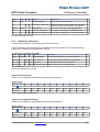
Switch Settings Summary
Settings and around 30 parameters can be set and permanently stored by an ASCII terminal connected
via the command interface at X7a. Please refer to the RSP1 data sheet for more information.
For stand alone operation, most important parameters my be set by potentiometers and a DIP switch.
Mode Switch 'SW'
Changes becomes valid only after power up.
Switch #
Function
ON
OFF (default)
1
Sensitivity / Hold Time
Use potentiometers
Use EEPROM Sensitivity/Hold settings
Switches 2 … 5 take only effect, if switch #6 is in ON position
2
Sensor type
Mono sensor (K-LC1 e.g.)
I/Q sensor (K-LC2 e.g.)
3
Direction mode
Mono (even with I/Q sensor)
Stereo (=Directional)
4
Direction
Backward
Forward
5
Immunity
Higher interference immunity
Low interference immunity
6
Select Setting mode
Use switch 2 … 5 settings
Use EEPROM Mode settings
Typical Settings
These examples assume standard default parameters in EEPROM. For more information on EEPROM
parameters refer to the RSP1 datasheet.
Switch #1 defines, if potentiometers for sensitivity and hold time will be active or if fix values will be used.
Switch #6 enables settings of switches #2 .. #5.
Configuration
Switch Setting
Use Potentiometers
1
2
3
4
5
6
1
2
3
4
5
6
1
2
3
4
5
6
1
2
3
4
5
6
1
2
3
5
6
ON
Manual settings inactive
ON
Manual settings active
Typical directional setting
ON
Manual settings active
Typical non directional setting
with I/Q stereo sensor
ON
Manual settings active
Typical non directional setting
with mono sensor
4
ON
© 2014 RFbeam Microwave GmbH www.rfbeam.ch
Remarks
All parameters from EERPOM except potentiometers. Defaults:
- I/Q stereo sensor (K-LC2, K-LC5, …)
- Direction forward
All parameters from EERPOM. Defaults:
- Maximum sensitivity
- Minimum hold time
- I/Q stereo sensor (K-LC2, K-LC5, …)
- Direction forward
Most important parameters manually set:
#2: I/Q stereo sensor (K-LC2, K-LC5, …)
#3: Direction mode stereo
#4: Direction forward
#5: Standard interference immunity.
Most important parameters manually set:
#2: I/Q stereo sensor (K-LC2, K-LC5, …)
#3: Direction mode mono
#4: Direction forward
#5: Standard interference immunity.
Most important parameters manually set:
#2: Mono sensor (K-LC1, K-LC3)
#3: Direction mode mono
#4: Don't care
#5: Standard interference immunity.
Page 5/18
Preliminary User Manual
RSP1 Evaluation Kit
Using RSP Software Tools
RSP_Terminal software allows viewing and changing RSP parameters via serial interface on
connector X7a. Optionally, it can also be used on connector X7b.
RSP_Scope software allows viewing internal signals via serial interface on connector X7b.
Consult the RSP1 datasheet for more detailed explanations on signal processing
RSP1 tools use an FTDI cable virtual com port cable (TTL-232R-3V3 ) from www.ftdichip.com.
Drivers have been installed automatically together with the RSP1 tools installer.
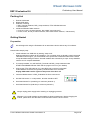
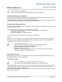
Locating the Serial Port
Please connect the FTDI cable to a USB prot of your computer.
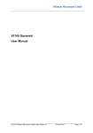
When starting an RSP1 tool, a com port dialog appears:
Normally, the highest COM port number is the right port.
To be sure, please unplug and replug the USB cable during this dialog.
The related port number will disapear and apear again.
The RSP tools will remember the selected port.
Fig. 2: Connection Dialog
RSP_Terminal
RSP1 processor can be influenced by many parameters. RSP_Terminal allows viewing and setting all
parameters. In fact, RSP_Terminal emulates a host computer or microprocessor used in a RSP1 based
user hardware.
Establish Connection
Establish connection:
1. Connect serial cable to Eval-Kit connector X7a
2. Connect serial cable to USB port of you PC
3. Start RSP_Terminal software
4. Select Port at baudrate 38400.
5. Press OK
Check if connection works:
Type command $R04 ("get RSP1 version")
→ Example Response @R0413 (Version 1.3)
© 2014 RFbeam Microwave GmbH www.rfbeam.ch
Page 6/18
Preliminary User Manual
RSP1 Evaluation Kit
Entering Commands
RSP1 follows a client-server protocol. RSP1 is the server that executes the client (Host/PC) commands.
Some rare exeptions exist when executing loop commands.
All parameters of classes 'A' and 'S' are stored in the permanent EEPROM memory.
Command Syntax
Read parameters:
Write parameters:
Command $A02<ENTER>
Command $A0203<ENTER>
→ Response @A0209
→ Response @A0203
Example read command
Explanation
$A02<ENTER>
$:
A:
02:
Enter:
command identifier
command class
2 digit hexadecimal parameter number
Enter key (or <CR> or <CR><LF> code)
@:
A02:
09:
CRLF:
response identifier
command confirmation
actual 2 digit value (typically hexadecimal)
codes for "carriage return-line feed"
$:
A:
02:
03:
Enter:
command identifier
command class
2 digit parameter number
2 digit new parameter value (typically hexadecimal)
Enter key (or <CR> or <CR><LF> code)
@A0203<CR><LF>
@:
A02:
03:
CRLF:
response identifier
command confirmation
2 digit value confirmation (typically hexadecimal)
codes for "carriage return-line feed"
Example read command
returns a string
$R10
Get firmware version string
Example response
@A0209<CR><LF>
Example write command
$A0203<ENTER>
Example response
Example response
@RFbeam RSP1 Version V1.4
Sep 19 2014
String responses are marked in parameter table with *
You may repeat a command by simply typing $<ENTER>
© 2014 RFbeam Microwave GmbH www.rfbeam.ch
Page 7/18
Preliminary User Manual
RSP1 Evaluation Kit
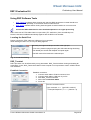
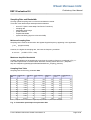
Most important Parameters and Commands
For complete parameter list please refer to the RSP1 Data Sheet
Param.
default min max Function
Description
Class A
(EEPROM)
Application Parameters
End-User specific settings in final application
A01
01
00
09
hold time
9: maximum hold time of detection output
A02
09
00
09
sensitivity
9: maximum detection sensitivity
A03
03
00
09
immunity
9: maximum immunity against interference
A05
00
00
02
direction
0: approaching; 1: receeding; 2: both
Class S
(EEPROM)
System Parameters
Application specific parameters
S00
00
00
01
sensor type
0: stereo I/Q sensor; 1: mono sensor (1 channel)
x
S01
00
00
01
Use alternate analog port
1: ADC input on pin 2 and 3 instead of pin 44 aqnd pin 1
x
S03
02
01
0A
sampling rate
see Fig. 11
x
S08
01
00
01
bandwidth
1: low bandwidth (digital output used for external filter)
S09
04
00
04
ADC gain
gain = 2^n: 0 -->1; 1-->2; 2-->4; 3-->8; 4-->16
x
S0C
02
00
FF
Adaptive learn speed
0: maximum; >0: value * 500ms/dB
x
Class R
(immediate)
Real-Time Read Params
Read only parameters
R00
-
00
01
detection active?
1: detection output active (includes hold time)
R01
-
00
FF
detection speed
0: no peak position (FFT bin #)
0
FF
noise level mean
arithmetic mean over all FFT bins
R02
R
R04
-
00
FF
software version
major.minor version (x.0 are preliminary versions)
R10
*
--
--
software version string
Full software version and date string, max 40 characters
R11
*
--
--
result string on serial cmd port SpeedFW, SpeedBW, MagFW, MagBW<CR>
Class W
(immediate)
W00
-
00
W01
-
-
W02
-
Class L
(LOOP)
L00
-
Real Time Write Params
Volatile write parameters
01
force detection output
1: set digital detection output; 0: normal output operaton
-
reset processor
software reset. value has no effect
-
-
load default parameters
load default values for all parameters
Continuous output
Output results continuously until $<CR> is received
-
-
result string on serial cmd port SpeedFW, SpeedBW, MagFW, MagBW<CR>
Note: Column “R”: Reset required
Restore original default parameter values with command $W02
Repeat a command by simply typing $<ENTER>
© 2014 RFbeam Microwave GmbH www.rfbeam.ch
Page 8/18
Preliminary User Manual
RSP1 Evaluation Kit
RSP_Scope
This tool is a virtual oscilloscope and shows internal amplitude vs. speed signals. It also shows I and Q
time domain signals.
All signals including FFT are processed by RSP1 chip and are sent via high speed serial interface.
RSP_Scope does only scale some values, but does no signal processing.
- RSP_Scope must be connected to connector X7b at 460800 Baud.
- All explanations assume a K-LC2 sensor and RSP default parameters.
Establish Connection
Please refer also to chapter Locating serial PC port.
Establish connection:
1. Connect serial cable to Eval-Kit connector X7a
2. Connect serial cable to USB port of you PC
3. Start RSP_Scope software
4. Select Port at baudrate 460800
5. Press OK
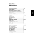
Following screen shopuld appear:
RSP command section
Virtual scope
Trigger level
(sensitivity)
Signal level
backward frequency (speed)
forward frequency (speed)
Virtual speed chart
backward speed
forward speed
Fig. 3: Initial RSP_Scope screen showing noise (top) and movement history (bottom)
Virtual scope (upper screen) has logarithmic Y-axis showing signal level. Therefore, noise looks
very high. Refer to the RSP datasheet for more explanations.
© 2014 RFbeam Microwave GmbH www.rfbeam.ch
Page 9/18
RSP1 Evaluation Kit
Preliminary User Manual
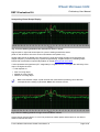
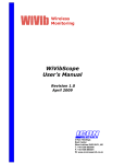
Interpreting Virtual Scope Display
Fig. 4: Person walking towards a two channel I/Q "stereo" sensor
Highest peak on right side shows speed of a person walking towards the sensor.
(Peak on the left side is due to the sensor I/Q inbalance and phase error)
Speed scale (X-axis) is related to the 256 point FFT signal processing algorithm and represents the
doppler frequency. Positive frequency represents approaching, negative frequency receeding object.
Please find more details on speed interpretation in chapter Background Information.
Y-axis represents the signal level (FFT magnitude) in a logarithmic form. The higher the reflectivity of the
object, the higher the level.
→ Level depends on:
Size of moving object
Material of moving object
Distance of moving object
RSP1 sets detection output, if peak exceeds the red threshold (sensitivity) and if direction
corresponds th the setting of parameter A05 or DIP-switches 3 and 4.
Fig. 5: Person walking towards a single channel "mono" sensor
Single channel sensors like K-LC1 or K-LC3 produce two similar peaks and therefore do not allow to
detect movement directions.
© 2014 RFbeam Microwave GmbH www.rfbeam.ch
Page 10/18
RSP1 Evaluation Kit
Preliminary User Manual
Horiztontal cursors may be activated on order to measure signal to noise ratio in dB.
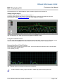
Adding IQ Signal Display
I/Q signal display appears at Channel switch position 4.
IQ display display directly the sensor's output signals that are captured by the RSP AD converter.
Please refer to chapter Doppler Signal Basics for more details on IQ signals.
Fig. 6: Frequency and Time signal of moving person towards sensor
Using the Command Feature
You may read and set parameters in the command section while RSP_Scope is running. Example: check
influence of parameter $A02 on the red theshold level. Use same syntax as for RSP_Terminal.
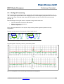
Interpreting Speed Chart Display
Chart displays object speed as a function of time. If IQ sensors are used, direction can be discriminated.
X-axis: Time (256* sampling time)
Y-axis: Speed (FFT bin)
Fig. 7: Speed of person moving forwards and backwards
In future versions of RSP_Scope, Axis will be scaled in physical time and speed units.
© 2014 RFbeam Microwave GmbH www.rfbeam.ch
Page 11/18
RSP1 Evaluation Kit
Preliminary User Manual
RSP1_Eval-Kit Hardware
Complete schematics are provided with the Evaluation Kit.
Additional information can be found in the RSP1 chip data sheet.
Power Supply
Stable and low noise power supply is essential for optimal sensor results.
For details, please refer to the Evaluation Kit circuit schematics and to the RSP1 data sheet.
RSP1_Eval-Kit may be powered bay different sources. Most convenient way is using the USB 5V power
from Personal Computer. USB power is very noisy. The evaluation kit uses a switched step-up regulator,
followed by a linear power supply resulting in a very clean power supply.
Eval-Kit provides 3 independent and decoupled power inputs:
- 5V USB power at X7a
- 5V USB power at X7b
- 6 .. 12VDC external supply at X4 and X5
Fig. 8: Evaluation Kit low noise supply concept
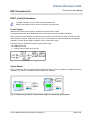
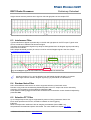
Digital Output
RSP1_Eval-Kit provides an optically isolated digital output with a maximum 28VDC, nominal 20mA driving
capability. The output is completely floating for maximum flexibility.
Fig. 9: Output wiring examples using external supply for output and system power
© 2014 RFbeam Microwave GmbH www.rfbeam.ch
Page 12/18
RSP1 Evaluation Kit
Preliminary User Manual
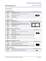
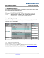
Connector Pins
X1 K-LCx connector
Pin
Signal
Description
1
IF Q
Doppler Signal (“Quadrature”)
2
Vcc
Sensor Power 5V or 3.3V, depending on Jumper J1 position
3
IF I
Doppler Signal (“In Phase”)
4
GND
Sensor Ground
5
VCO
FM output, not used
Connector top view
1
X2 K-LCx connector
Located on backside of the Eval-Kit
Pin
Signal
Description
1
IF Q
Doppler Signal (“Quadrature”)
2
Vcc
Sensor Power 5V or 3.3V, depending on Jumper J1 position
3
IF I
Doppler Signal (“In Phase”)
4
GND
Sensor Ground
5
VCO
FM output, not used
Sensor mount on PCB backside
1
X3 K-MCx connector (alternate sensor)
Pin
Signal
Description
1
GND
Sensor /enable
2
Vcc
Sensor Power 5V or 3.3V, depending on Jumper J1 position
3
GND
Sensor Ground
4
IF Q
Doppler Signal (“Quadrature”)
5
IF I
Doppler Signal (“In Phase”)
6
VCO
Not connected
7
IF Q DC
Not connected
8
IF I DC
Not connected
Connector top view
2
8
1
7
X4 Digital output and power connector
Pin
Signal
Description
1
+DC
+6 .. 12V power supply input (in parallel to X5 center pin)
2
+DOUT
Opto isolated detection out plus side
3
-DOUT
Opto isolated detection out minus side
4
GND
Ground power supply input (in parallel to X5 outer contact)
Connector top view
1
X5 power supply input
Pin
Signal
Description
1
+DC
+6 .. 12V power supply input (in parallel to X4 pin 1)
2
GND
Ground power supply input (in parallel to X4 pin 4)
© 2014 RFbeam Microwave GmbH www.rfbeam.ch
Connector top view
+
-
Page 13/18
Preliminary User Manual
RSP1 Evaluation Kit
X6 Digital I/O and SPI
Pin
Signal
Description
Connector top view
1
NC
2
GND
3
NC
4
Detect out
digital processor output: high at detection + hold time
5
MISO
SPI Master-In-Slave-Out
6
CMD Tx Enable
Enable signal for RS-485 drivers
7
SCK
SPI Serial clock
8
MOSI
SPI Master-Out-Slave-In
9
nSS
SPI slave select
10
GND
Signal Ground
Signal Ground
2
10
1
9
Grey signals: reserved for future implementation
X7a Serial Command Interface
Outer row of X7: 38400Baud 3.3V command interface.
FTDI compatible pin layout.
Pin
Signal
Description
1
GND
Power GND
2
NC
Not connected
3
+5V
Power supply input
4
RXD
serial UARTdata input
5
TXD
serial UART data output
6
NC
Not connected
Connector top view
FTDI cable black wire
1
X7b Serial Debug Interface
1Inner row of X7: 38400Baud 3.3V command interface
FTDI compatible pin layout.
Pin
Signal
Description
1
GND
Power GND
2
NC
Not connected
3
+5V
Power supply input
4
RXD
serial UARTdata input
5
TXD
serial UART data output
6
NC
Not connected
Connector top view
FTDI cable black wire
1
Serial Debug Interface is also used for updating RSP1 firmware
© 2014 RFbeam Microwave GmbH www.rfbeam.ch
Page 14/18
Preliminary User Manual
RSP1 Evaluation Kit
Background Information
Doppler Signal Basics
A moving object in range of a Radar sensor (often called “transceiver “) generates a low frequency output
signal. Frequency depends on the object speed. Amplitude depends on distance, reflectivity and size of
the object. Doppler frequency fd is proportional to the object speed v:
α
fd
44 Hz
km / h
f d =v⋅
⋅cos α v=
44 Hz⋅cos α
km / h
moving
object
Radar sensor
Note that the angle of the moving object reduces Doppler frequency.
I/Q Doppler Signals
I/Q sensors like K-LC2, K-LC5, K-LC6 and others produce 2 output signals, that are phase shifted by 90°.
Main advantages:
Forward / Backward movement differentiation
Efficient interference suppression
Vibration suppression
Fig. 10: I/Q signals left: approaching; right receding movement
FFT Fast Fourier Transform
Explanations go beyond the scope of this document. Please refer to literature (e.g.
http://en.wikipedia.org/wiki/Fast_Fourier_transform and to the RSP1 datasheet.
Fortunately, RSP1, the user does not have to care about the details on FFT.
FFT represents in fact many narrowband filters that reduce noise amplitude. RSP1 uses 256 point FFT
resulting in 128 bins (filters) for each forward and backward movements.
This kind of detection results in a much better sensitivity than simple comparator solutions. Theoretical
gain in S/N ratio by using a 256pt (2 8) FFT is 10 * log(8) = 24dB. In reality, more than double detection
distances can be reached compared to comparator solution.
RSP1 debug port and RSP_Scope help understanding using FFT in movement and speed sensors.
© 2014 RFbeam Microwave GmbH www.rfbeam.ch
Page 15/18
Preliminary User Manual
RSP1 Evaluation Kit
Sampling Rate and Bandwidth
Chosing optimal sampling rate is crucial for best detection results.
There are close relationships and dependencies between
•
•
•
•
•
•
size of FFT (RSP1 uses 256pt Fast Fourier Transform)
sampling rate
detectable speed range
speed resolution
amplifier bandwidth
system sensitivity (signal to noise ratio SNR)
Minimum Sampling Rate
Sampling rate fs must be at least twice the highest Doppler frequency appearing in the application.
f s >2⋅f d (Nyquist criteria)
However, the higher the sampling rate, the lower the frequency resolution:
d f >FFTn /f s
(In RSP1: FFTn = 256)
Maximum Amplifier Bandwidth
Amplifier bandwidth must be significantly lower than the maximum frequency mentioned in Fig. 11.
2nd order lowpass filter is recommended. Otherwise, aliasing effects will occur. ( Wikipedia
http://en.wikipedia.org/wiki/Nyquist%E2%80%93Shannon_sampling_theorem).
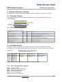
Sampling Rate Table
Sampling rate can be set by parameter S03.
Parameter
S03
sample rate
Hz
resolution
Hz
max. frequency
Hz
resolution
km/h
max speed
km/h
response time
ms 1)
01
1'280
5
640
0.11
14.5
200
02
2'560
10
1'280
0.23
29.1
100
03
3'840
15
1920
0.34
43.6
67
04
5'120
20
2''560
0.45
58.2
50
05
6'400
25
3'200
0.57
72.7
40
06
7'680
30
3'840
0.68
87.3
33
07
8'960
35
4'480
0.80
101.8
29
08
10'240
40
5'120
0.91
116.4
25
09
11'264
44
5'632
1.00
128.0
23
0A
22'530
88
11'265
2.00
256.0
12
Note 1): response time on host interface. Digital output depends also on params $A03 and $S02
Fig. 11: Detectable speed depend on parameter S03
© 2014 RFbeam Microwave GmbH www.rfbeam.ch
Page 16/18
RSP1 Evaluation Kit
Preliminary User Manual
Rule of Thumb for your application:
Use lowest possible amplifier bandwidth at highest possible sampling rate
Using Serial Interfaces in parallel
RSP_Scope connected to Debug Interface X7b) and RSP_Terminal (connected to Command Interface
X7a) may be used in parallel. A 2nd FTDI cable is required for this.
This RSP1 feature becomes important for debugging applications with a host CPU connected to the RSP1
Command Interface with the RSP_Scope connected to the debug port.
General Radar Installation Tips
Radar for movement detection is a very reliable and robust technology. It is insensitive to heat, wind, dust,
sunlight and other influences.
However, there are some important issues to take into consideration:
Sensitivity to fluorescent light (→ use IQ modules and/or RSP1 FFT Filter features)
Material and thickness of cover
Sensitivity to vibrations (→ use I/Q modules)
The following application notes should help to optimize your application.
Cover
Every cover has some influence on the shape of detection field and the achievable maximum distance.
Radar can „view“ through plastic and glass of any color. This makes a high degree of design freedom.
Nevertheless, some rules should be considered.
Cover must not be metallic.
Plastic coating with colors NOT containing metallic or carbon particles.
Distance between cover and front of Radar sensor > 1cm
Best cover material is Polycarbonat or ABS
Best cover thickness is 3-4mm
Vibrations of sensor module relatively to the cover should be avoided, because this
generates signals that can trigger the output
Interference Factors
RSP1 designs are much more robust against interference factors than traditional Radar based designs.
Nevertheless, take care on the following tips.
Fluorescence Light
Do not mount Radar modules directly facing to fluorescent lamps
Use sensors at the lowest possible sensitivity for your certain application
Radar is susceptible to fluorescent lamps, even if controlled by electronic ballasts. These lamps produce a
100Hz (50Hz mains, Europe) or 120Hz (60Hz mains, USA) Radar signal that is similar to the signals
produced by a person walking at about 2km/h.
RSP1 features adaptive filters, intelligent suppression algorithms and selective programmable FFT filters.
Refer to RSP1 datasheet.
© 2014 RFbeam Microwave GmbH www.rfbeam.ch
Page 17/18
Preliminary User Manual
RSP1 Evaluation Kit
Rain
Prevent cover to get wet
The lager the distance to rainy environment, the smaller the rain effect.
Raindrops can be interpreted by Radar as moving objects and may trigger the output.
Vibrations, Ventilators etc.
Radar based sensor and its cover should be mounted stable to prevent vibrations
Try to prevent objects like ventilators in the sight of the detection field
Sensitivity and Maximum Range
Sensitivity defines the necessary signal strength at the Radar sensor to trigger the output.
RSP1 allows adjusting sensitivity by potentiometer and/or by parameters.
Trigger distance at same sensitivity setting can vary depending on
Type of moving object (person, car etc.).
Moving direction of the object
Further Reading
RSP1 datasheet contains important information on signal processing and hardware design.
Schematics of the RSP1 Evaluation Kit are included on the installation media.
Application note AN-04 contains amplifier examples.
http://www.rfbeam.ch/fileadmin/downloads/appnotes/AN-04%20TypicalSignalAmp.pdf
Application Note AN-03 contains tips for cover ("Radome") and housings
http://www.rfbeam.ch/fileadmin/downloads/appnotes/AN-03-Radome.pdf
Revision History
Version 0.2
Version 0.3
Sept 21, 2014
Nov 01, 2014
Preliminary release
Preliminary release
RFbeam does not assume any responsibility for use of any circuitry described, no circuit patent licenses are implied and
RFbeam reserves the right at any time without notice to change said circuitry and specifications.
© 2014 RFbeam Microwave GmbH www.rfbeam.ch
Page 18/18
RFbeam Microwave GmbH
RSP1 Radar Processor
Preliminary Datasheet
Features
Universal Doppler Radar signal processor
Complete I/Q Radar sensor interface
Complex FFT based signal processing
Double detection distance compared to traditional solutions
Object speed and direction detection up to 250km/h
Efficient adaptive interference suppression
Stand-alone or hosted operation
Evaluation Kit available
1 Applications
Movement detectors
Lighting control systems
Security applications
Object speed detection
2 Description
2.1 Application Example
RSP1 contains all Doppler signal processing.
Up to now, development of Doppler Radar signal processing has been a time consuming matter and
needed experience in analog and digital electronics.
With RSP1, typical applications need minimal external components. Configuration can be made by
switches and potentiometers or fully digital via serial interface.
Linear power regulators
3.3V
RFbeam RSP1
I
detect out
Radar
inputs
Q
LED detection
optional
K-LCx Radar Sensor
5V or 3.3V
LED busy
sensitivity
hold time
serial interface
sensor type
directional
fwd / bwd
immunity
serial debug
Fig. 1: Typical stand-alone application circuitry
© RFbeam Microwave GmbH www.rfbeam.ch
1/25
RFbeam Microwave GmbH
RSP1 Radar Processor
Preliminary Datasheet
2.2 RSPx Family
RSP1 is the first member of RFbeam Radar signal processors.
The RSPx family helps users concentrating on their application know-how instead of investing time and
money in raw signal processing.
RSP1 contains all signal processing for Doppler Radar. It covers slow movement detectors as well as
speed estimators up 250km/h.
It can be used as stand alone processor or as a co-processor in higher complexity systems.
User has only to add an input amplifier and digital output drivers and gets a high performance detection
system.
Evaluation and development is supported by the RSP1 Evaluation Kit reference design.
2.3 Key Data
12 Bit ADC
Differential analog inputs for I and Q signals
Internal programmable gain amplifier
Sampling rates from 1280Hz to 22.5kHz
Efficient 256pt complex FFT
Logarithmic detection algorithms
Adaptive noise and interference analysis and canceling algorithms
Serial command and debug/streaming interfaces
Commands include peak magnitude, frequency and sign, noise level and many more
Highly configurable by serial interface and/or digital and analog inputs
Application settings can be down- and uploaded from chip
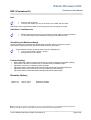
2.4 RSP1 Evaluation Kit
RSP1_Eval-Kit; Left: K-LC2 sensor on front connector; Right: Backside equipped with K-LC6 sensor
With RSP1 Evaluation Kit, you may explore most features of RSP1 working with different RFbeam
sensors. 5 different sensors are included in the kit.
Using a RSP_Terminal you have access to more than 30 parameters. Explore FFT, noise and other
signals with the RFbeam SerialScope PC Software, that.also makes part of the kit.
All schematics, PCB layout and BOM are included as a reference.
© RFbeam Microwave GmbH www.rfbeam.ch
2/25
RFbeam Microwave GmbH
RSP1 Radar Processor
Preliminary Datasheet
3 Sensor Configurations
RSP1 Chip may be used with one or two sensors. Sensors can not be used in parallel, but as alternative
sensor connected to the Alt_RADAR inputs. Inputs can be selected by parameter S01.
Channels
Sensor examples
Comments
1 ("mono")
K-LC1a, K-LC3
Lowest cost. Mostly used for indoor applications
2 ("stereo")
K-LC2, K-LC5, K-LC6, K-MC1
Directional detection, excellent interference suppression
Table 1: Sensor Configurations
3.1 Single channel vs Dual channel (I/Q) processing
RSP1 can be operated with dual channel ("stereo") I/Q sensors as well as with one channel ("mono")
sensors (see Table 1: Sensor Configurations).
Feature
Dual channel
Directional detection (receeding / approaching)
x
Interference suppressin (fluorescence lights, vibrations and others)
x
Noise suppression (better sensitivity)
x
Lower cost
Single channel
x
Table 2: Dual channel versus single channel comparison
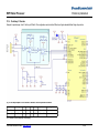
Sensitivity Direction Hold Time
+
-
I
K-LCx
Radar Sensor
ADC
Q
digital
FFT
serial
ADC
debug
RSP1
Amp
Output
Fig. 2: Typical dual channel architecture
Hold Time
Sensitivity
K-LCx single
channel
Radar Sensor
I
ADC
FFT
ADC
Amp
digital
serial
debug
RSP1
Output
Fig. 3: Typical single channel architecture
© RFbeam Microwave GmbH www.rfbeam.ch
3/25
RFbeam Microwave GmbH
RSP1 Radar Processor
Preliminary Datasheet
4 RSP1 Architecture
4.1 Data Acquisition
An internal, programmable differential amplifier allows gains from 1 to 16.
RSP1 works with 2 12Bit ADCs, sampling rate is selectable between 1'200Hz up to 22.5kHz in 10 steps.
This corresponds to maximum speeds from 13km/h to 250km/h.
4.2 Data Processing
Processing is based on a complex FFT and on an adaptive noise threshold. Many parameters allow
adjusting and optimizing the performance for many different applications.
Advantages of FFT
FFT stands for Fast Fourier Transform, that allows signal processing in the frequency domain (see
details on http://en.wikipedia.org/wiki/Fft).
Processing of the Quadrature Doppler signals is performed by a complex FFT. Using FFT results in much
better performance than using simple comparator designs or time domain processing.
The RSP1 FFT implementation leads to sophisticated movement and speed detectors:
•
•
•
•
•
•
Better S/N (21dB with 256pt FFT) → 2 to 3 times larger detection range
Inherent object speed detection
Reliable distiction between approaching / receding objects
Efficient interference suppression through complex FFT (fluorescent light, rain, vibrations …)
Narrowband filtering of known interference frequencies
Selective and adaptive noise threshold capability
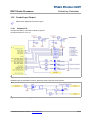
RSP1 Hardware Architecture
The processor architecture allows data acquisition and processing in parallel. Only a few external
components are needed thanks to the high integration level including EEPROM and precision clock
generator.
Timer & Event System
Sensor I
Ref In
Sensor Q
Hold Pot
Sens. Pot
12 Bit
ADC
DMA
RAM
CPU
ADC
ADC
I/O
digital
FFT
A = 1 .. 16
analog
serial
Flash
5 x Out
4 x In
VCO
Control
Debug
EEPROM
Fig. 4: RSP1 simplified block diagram
© RFbeam Microwave GmbH www.rfbeam.ch
4/25
RFbeam Microwave GmbH
RSP1 Radar Processor
Preliminary Datasheet
5 Performance data
5.1 Overview
RSP1 is working at an internal clock frequency of 32MHz.
Radar I and Q signals pass a programmable gain amplifier (A=1 to 16). A 12Bit differential ADC running
at a 500kHz clock converts the amplified signals. I and Q channels are acquired quasi parallel with a time
shift of 2us.
Complex 256pt fixpoint FFT runs in parallel to the data aqcuisition. Time signal passes a Hanning
window and is then processed by the FFT.
Acquisition is interrupted only by a 300us windowing calculation time. All other signal processing is
performed in parallel to the data acquisition.
5.2 Internal Timing
Sampling timing depends on setting of parameter S03 (sampling rate). This results in following FFT
resolutions and measuring speed ranges:
Parameter S03 (hex)
fs (sampling freq.)
df (resolution)
max. speed
remark
01 … 08
S03 value * 1280Hz
5Hz to 40Hz
4.5km/h to 116km/h
allows direct readout of frequency
09
11.254kHz
44Hz (1km/h)
127km/h
allows direct readout of speed in km/h
0A
22.528kHz
88Hz (2km/h)
255km/h
allows direct readout of half speed
tacq
Sampling
Processing
3
1
2
3
t1
t2
t3
1
2
3
1
2
Fig. 5: Acquiring and processing executes in parallel. A small gap (t3) occurs during windowing
tacq
t1
t2
t3
= 256 * 1/fs = 11.4ms … 200ms (with fs = 22.5kHz … 1280kHz)
= 7.7ms
FFT
= 2ms
Logarithmic result conversion
= 0.3ms
Hanning window calculation
ADC Sampling of both channels is performed quasi-parallel with a maximum time shift of 2us max.
5.3 Response time
Response time on parameter requests on sampling rate fs (parameter S03):
tRmin
= 11.4ms * A03 value (S03 = 0A)
tRmax
= 200ms * A03 value
(S03 = 01)
Update time on result parameters and digital outputs depend on sampling rate fs (parameter S03), on
and immunity value (parameter A03) and on FFT avaraging (parameter S02).
tUPDmin = 11.4ms * A03 value (S03 = 0A, S02 = 00) or 22.8ms * A03 value (S02 = 01)
tUPDmax = 200ms * A03 value
(S03 = 01, S02 = 00)
or 400ms * A03 value (S02 = 01)
See also chapter 8.4 Sampling Rate and Frequency Resolution
© RFbeam Microwave GmbH www.rfbeam.ch
5/25
RFbeam Microwave GmbH
RSP1 Radar Processor
Preliminary Datasheet
5.4 Internal signal representation
RSP1 computes the complex amplitude spectrum of the input I/Q signals.
Analog conversion is performed with 12Bit resolution. In order to get better accuracy in fixpoint
calculations, ADC result is left shifted by 4 bits resulting in a value range from -32'768 … 32'767.
All internal processing and signal parameter settings are based on logarithmic FFT results.
This allows optimal handling of small signals and fits well to the Radar signal vs. object distance
behaviour.
Step
Processing stage
Value range
Remark
1
Input signal (Radar Common input = 1.65V)
3.3Vpp (A=1) .. 206mVpp (A=16)
resolution 806µV/bit @A=1
2
Internal amplification
A = 1, 2, 4, 8, 16
Parameter S09
3
AD conversion 12 bit signed
-2048 … + 2047
2 channels in parallel
4
Internal representation * 16
-32768 … + 32767
used to enhance FFT accuracy
5
16/32 bit fix point FFT with Hamming window
magnitude 0 … 23'168
6
log conversion in fixpoint form x.yy
log10 as integer: 0 … 437
corresponds to 0 … 4.37
Table 3: Internal processing stages
Value
Range / conversion
Remark
Input voltage at Radar input
1.65Vp = 1.17Vrms
Gain A = 1; parameter S09= 0
Input voltage at Radar input
193mVp = 72.9mVrms
Gain A = 16; parameter S09 = 4
Maximal internal signal level
437
logarithmic magnitude level * 100
Internal signal level relation to dB
dB ≙ value / 5
Internal FFT magnitude at 1Vrms input [dBVrms] = value - 86
430 / 5 = 86
Max. input frequency
640Hz .. 11.25kHz
sampling rate / 2 (see parameter S03)
Frequency resolution
sampling rate / 256
5Hz ... 88Hz
Speed resolution
0.1km/h ... 2km/h
corresponds to 5Hz to 88Hz
Table 4: Useful signal level conversions
© RFbeam Microwave GmbH www.rfbeam.ch
6/25
RFbeam Microwave GmbH
RSP1 Radar Processor
Preliminary Datasheet
6 Detection Algorithm
Detection algorithms are based on the complex FFT (Fast Fourier Transform) of the I and Q analog
signal inputs.FFT output logarithmic in order to get good signal processing conditions for both large and
small signals.
FFT represents in fact many narrowband filters that reduce noise amplitude. RSP1 uses 256 point FFT
resulting in 128 bins (filters) for each forward and backward movements.
This kind of detection results in a much better sensitivity than simple comparator solutions.
Approximative gain in S/N ratio by using a 256pt FFT is 10 * log(128) = 21dB. In reality, more than
double detection range can be reached compared to comparator solution.
Signals and processing behaviour may be explored by the RFbeam tool RSP1_Scope,
connected at the serial debug port (see 7.5 Serial Debug Interface)
6.1 Adaptive noise detection
The advanced noise detection technique leads to the outstanding sensitivity of the RSP1 solution.
Noise is measured separately for each frequency represented by the FFT results. Two stages in noise
measurement exist:
1. After power-on, an initial noise curve is built by measuring the mean of each FFT frequency bin.
Number of means (measuring time) can be selected by Parameter S04.
2. Adaptive mean is continuously built during operation. Adaptation time constant ca nbe selected by
Parameter S0C
If using I/Q stereo sensors (like K-LC2, K-LC5 etc.), noise cancellation is very efficient, because
movement Doppler signals can be efficiently distinguished from noise signals.
backward
forward
interference
I/Q signal
interference
Trig level
noise
mean
FFT
Fig. 6: Signal levels used for object detection. Example: forward moving object
Trigger level results from the sum of adaptive noise
threshold (Grey plot) and the sensitivity selected by
parameter A02.
Signal in the center is the DC offset caused by the
amplifier and ADC converter.
signal level
Trigger threshold
sensitivity (param A01)
min.trigger margin (param S0A)
noise level
Noise and small signals looks very strong in logarithmic form of the FFT magnitude. Remember
that a signal difference of 1mVrms to 2mVrms produces same logarithmic magnitude difference
as a difference from 500mVrms to 1Vrms.
© RFbeam Microwave GmbH www.rfbeam.ch
7/25
RFbeam Microwave GmbH
RSP1 Radar Processor
Preliminary Datasheet
6.2 I/Q Signal Processing
RSP1 supports I/Q processing by using complex FFT. I/Q Doppler signals are phase shifted by + 90° or
-90°. Those signals appear either in the real(right) plane or in the imaginary (left) plane of the FFT output.
Signal in the center is the DC offset caused by the amplifier and ADC converter and can be ignored.
(see Fig. 8).
Main advantages of using I/Q sensors compared to single channel sensors:
•
•
•
Forward / Backward movement differentiation
Efficient interference suppression
Vibration suppression
Even if directional detection is not required, I/Q processing allows significantly better immunity
suppression.
Doppler I and Q signals in Time domain at RSP1 Radar inputs:
I signal
Q signal
Q signal
I signal
Fig. 7: I/Q signals left: approaching; right receding movement
Doppler signals in Frequency domain, processed by RSP1:
Fig. 8: FFT magnitude of forward moving and backward moving objects
© RFbeam Microwave GmbH www.rfbeam.ch
8/25
RFbeam Microwave GmbH
RSP1 Radar Processor
Preliminary Datasheet
Single channel sensors produce same signal on left and right plane of the complex FFT.
Fig. 9: Single channel signal appears symmetrically in the left and right half
6.3 Interference Filter
Typical interferences appear symmetrically on the left and right plane in the FFT output. Typical noise
source are electronic ballasts and fluorescent lights.
Therefore those interference signals may easily be distinguished from I/Q Doppler signals produced by
stereo sensor modules:
RSP1 adapts threshold (red line) for noise, but not for real I/Q Doppler signals. See also chapter
6.1 Adaptive noise detection
I/Q Doppler signal
interference
Fig. 10: I/Q Doppler signal at +44; interference produces 2 peaks on 100 and -100
Interferences like in Fig. 10 look different from I/Q Doppler signals caused by movement.
With single channel modules, Doppler signals (Fig. 9) look similar to interferences.
6.4 Random Noise Filter
RSP1 offers different mechanisms in order to suppress influence of stochastic noise:
Random noise produces stochastically distributed peaks in the FFT output and can be reduced by
averaging. FFT averaging can be enabled by parameter S02.
Noise peaks exceeding trigger threshold are counted and must exceed a counter threshold adjusted by
parameter A03.
6.5 Selective FFT Filter
Up to 8 single frequencies may be suppressed by means of array parameters X20 to X27.
Each value represents an FFT bin, that will be masked out from triggering.
Example:
Mask out frequencies 100Hz and 1kHz at sampling rate 2560Hz (Param S02 = 02).
Set parameter X20=000A and param X21=03E8. For more details see chapter FFT Filter
© RFbeam Microwave GmbH www.rfbeam.ch
9/25
RFbeam Microwave GmbH
RSP1 Radar Processor
Preliminary Datasheet
7 Interfaces
RSP1 provides different interfaces for configuration and control signals. RSP1 can be used as a standalone processor or in conjunction with a host controller.
• Command interface:
Standard UART interface for parameter settings with 38'400Baud.
• Debug Interface:
High speed UART interface for debug purposes with 460'800Baud
(Parameter S06).
This interface acts also as bootloader interface for software updates.
• Digital I/O:
Control signals for status LED, digital outputs and optional SPI interface.
7.1 Analog I/O
Please refer to chapter 13 Sample Schematics for details of analog signal handling.
Range of RADAR input signals depend on the internal gain setting by parameter S09:
S09 = 0: range 3.3Vpp; S09 = 4: 200mVpp.
Pin
Function
Remark
AVcc
Power supply for chip analog section
Decouple well: see Fig. 14
RADAR_AREF
ADC reference voltage
Vcc/2 (1.65V), connect to RADAR_COMMON
RADAR_COMMON
Input reference voltage
Vcc/2 /1.65V) decoupling see Fig. 14
RADAR_I1
Radar in-phase signal (I)
Signal referenced to RADAR_COMMON
RADAR_Q1
Radar in-phase signal (Q)
Signal referenced to RADAR_COMMON
ALT_RADAR_I1
Alternative Radar I input
selected by parameter S01
ALT_RADAR_Q1
Alternative Radar I input
selected by parameter S01
ALT_RADAR_COMMON
Input reference voltage
connect to RADAR_COMMON
HOLD_POT
Optional hold time setting
Range 0 to Vcc/2. Function must be enabled by param. S07
SENS_POT
Optional sensitivity setting
Range 0 to Vcc/2. Function must be enabled by param. S06
7.2 Digital I/O
All digital inputs have internal pull-down resistors and are high active.
Secondary pin functions (IDx) are reserved for future versions.
7.2.1 Mode settings
- Input SETTING_MODE must be tied to Vcc in order to activate the setting inputs.
- Setting inputs are sampled at power ON only
- Settings can be over-written by sending similar software parameter commands
Pin
Function, if high (3.3V)
Remark
SENSOR_MONO
1 channel sensor connected
e.g. K-LC1a, K-LC3
DIR_MONO
no directional processing
detect both movement directions with I/Q sensors also
DIR_BACKWARD
detect receding movements only
DIR_MONO input must be low / left open
IMMUNITY
set extended interference immunity
SETTING_MODE
enable setting inputs
© RFbeam Microwave GmbH www.rfbeam.ch
if low or left open, setting inputs have no effect
10/25
RFbeam Microwave GmbH
RSP1 Radar Processor
Preliminary Datasheet
7.2.2 Control Outputs
Digital outputs are high active push-pull circuits with typically 10mA driving power.
Pin
Function, if high (3.3V)
Remark
LED_BUSY
RSP is busy and is not detecting
Active during power-on learning
LED_DETECT
Active, as long as movement is detected
including hold time
DETECT_OUT
same signal as LED_DETECT
use for driving external hardware output
LOW_BANDWIDTH
set according to parameter S08
optional use for external amp bandwidth limitation
CMD_TX_ENABLE
reserved for future RS-485 expansion
active during serial transmission
CMD_TX
Command interface UART Tx
see chapter 7.3 Host Command Interface
CMD_RX
Command interface UART Rx
see chapter 7.3 Host Command Interface
DETECT_SIGNAL
same signal as DETECT_OUT
optional use for digital signaling to host device
7.3 Host Command Interface
This is a 3.3V asynchronous UART interface:
Pins:
Input: CMD_RX, output CMD_TX
Physical data: 38'400Baud, 8 databit, 1 stopbit, no parity, no handshake
Protocol:
Client-Server protocol. RSP1 acts as server. See 8 Software Parameter Settings
This interface is supported by the RSP_Terminal tool.
7.4 SPI / IO Interface
This interface is reserved for future versions of RSP1.
© RFbeam Microwave GmbH www.rfbeam.ch
11/25
RFbeam Microwave GmbH
RSP1 Radar Processor
Preliminary Datasheet
7.5 Serial Debug Interface
Debug interface provides highspeed parameter access as well as streaming output of I and Q signals
and FFT results signals over a serial UART interface.
This is a 3.3V asynchronous UART interface:
Pins:
Input: DEBUG_RX, output DEBUG TX
Physical data: 460'800Baud (parameter S0B), 8 databit, 1 stopbit, no parity, no handshake.
Protocols:
- Streaming protocol,
supported by RSP_Scope tool. (see chapters below)
- Client-server protocol supported by RSP_Scope and RSP_Terminal tool
- Bootloader protocol. Proprietary, for use with RSP_PROG tool
7.5.1 Cyclic Signal Streaming
Cyclic signal streaming is a continuous data stream with no host intervention except start and stop.
This mode is initiated by commands D0001 and D0002 the Host Command Interface .
RSP1 then outputs cyclic binary data frames on Debug Interface.
Cyclic output stops at command D000.
Protocol Item
Binary data items on line DEBUG_TX
Format
Sync Header
0x24, 0x02, 0xa2, 0xe1, 0x5a, 0xd6, 0x19
7 Bytes
Mode Byte
0x7a or 0x0F
1 Byte
FFT bin -128
High, Low Byte
Threshold bin -128
High, Low Byte
I signal sample 0
High, Low Byte
Q signal sample 0
High, Low Byte
Comment
D00x1 or D00x2
Only at commands
D0002 or D0012
….
1024 or 2048 bytes
for "Scope" display
FFT bin 127 High Byte, Low Byte
Threshold bin 127 High Byte, Low Byte
I signal sample 255
High Byte, Low Byte
Q signal sample 255
High Byte, Low Byte
Only at commands
D0002 or D0012
High Byte, Low Byte
High Byte, Low Byte
2 data bytes
strongest object
speeds
Forward frequency peak index 0 to 127
1 Byte
0: no peak, >0 speed
Backward frequency peak index 0 to 127
1 Byte
0: no peak, >0 speed
Table 5: Debug cyclic and single shot protocol
7.5.2 Single Shot Signal Streaming
Single shot streaming is a client server protocol.
This mode is initiated by commands D0011 and D0012 at the Debug or Host Command Interface.
RSP1 then outputs one binary data frame on Debug Interface.
Data frame is the same as in the cyclic protocol described before in 7.5.1 Cyclic Signal Streaming
© RFbeam Microwave GmbH www.rfbeam.ch
12/25
RFbeam Microwave GmbH
RSP1 Radar Processor
Preliminary Datasheet
8 Software Parameter Settings
Parameters may be set by the command interface. It works at 38.4kBaud, 1 stop bit and no parity.
8.1 Parameter Storage
All parameters except real-time and debug parameters are permanently stored into the processorinternal EEPROM.
Factory Default Parameters
Set by serial
command
- first run
- on request
User Parameters
Fig. 11: EEPROM parameter organization
Parameters are divided into classes:
Parameter Type
Par.
Class
EEPROM
Purpose
Application parameters
A
Yes
End-User specific settings in final application
System parameters
S
Yes
Application specific parameters
Array parameters
X
Yes
Application specific tables
Real time read parameters
R
No
Real-Time information on processing state
Real time write parameters
W
No
Real-Time commands
Debug parameters
D
No
Debug behavior control
Table 6: Setting parameter types and classes
8.2 Parameter Format
Parameter changes (except class W and D) will be directly stored into the EEPROM user space.
Parameters are set by a serial UART interface and may be set by a host CPU or by an ASCII terminal:
aa
P nn
vv
<CR>
Example request
RSP response
Comment
Parameter class
Value (Hex)
“Enter”
$A02<CR>
$A0207<CR>
@A0209<CR><LF>
@A0207<CR><LF>
Actual value request
Set new value
Number(Hex)
$
Prefix
38.4KBaud, 8 bit data, 1 stop-bit, no parity ("8n1")
Request with prefix $; answers come with @ prefix
<CR> represents Enter key (0x0D hex)
Optional Node ID
Physical format:
Format:
Table 7: Setting parameter format (Node ID is reserved for future RSP1 derivatives)
8.2.1 Error messages (RSP response)
@E01: value out of limits
@E02: parameter number does not exist
@E03: parameter class does not exist
@E04: writing to EEPROM error
@E05: command format error
@E06: UART communication error
© RFbeam Microwave GmbH www.rfbeam.ch
13/25
RFbeam Microwave GmbH
RSP1 Radar Processor
Preliminary Datasheet
8.3 Parameter List
8.3.1 8 Bit Parameters
All values are in hexadecimal notation! Except values marked with *. Column "R": needs reset
Param.
default min max Function
Description
Class A
(EEPROM)
Application Parameters
End-User specific settings in final application
A00
00
00
00
reserved
reserved for future use
A01
01
00
09
hold time
9: maximum hold time of detection output
A02
09
00
09
sensitivity
9: maximum detection sensitivity
A03
03
00
09
immunity
9: maximum immunity against interference
A04
00
00
00
reserved
reserved for future use
A05
00
00
02
direction
0: approaching; 1: receding; 2: both
A06 … A0F
00
00
00
reserved
reserved for future use
Class S
(EEPROM)
System Parameters
Application specific parameters
S00
00
00
01
sensor type
0: stereo I/Q sensor; 1: mono sensor (1 channel)
x
S01
00
00
01
Use alternate analog port
1: ADC input on pin 2 and 3 instead of pin 44 and pin 1
x
S02
01
00
01
FFT average
1: averaging on
S03
02
01
0A
sampling rate
rate = value*1280Hz, except 9: 11.264kHz; A: 22.53kHz
x
S04
10
01
40
start up learn
noise learn cycles after reset
x
S05
01
01
02
active sensors
reserved
x
S06
01
00
01
sensitivity pot
1: use potentiometer for sensitivity setting
x
S07
01
00
01
hold time pot
1: use potentiometer for hold time setting
x
S08
01
00
01
bandwidth
1: low bandwidth (digital output used for external filter)
S09
04
00
04
ADC gain
gain = 2^n: 0 -->1; 1-->2; 2-->4; 3-->8; 4-->16
x
S0A
38
20
50
minimum trigger margin
minimum margin between noise and max. sensitivity
x
S0B
00
00
00
baudrate serial debug port
0:460800; 1:115200; 2: 38400
x
$S0C
00
00
FF
threshold adapt. speed
00:max. depending on sampling rate; >0: n*500ms / dB
S0D … S0F 00
00
00
reserved
reserved for future use
Real-Time Read Params
Read only parameters
Class R
(immediate)
R00
-
00
01
detection active?
1: detection output active (includes hold time)
R01
-
00
FF
detection speed
>0 peak position (FFT bin #)
0
FF
noise level mean
arithmetic mean over all FFT bins
R02
R03
-
00
02
operation state?
start up; learn; run
R04
-
00
FF
software version
major.minor version (x.0 are preliminary versions)
R10
*
--
--
software version string
Full software version and date string, max 40 characters
R11
*
--
--
result string
SpeedFW, SpeedBW, MagFW, MagBW<CR>
R20
*
--
--
get EEPROM hex string
Full 512 EEPROM bytes in Intel hex format
Class W
(immediate)
Real Time Write Params
Volatile write parameters
W00
-
00
01
force detection output
1: set digital detection output; 0: normal output operation
W01
-
-
-
reset processor
software reset. value has no effect
W02
-
-
-
load default parameters
load default values for all parameters
W03
00
00
01
reserved for future use
1: power saving and output disable.
W04
-
-
-
dump EEPROM content
get all permanent parameters
W0B
-
-
-
enter bootloader
switches to bootloader on serial debug port
© RFbeam Microwave GmbH www.rfbeam.ch
R
14/25
RFbeam Microwave GmbH
RSP1 Radar Processor
Preliminary Datasheet
Param.
default min max Function
Description
Class L
LOOP
Continuous Output
Streaming comma separated results
L00
-
Peak positions, Peak values
SpeedFW, SpeedBW, MagFW; MagBW<CR> (DECIMAL)
Start:$L00 or $L0001; Stop: $L0000 or other parameter
Class D
DEBUG
Debug stream
Control serial data stream loop at debug interface
D00
-
00
02
Cyclic FFT on DEBUG int.
1: 2 ch. (FFT + Threshold); 2: 4 ch: additional I and Q
D00
-
11
12
One shot FFT on DEBUG int.
11: 2 ch. (FFT + Threshold); 12: 4 ch: additional I and Q
00
01
R
Table 8: 8 Bit parameters overview
8.3.2 16 Bit Array Parameters
Purpose: Values indirectly accessed by simple 8 bit parameters.
These parameters represent arrays that are addressed by 8Bit parameters or by signal processing.
Values may be adapted and are application specific.
All values are in hexadecimal notation!
Param.
default min
Class X
(EEPROM)
X00...X09
*)
max
Function
Description
Array parameters
16bit hexadecimal table values for indirect parameters
R
0000 FFFF Output hold time
hold time table in 100ms, addressed by parameter A01
x
X10....X19 *)
0000 00FF Trigger level
sensitivity table, addressed by parameter A02
x
X20...X27
0
masks out single FFT bins from trigger criteria
x
0
007F Narrow band FFT filter
*) see tables below
Table 9: Array parameter Xnn overview
Output Hold Time Table
Values from this tables are addressed by parameter A01 (Hold Time).
Default values:
Param A01 value
0
1
2
3
4
5
6
7
8
9
X00...X09 HEX
0002
0005
000A
0014
0032
0064
00C8
0190
0320
0640
→ Seconds
0.2
0.5
1
2
5
10
20
40
80
160
Table 10: Array parameter X0n hold time
Trigger Level Table (Sensitivity)
Values from this tables are addressed by parameter A02 (Sensitivity)
Default Values:
Param A02 value
0
1
2
3
4
5
6
7
8
9
X10...X19 HEX
00F0
00C8
00A0
008C
0078
0064
003C
0028
0014
0000
Decimal
240
200
160
140
120
100
60
40
20
0
Table 11: Array Parameter X1n trigger level
© RFbeam Microwave GmbH www.rfbeam.ch
15/25
RFbeam Microwave GmbH
RSP1 Radar Processor
Preliminary Datasheet
FFT Filter
Up to 8 different, individual frequencies may be filtered by setting values according to the FFT frequency
resolution (called df).
Filtered frequency = Parameter X * df;
FFT frequency resolution:
Frequency resolution df depends on sampling rate fs and on FFT size FFT_N.
FFT_N = 256 (for RSP1); fs = depends on parameter S03; df = fs / FFT_N.
Frequency resolution depend on setting of parameter S03:
Param S03 value
1
2 (default)
3
4
5
6
7
8
9
df frequency resolution [Hz]
5
10
15
20
25
30
35
40
44
Table 12: Frequency resolution depending on parameter S03
Example:
Parameter S03 = 2 -> sampling rate = 2*1280Hz = 2560Hz --> df = 2560Hz / 256 = 10Hz
We want also filter out very slow movements at 10Hz and
100Hz interference, typically caused by fluorescent lights in 50Hz mains.
Parameter
X20
X21
X22
X23
X24
X25
X26
X27
Value (HEX)
0001
000A
0
0
0
0
0
0
Filter frequency @ S03 = 2
10Hz
100Hz
--
--
--
--
--
--
Table 13: Array parameter X2n filter
8.4 Sampling Rate and Frequency Resolution
Parameter
S03
sample rate
Hz
resolution
Hz
max. frequency
Hz
resolution
km/h
max speed
km/h
update time
ms 1)
01
1'280
5
640
0.11
14.5
200
02
2'560
10
1'280
0.23
29.1
100
03
3'840
15
1920
0.34
43.6
67
04
5'120
20
2''560
0.45
58.2
50
05
6'400
25
3'200
0.57
72.7
40
06
7'680
30
3'840
0.68
87.3
33
07
8'960
35
4'480
0.80
101.8
29
08
10'240
40
5'120
0.91
116.4
25
09
11'264
44
5'632
1.00
128.0
23
0A
22'530
88
11'265
2.00
256.0
12
Note 1): response time on host interface. Digital output depends also on params $A03 and $S02
Tabelle 14: Sampling rate - resolution - speed
© RFbeam Microwave GmbH www.rfbeam.ch
16/25
RFbeam Microwave GmbH
RSP1 Radar Processor
Preliminary Datasheet
9 Bootloader
RSP1 processor contains a fix programmed bootloader featuring:
•
•
•
Storing, programming and copying parameter settings (EEPROM)
RSP1 Firmware updating
Access via the Serial Debug Interface
DO NOT TRY TO ERASE or program RSP1 processor with any different programming tool.
Bootloader will be lost and RSP updating will no longer be possible.
RFbeam will not recover erased chips.
A PC program "RSP_Boot" comes with the RSP1_Eval-Kit.
© RFbeam Microwave GmbH www.rfbeam.ch
17/25
RFbeam Microwave GmbH
RSP1 Radar Processor
Preliminary Datasheet
10 Related Support Tools
For more details, please refer to the RSP_Eval-Kit User Manual.
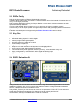
10.1 RSP_Eval-Kit
This evaluation kit demonstrates applications of RSP1 with a large number of K-LCx sensor devices.
It is fully documented including schematics and PCB layout.
Indicators
D1
D2
D3
Power LED
Busy LED (start-up)
Detection LED
Connectors
X1
X2
X3
X4
X5
X6
X7a
X7b
Xp
K-LCx sensor connector
Backside K-LCx connector
K-MCx sensor connector
Digital output connector
DC Supply input 6 .. 12V
Digital I/O (SPI in preparation)
Serial Command (RSP_Terminal)
Serial Debug (RSP_Scope)
Reserved / Reset
Settings
P1
P2
SW
J1
J2
Sensitivity pot
Hold time pot
Mode switch
Sensor supply volage
Optional for mono sensor
Fig. 12: RSP1 Evaluation Kit
Evaluation kit contains the following software tools:
10.1.1 RSP_Terminal Software
This Windows software allows exploring and setting RSP1 parameters via the serial "Host command
Interface".
10.1.2 RSP_Scope Software
This Windows software is a virtual oscilloscope for viewing internal FFT signals, thresholds, I/Q time
domain signals.
It also allows setting parameters and exploring graphically their function.
10.1.3 RSP_Prog Software
This Windows software allows RSP parameter exchange with a PC.
It also includes an RSP1 chip software update utility.
© RFbeam Microwave GmbH www.rfbeam.ch
18/25
RFbeam Microwave GmbH
RSP1 Radar Processor
Preliminary Datasheet
11 Electrical Data
11.1 Power Supply
Parameter
Symbol
Min
Typ
Max
Unit
Digital supply voltage digital
Conditions
Vcc
3.0
3.3
3.5
V
Analog supply voltage
AVcc
3.0
3.3
Vcc + 05.
V
Digital supply current
IVcc
12
15
Analog supply current
AIVcc
3
mA
mA
11.2 Analog I/O
Parameter
Conditions
Symbol
Min
ADC Resolution
Sampling rate
Typ
Max
12
adjustable by parameter S03
1.280
Reference input voltage range
1.6
Reference input resistance
10
Radar Input type
--
bit
22.528
1.65
Unit
1.7
kHz
V
MΩ
differential
--
--
Radar input sensitivity
Gain = 1, VREF = 1.65V
A1
860
µV/bit
Radar input sensitivity
Gain = 16, VREF = 1.65V
A16
54
µV/bit
4
kΩ
Radar Input impedance
Radar Input capacitance
10
Potentiometer input impedance
Potentiometer input range
100k
VREF = 1.65V
0
pF
kΩ
VREF
V
Max
Unit
11.3 Digital I/O
Parameter
Conditions
Symbol
Min
Input voltage high
VIH
2
Input voltage low
VIL
-0.3
Input currents
IIH,
Output current
IOH, IOL
-20
Output voltage high
IOH = -8mA
VOH
2.6
Output voltage low
IOL = 10mA
VOL
© RFbeam Microwave GmbH www.rfbeam.ch
Typ
VCC + 0.3V V
0.8
V
140
µA
20
mA
2.9
0.4
V
0.76
V
19/25
RFbeam Microwave GmbH
RSP1 Radar Processor
Preliminary Datasheet
12 Pin Configuration
U?
Sensor
39
40
41
42
43
44
1
2
3
6
36
37
AVCC
SENSOR_VCO
SAMPLE_HOLD
nSENSOR_PWR
DNC
Power
9
19
31
8
18
30
38
RFbeam ®
RSP1
RADAR_AREF
DNC
ALT_RADAR_COMMON
RADAR_COMMON
RADAR_I1
RADAR_Q1
ALT_RADAR_I1
ALT_RADAR_Q1
Reserved
7
U?
VCC
VCC
VCC
Potentiometer
HOLD_POT
SENS_POT
USE_POTIS
4
5
16
D I/O
ID0 / SENSOR_MONO
ID1 / DIR_MONO
ID2 / DIR_BACKWARD
ID3 / IMMUNITY
SETTING_MODE
LED_BUSY
LED_DETECT
DETECT_OUT
LOW_BANDWIDTH
28
29
32
33
20
10
11
15
14
39
40
41
42
43
44
1
2
3
6
36
37
Host Interface
CMD_TX_ENABLE
CMD_RX
CMD_TX
DETECT_SIGNAL
SPI SS
SPI SCK
SPI MOSI
SPI MISO
Debug
GND
GND
GND
GND
Sensor
DEBUG_RX
DEBUG_TX
PDI/PDI_DATA
RESET/PDI_CLK
21
22
23
17
24
27
25
26
12
13
34
35
RSP1_TQFP
Standard RSP1 package: 44 pin TQFP
AVCC
SENSOR_VCO
SAMPLE_HOLD
nSENSOR_PWR
DNC
Power
9
19
31
8
18
30
38
45
RSP1
RADAR_AREF
DNC
ALT_RADAR_COMMON
RADAR_COMMON
RADAR_I1
RADAR_Q1
ALT_RADAR_I1
ALT_RADAR_Q1
Reserved
7
RFbeam ®
VCC
VCC
VCC
Potentiometer
HOLD_POT
SENS_POT
USE_POTIS
D I/O
ID0 / SENSOR_MONO
ID1 / DIR_MONO
ID2 / DIR_BACKWARD
ID3 / IMMUNITY
SETTING_MODE
LED_BUSY
LED_DETECT
DETECT_OUT
LOW_BANDWIDTH
28
29
32
33
20
10
11
15
14
Host Interface
CMD_TX_ENABLE
CMD_RX
CMD_TX
DETECT_SIGNAL
SPI SS
SPI SCK
SPI MOSI
SPI MISO
Debug
GND
GND
GND
GND
Exposed Pad
4
5
16
DEBUG_RX
DEBUG_TX
PDI/PDI_DATA
RESET/PDI_CLK
21
22
23
17
24
27
25
26
12
13
34
35
RSP1_QFN
On request: 45 pin QFN package
Fig. 13: RSP1 Pin Configuration: left TQFP case, right QFN case
© RFbeam Microwave GmbH www.rfbeam.ch
20/25
RFbeam Microwave GmbH
RSP1 Radar Processor
Preliminary Datasheet
13 Sample Schematics
For complete schematics, please refer to the RSP1_Eval-Kit user manual.
13.1 Amplifiers
13.1.1 Sensor Outputs
A moving object in range of a Radar sensor (often called “transceiver “) generates a low frequency output
signal. Frequency depends on the object speed. Amplitude depends on distance, reflectivity and size of
the object. Doppler frequency fd is proportional to the object speed v:
or
44Hz
f d =v⋅
⋅cos α
km/ h
158Hz
f d =v⋅
⋅cos α
m/ s
α
with
moving
object
Radar sensor
Note that the angle of the moving object reduces Doppler frequency.
Radar sensor signals have low frequency outputs called 'IF' outputs.
Most sensors of the K-LCx family do not have an integrated amplifier. This makes these devices
universal and low cost. Different applications need different amplification and frequency response.
Sensor output amplitude can range from less than 100nV to some mV .
13.1.2 Amplifier Structures
The following example schematics show 2 channel (I/Q) solutions with one- and two stage amplifiers.
Dual channel configurations need I/Q (sometimes called "stereo" sensors) like K-LC2, K-LC5, K-LC6 etc.
Dual channel configurations are state-of-the-art solutions with much better noise and interference
suppression than single channel solutions. Furthermore, dual channel allows distinguishing approaching
and receding objects.
Please refer also to Table 4: Useful signal level conversions.
Single channel solutions need less components and can be used with low cost sensors like K-LC1 or
K-LC3.
If only 1 channel is required, only amp of channel 'I' is is needed, but RSP1 inputs 'RADAR_I1'
and 'RADAR_Q1' must be connected together.
RSP1 provides an internal programmable gain amplifier with gains from 1 to 32 (0dB to 30dB).
Gain is set by parameter 'S09'. Default setting is 32.
Atotal =Aintern⋅Aextern - > in our examples
Atotal =16⋅500=8'000 or 24dB+54dB=78dB
Maximum detection range is a function of the signal/noise (S/N) ratio at the RSP1 input.
Higher gain does not automatically mean higher detection range.
For more details on optimal amplification refer to the RSP1_Eval-Kit manual.
Dual amp stage structures allow higher external gains, higher bandwidth and lower gain.
If high speed detection at maximum range is required, dual amp stage is the right choice.
© RFbeam Microwave GmbH www.rfbeam.ch
21/25
RFbeam Microwave GmbH
RSP1 Radar Processor
Preliminary Datasheet
13.1.3 Single Amp, 2 Channels
Example for speed ranges from 0.1km/h up to 180km/h. This configuration needs the RSP1 internal gain stage with A = 16 (24dB)
Fig. 14: Single Amp example for K-LCx sensors. Channel Q circuit is equivalent to channel I
Bandwidth (-3dB) C1 *) C7 *)
Op-Amp Type Amp Gain
5Hz … 1kHz
15nF
120nF LMV772
54dB (A = 500)
5Hz … 8kHz
15pF
15nF
54dB (A = 500)
LMP7716
*) For Q channel, same capacitor values
© RFbeam Microwave GmbH www.rfbeam.ch
22/25
RFbeam Microwave GmbH
RSP1 Radar Processor
Preliminary Datasheet
13.1.4 Dual Amp, 2 Channels
Example for speed ranges from 0.1km/h up to 250km/h. This configuration results in better S/N ratio and higher bandwidth than Single Amp solution
Fig. 15: Dual Amp example for K-LCx sensors. Channel Q circuit is equivalent to channel I.
Bandwidth
Speed range
C6, C7 C1, C2 R1, R2 Op-Amp
Amp Gain
5Hz … 500Hz
3cm/s 3m/s
2.2uF
15nF
120nF
LMV774
72dB (A = 15'800 ) Person detection
Typical Application
400Hz … 12kHz
0.9 .. 270 km/h
33nF
10pF
15nF
LMP7716 72dB (A = 15'800)
Car speed or detection
For Q channel, same component values apply
© RFbeam Microwave GmbH www.rfbeam.ch
23/25
RFbeam Microwave GmbH
RSP1 Radar Processor
Preliminary Datasheet
13.2 Control Input Output
Please note: digital I/O are all 3.3V types.
13.2.1 Peripheral IO
All inputs are tied by a pull down resistor to ground.
All outputs switch to Vcc 3.3V.
Fig. 16: Stand alone configuration, control elements
Isolated output is preferable in order to prevent ground loops and noise injection.
Fig. 17: Example of isolated digital output
© RFbeam Microwave GmbH www.rfbeam.ch
24/25
RFbeam Microwave GmbH
RSP1 Radar Processor
Preliminary Datasheet
14 Ordering Information
RSP1 processor in 44-pin TQFP case
RSP1 processor in 45-Pin QFN case
RSP1 evaluation Kit
RSP1-TQFP
RSP1-QFN (on request for high volume production)
RSP1_Eval-Kit
15 Revision History
Version 0.1
Version 0.2
Version 0.3
Version 0.4
Mai 10, 2014
August 13, 2014
Sept 18, 2014
Nov 04, 2014
Preliminary release
Preliminary release 2
Preliminary release 3
Preliminary release 4, valid from software version V1.7
RFbeam does not assume any responsibility for use of any circuitry described, no circuit patent licenses are implied and
RFbeam reserves the right at any time without notice to change said circuitry and specifications.
© RFbeam Microwave GmbH www.rfbeam.ch
25/25