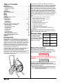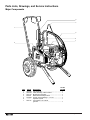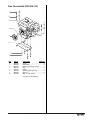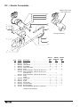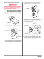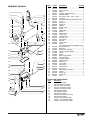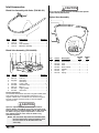
1
Owner’s Manual
For professional use only
Do not use this equipment before reading this manual!
PowrTwin 3500
50th Anniversary Special
Model Number:
Gas Bare
Printed in the U. S. A.
335-580
NOTE: This manual contains important warnings
and instructions. Please read and retain for
reference.
0401 © 2001 Titan Tool Inc. All rights reserved. Form No. 313-1733, REV A
Table of Contents
This PowrTwin is equipped with Speeflo's exclusive and
patented Severe Service 500™ fluid pump. This technology
will give you significantly longer rod, cylinder, and packing life
than any other sprayer built in the world. This double ball
piston pump employs a dependable and durable time-tested
design. All pumps use an exclusive thick hard chrome plating
on rod and cylinder parts. This patented plating process is
harder than nitralloy, stainless steel, or hard chrome used by
any other paint pump manufacturer and much more abrasion
resistant. Highly polished parts reduce friction, extend packing
life, and avoid damage from corrosion and abrasion. More
than 100,000 of these pumps are in operation around the
world.
This PowrTwin offers other cost saving features:
• Freeze-proof pressure control
• Choice of power — gas, electric, or both
• Tungsten carbide valve seats
• Self-adjusting packings
• Exclusive hand-tight swivel foot valve
• Large capacity inline paint filter
• Waterborne compatible
• "Floating Ball" pressure bleed valve
• 5 gallon siphon hose and bleed line assemblies are
standard
You have made an excellent choice. We know you will be
pleased with your new PowrTwin. Thanks again for selecting
Speeflo. We appreciate your business.
Introduction. . . . . . . . . . . . . . . . . . . . . . . . . . . . . . . . . . . . . 2
Safety Precautions . . . . . . . . . . . . . . . . . . . . . . . . . . . . . . . 2
Grounding Instructions. . . . . . . . . . . . . . . . . . . . . . . . . . . . 4
Gasoline Engine Safety . . . . . . . . . . . . . . . . . . . . . . . . . . . 4
Français . . . . . . . . . . . . . . . . . . . . . . . . . . . . . . . . . . . . . 14
Español . . . . . . . . . . . . . . . . . . . . . . . . . . . . . . . . . . . . . . 16
Specifications . . . . . . . . . . . . . . . . . . . . . . . . . . . . . . . . . . . 5
Operating Components . . . . . . . . . . . . . . . . . . . . . . . . . . . 6
Setup . . . . . . . . . . . . . . . . . . . . . . . . . . . . . . . . . . . . . . . . . . 7
Fueling . . . . . . . . . . . . . . . . . . . . . . . . . . . . . . . . . . . . . . . . 7
Startup. . . . . . . . . . . . . . . . . . . . . . . . . . . . . . . . . . . . . . . . . 8
Cleanup . . . . . . . . . . . . . . . . . . . . . . . . . . . . . . . . . . . . . . . . 9
Pressure Relief Procedure. . . . . . . . . . . . . . . . . . . . . . . . . 9
Maintenance . . . . . . . . . . . . . . . . . . . . . . . . . . . . . . . . . . . . 9
Troubleshooting . . . . . . . . . . . . . . . . . . . . . . . . . . . . . 11–13
Airless Gun . . . . . . . . . . . . . . . . . . . . . . . . . . . . . . . . . . . 11
Fluid Pumps . . . . . . . . . . . . . . . . . . . . . . . . . . . . . . . . . . 11
Hydraulic Motors . . . . . . . . . . . . . . . . . . . . . . . . . . . . . . . 12
Spray Patterns . . . . . . . . . . . . . . . . . . . . . . . . . . . . . . . . 13
Parts Lists and Service Instructions . . . . . . . . . . . . . 18–31
Main Assembly — Gas Models . . . . . . . . . . . . . . . . . . . . 18
Gas Convertokit. . . . . . . . . . . . . . . . . . . . . . . . . . . . . . . . 19
DC— Electric Convertokit . . . . . . . . . . . . . . . . . . . . . . . . 20
Cart Assembly . . . . . . . . . . . . . . . . . . . . . . . . . . . . . . . . . 22
Hydraulic System . . . . . . . . . . . . . . . . . . . . . . . . . . . . . . 23
Hydraulic Motor . . . . . . . . . . . . . . . . . . . . . . . . . . . . . 24–26
Fluid Pump . . . . . . . . . . . . . . . . . . . . . . . . . . . . . . . . 26–27
Inlet Accessories . . . . . . . . . . . . . . . . . . . . . . . . . . . . . . . 28
Outlet Accessories. . . . . . . . . . . . . . . . . . . . . . . . . . . . . . 29
SAE O-Ring Fitting Installation. . . . . . . . . . . . . . . . . . . . . 31
Key Accessories and Service Kits . . . . . . . . . . . . . . . . . . 31
Airless Tip Selection . . . . . . . . . . . . . . . . . . . . . . . . . . . . 31
Warranty . . . . . . . . . . . . . . . . . . . . . . . . . . . . . . . . . . . . . . 32
Warning Labels
Your sprayer has the English
language warning label. If
you require this label in
French, German, or Spanish,
or require additional English
labels, order directly from
Speeflo free of charge.
Introduction
Congratulations on having selected the finest airless sprayer
available in the world. Speeflo piston pumps are tireless
workhorses — so tough they are virtually indestructible, even
under the most severe service. Speeflo designs and builds
equipment with superior quality and reliability. Equipment that
will last for years with minimal maintenance and downtime.
This equipment will make you money year after year. We
thank you for your purchase and welcome you to our large
and growing family of Speeflo users.
The unique ability of this PowrTwin to operate with either gas
or electric power provides you with the flexibility to work
indoors or outside where no electricity is available.
Hydraulic drive makes possible the longest stroke and slowest
cycling pumps in the industry, which translates into low
maintenance and longer life. Electric units operate quietly with
no motor starting and stopping.
Part #
Language
313-771
313-784
English
313-1306
313-1307
Spanish
313-785
313-786
French
313-787
313-788
German
Safety Precautions
This manual contains information that must be read and
understood before using the equipment. When you come to
an area that has one of the following symbols, pay particular
attention and make certain to heed the safeguard.
WARNING
This symbol indicates a potential hazard that may cause
serious injury or loss of life. Important safety information
will follow.
CAUTION
This symbol indicates a potential hazard to you or to the
equipment. Important information that tells how to
prevent damage to the equipment or how to avoid causes
of minor injuries will follow.
NOTE: Notes give important information that should
be given special attention.
2
© Titan Tool Inc. All rights reserved.
• Always flush unit into a separate metal container, at low
pump pressure, with spray tip removed. Hold gun firmly
against side of container to ground container and prevent
static sparks.
• Follow the material and solvent manufacturer's warnings
and instructions.
• Use extreme caution when using materials with a
flashpoint below 70° F (21° C). Flashpoint is the
temperature that a fluid can produce enough vapors to
ignite.
• Plastic can cause static sparks. Never hang plastic to
enclose a spray area. Do not use plastic drop cloths
when spraying flammable materials.
• Use lowest possible pressure to flush equipment.
GAS ENGINE (WHERE APPLICABLE)
Always place pump outside of structure in fresh air. Keep all
solvents away from the engine exhaust. Never fill fuel tank
with a running or hot engine. Hot surface can ignite spilled
fuel. Always attach ground wire from pump unit to a grounded
object, such as a metal water pipe. Refer to engine owner’s
manual for complete safety information.
HAZARD: EXPLOSION HAZARD DUE TO INCOMPATIBLE
MATERIALS - Will cause severe injury or
property damage.
PREVENTION:
• Do not use materials containing bleach or chlorine.
• Do not use halogenated hydrocarbon solvents such as
mildewcide, methylene chloride and 1,1,1 trichloroethane. They are not compatible with aluminum.
• Contact your coating supplier about the compatibility of
material with aluminum.
HAZARD: HAZARDOUS VAPORS - Paints, solvents,
insecticides, and other materials can be
harmful if inhaled or come in contact with the
body. Vapors can cause severe nausea,
fainting, or poisoning.
PREVENTION:
• Use a respirator or mask if vapors can be inhaled. Read
all instructions supplied with the mask to be sure it will
provide the necessary protection.
• Wear protective eyewear.
• Wear protective clothing as required by coating
manufacturer.
HAZARD: GENERAL - This product can cause severe
injury or property damage.
PREVENTION:
• Read all instructions and safety precautions before
operating equipment.
• Always disconnect the motor from the power supply
before working on the equipment (electric models only).
• Follow all appropriate local, state, and national codes
governing ventilation, fire prevention, and operation.
• The United States Government Safety Standards have
been adopted under the Occupational Safety and Health
Act (OSHA). These standards, particularly part 1910 of
the General Standards and part 1926 of the Construction
Standards should be consulted.
• Use only manufacturer authorized parts. User assumes
all risks and liabilities when using parts that do not meet
the minimum specifications and safety devices of the
pump manufacturer.
• Before each use, check all hoses for cuts, leaks,
abrasion or bulging of cover. Check for damage or
movement of couplings. Immediately replace the hose if
any of these conditions exist. Never repair a paint hose.
Replace it with another grounded high-pressure hose.
• All hoses, swivels, guns, and accessories must be
pressure rated at or above 3300PSI/228 BAR.
• Do not spray outdoors on windy days.
• Wear clothing to keep paint off skin and hair.
WARNING
HAZARD: Injection injury - A high pressure stream
produced by this equipment can pierce the
skin and underlying tissues, leading to serious
injury and possible amputation. See a
physician immediately.
DO NOT TREAT AN INJECTION INJURY AS A SIMPLE
CUT! Injection can lead to amputation. See a physician
immediately.
The maximum operating range of the gun is 3300 PSI /
228BAR fluid pressure.
PREVENTION:
• NEVER aim the gun at any part of the body.
• NEVER allow any part of the body to touch the fluid
stream. DO NOT allow body to touch a leak in the fluid
hose.
• NEVER put your hand in front of the gun. Gloves will not
provide protection against an injection injury.
• ALWAYS lock the gun trigger, shut the pump off, and release
all pressure before servicing, cleaning the tip or guard,
changing tip, or leaving unattended. Pressure will not be
released by turning off the motor. The PRIME/SPRAY knob
must be turned to PRIME to relieve the pressure. Refer to
the PRESSURE RELIEF PRESSURE described in the pump
manual.
• ALWAYS keep the tip guard in place while spraying. The
tip guard provides some protection but is mainly a
warning device.
• ALWAYS remove the spray tip before flushing or cleaning
the system.
• The paint hose can develop leaks from wear, kinking and
abuse. A leak can inject material into the skin. Inspect
the hose before each use.
• NEVER use a spray gun without a trigger lock and trigger
guard in place and in good working order.
• All accessories must be rated at or above 3300 PSI / 228
BAR. This includes spray tips, guns, extensions, and
hose.
NOTE TO PHYSICIAN:
Injection into the skin is a traumatic injury. It is
important to treat the injury as soon as possible. DO
NOT delay treatment to research toxicity. Toxicity is a
concern with some coatings injected directly into the
blood stream. Consultation with a plastic surgeon or
reconstructive hand surgeon may be advisable.
HAZARD: EXPLOSION OR FIRE - Solvent and paint fumes
can explode or ignite. Severe injury and/or
property damage can occur.
PREVENTION:
• Provide extensive exhaust and fresh air introduction to
keep the air within the spray area free from accumulation
of flammable vapors.
• Avoid all ignition sources such as static electric sparks,
open flames, pilot lights, and hot objects. Connecting or
disconnecting power cords or working light switches can
make sparks.
• Do not smoke in spray area.
• Fire extinguisher must be present and in good working
order.
• Place paint pump in a well ventilated area. Flammable
vapors are often heavier than air. Floor area must be
extremely well ventilated. The paint pump contains arcing
parts that emit spark and can ignite vapors.
• The equipment and objects in and around the spray area
must be properly grounded to prevent static sparks.
• Use only conductive or grounded high pressure fluid hose.
Gun must be grounded through hose connections.
• Power cord must be connected to a grounded circuit
(electric models only).
© Titan Tool Inc. All rights reserved.
3
Grounding Instructions
Gasoline Engine Safety
Electric models must be grounded. In the event of an
electrical short circuit, grounding reduces the risk of electric
shock by providing an escape wire for the electric current.
This product is equipped with a cord having a grounding wire
with an appropriate grounding plug. The plug must be
plugged into an outlet that is properly installed and grounded
in accordance with all local codes and ordinances.
DANGER — Improper installation of the grounding plug can
result in a risk of electric shock. If repair or replacement of the
cord or plug is necessary, do not connect the green grounding
wire to either flat blade terminal. The wire with insulation
having a green outer surface with or without yellow stripes is
the grounding wire and must be connected to the grounding
pin.
Check with a qualified electrician or serviceman if the
grounding instructions are not completely understood, or if you
are in doubt as to whether the product is properly grounded.
Do not modify the plug provided. If the plug will not fit the
outlet, have the proper outlet installed by a qualified
electrician.
This product is rated more than 15 amperes and is for use on
a circuit having a nominal rating of 120 volts, or the product is
for use on a circuit having a nominal rating more than 120
volts, and is factory-equipped with a specific electric cord and
plug to permit connection to a proper electric circuit. Make
sure that the product is connected to an outlet having the
same configuration as the plug. No adapter should be used
with this product. If the product must be reconnected for use
on a different type of electric circuit, the reconnection should
be made by qualified service personnel.
WARNING
The engine exhaust from this unit contains chemicals
known to the State of California to cause cancer, birth
defects, or other reproductive harm.
1. Honda engines are designed to give safe and dependable
service if operated according to instructions. Read and
understand the Honda Owner's Manual before operating
the engine. Failure to do so could result in personal injury
or equipment damage.
2. To prevent fire hazards and to provide adequate
ventilation, keep the engine at least 1 meter (3 feet) away
from buildings and other equipment during operation. Do
not place flammable objects close to the engine.
3. Children and pets must be kept away from the area of
operation due to a possibility of burns from hot engine
components or injury from any equipment the engine may
be used to operate.
4. Know how to stop the engine quickly, and understand the
operation of all controls. Never permit anyone to operate
the engine without proper instructions.
5. Gasoline is extremely flammable and is explosive under
certain conditions.
6. Refuel in a well-ventilated area with the engine stopped.
Do not smoke or allow flames or sparks in the refueling
area or where gasoline is stored.
7. Do not overfill the fuel tank. After refueling, make sure
the tank cap is closed properly and securely.
8. Be careful not to spill fuel when refueling. Fuel vapor or
spilled fuel may ignite. If any fuel is spilled, make sure
the area is dry before starting the engine.
9. Never run the engine in an enclosed or confined area.
Exhaust contains poisonous carbon monoxide gas;
exposure may cause loss of consciousness and may lead
to death.
10. The muffler becomes very hot during operation and
remains hot for a while after stopping the engine. Be
careful not to touch the muffler while it is hot. To avoid
severe burns or fire hazards, let the engine cool before
transporting it or storing it indoors.
11. Never ship/transport unit with gasoline in the tank.
CAUTION
Use only a 3-wire extension cord that has a 3-blade
grounding plug and a 3-slot receptacle that will accept the
plug on the product. Make sure your extension cord is in
good condition. When using an extension cord, be sure
to use one heavy enough to carry the current your
product will draw. An undersized cord will cause a drop
in line voltage resulting in loss of power and overheating.
For lengths less than 50 feet, No. 12 AWG extension cords
should be used. If an extension cord is to be used
outdoors, it must be marked with the suffix W-A after the
cord type designation. For example, a designation of
SJTW-A would indicate that the cord would be appropriate
for outdoor use.
WARNING
DO NOT use this equipment to spray water or acid.
CAUTION
Do not lift by cart handle when loading or unloading.
4
© Titan Tool Inc. All rights reserved.
Specifications
Delivery (GPM)
(LPM)
Cycles per gallon
Cycles per liter
Cycles per minute (maximum)
Maximum Tip Size - 1 Gun
Maximum Tip Size - 2 Guns
Maximum Tip Size - 3 Guns
Pressure Range (psi)
Pressure Range (bar)
Power
Fuel Capacity
Halogenated Solvent Compatible
Weight
Inlet Paint Filter
Outlet Paint Filter
Pump Inlet
Pump Outlet
Paint Filter Hose Connections
Dimensions
Fluid Pump Wetted Parts
Gas Units
1.2
4.5
87
23
104
.034"
.025"
.019"
400 - 3300
28 - 228
Honda 4.0 HP, 4-Stroke,
Single Cylinder, Overhead Valve Engine With Oil Alert
0.66 US Gallons
(Approximately 3 hours run time)
Yes
139 Lbs. (63 Kg.)
10 Mesh "Rock Catcher"
50 Mesh, 18 in.2
3/4" NPT(F)
1/2" NPT(F) to Paint Filter
(1) - 1/4" NPS(M)
(1) - 3/8" NPT(F) Plugged
30" H (787 mm) x 34" L (864 mm) x 23" W (584 mm)
Electroless nickel plated ductile iron, electroless nickel plated carbon steel, proprietary Severe Service 500™ hard chrome anti-wear surface, stainless steel, tungsten
carbide, 37)(, thiokol impregnated leather, ultra high molecular weight polyethylene.
Electric Units
Delivery (GPM)
(LPM)
Cycles per gallon
Cycles per liter
Cycles per minute (maximum)
Maximum Tip Size - 1 Gun
Maximum Tip Size - 2 Guns
Maximum Tip Size - 3 Guns
Pressure Range (psi)
Pressure Range (bar)
Power
Halogenated Solvent Compatible
Weight
Inlet Paint Filter
Outlet Paint Filter
Pump Inlet
Pump Outlet
Paint Filter Hose Connections
Dimensions
Fluid Pump Wetted Parts
© Titan Tool Inc. All rights reserved.
DC - Electric
1.10
4.20
87
23
96
.031"
.023"
.017"
400 - 3300
28 - 228
2 HP DC Motor
115V, 16 AMP
230V, 8 AMP
Overload Protected
Yes
158 Lbs. (72 Kg.)
10 Mesh "Rock Catcher"
50 Mesh, 18 in.2
3/4" NPT(F)
1/2" NPT(F) to Paint Filter
(1) - 1/4" NPS(M)
(1) - 3/8" NPT(F) Plugged
30" H (787 mm) x 34" L (864 mm) x 23" W (584 mm)
Electroless nickel plated ductile iron, electroless nickel plated carbon steel, proprietary Severe Service 500™ hard chrome anti-wear surface, stainless steel, tungsten
carbide, 37)( thiokol impregnated leather, ultra high molecular weight polyethylene.
5
Operating Components
Siphon Hose
Bleed Line
Hydraulic Filter
Pressure
Adjustment
Knob
Hydraulic Motor
Muffler
Hose Rack
Hydraulic
Bypass Valve
Choke
Hydraulic Fluid
Fill and Dipstick
Snap Down
Handle Buttons
Paint Filter
Engine ON/OFF
Switch
Hydraulic
Reservoir
Connecting Pin
Grounding Lug
Wet Cup
Hydraulic Return
Hose
Hydraulic
Shut-Off
Valve
Hydraulic
Pressure Hose
Siphon Hose
Fluid Pump
6
© Titan Tool Inc. All rights reserved.
Setup
If the unit is being operated in an area that is overloaded
by other appliances or low voltage conditions, it is
important to start the unit "unloaded." Tip the electric
motor forward so that the belt is loosened and the motor
starts without full load. This reduces the amperage draw
on starting and may avoid tripping the circuit breaker.
7. Be sure the PowrTwin system is grounded. All Speeflo
units are equipped with a grounding lug. A grounding
cable (not supplied) should be used to connect the unit to
a true earth ground. Check your local electrical
regulations for detailed grounding instructions. See the
Accessories and Service Kits section near the back of this
manual for ordering information.
8. Strain all paints with a nylon strainer to ensure trouble free
operation and freedom from frequent cleaning of the inlet
screen and gun strainer.
WARNING
Read, understand, and follow all warnings before starting
or operating this sprayer.
1. Connecting the Hoses:
The siphon hose and the bleed line hose have factory
installed 37)( tape on the male end of the hoses.
Tighten the syphon hose and bleed line wrench tight.
WARNING
Bleed Line
Connection
Proper grounding is important. This applies to both gas
and electric powered models. The passage of some
materials through the nylon fluid hose will build up a
static electric charge, which if discharged, could ignite
solvent vapors present and create an explosion.
Fueling
Siphon Hose
WARNING
Gasoline is extremely flammable and is explosive under
certain conditions.
• ALWAYS turn the engine off before refueling.
• Refuel in a well-ventilated area.
• Do not smoke or allow flames or sparks in the refueling
area or where gasoline is stored.
• Do not overfill the fuel tank. After refueling, make sure the
tank cap is closed properly and securely.
• Be careful not to spill fuel when refueling. Spilled fuel or
fuel vapor may ignite. If any fuel is spilled, make sure the
area is dry before starting the engine.
• Avoid repeated or prolonged contact with skin or breathing
of vapor.
• Keep out of the reach of children.
2. One Gun Operation - Attach the gun and hose. Always
use a spray hose at least 50 feet long. Do not use 37)(
or thread sealant on this assembly. Do not install the
spray tip at this time.
3. Two Gun Operation - Remove the plug from the second
gun outlet. Connect a hose and a gun to the outlet.
4. Multiple Gun Operation - This unit is engineered to handle
up to 3 guns with .019" tips. When using more than two
guns, make sure the second gun hookup outlet is
plugged. Connect the multiple gun manifold to the single
gun outlet. These manifolds are for either 2, 3, or 4-guns
and have shut off valves. Connect a hose and gun to
each outlet.
Fuel Specifications
• Use automotive gasoline that has a pump octane number
of 86 or higher, or that has a research octane number of
91 or higher.
• Unleaded fuel produces fewer engine and spark plug
deposits and extends the life of exhaust system
components.
• Never use stale or contaminated gasoline or an
oil/gasoline mixture. Avoid getting dirt, dust or water in the
fuel tank. Use of a lower octane gasoline can cause
persistent "pinging" or heavy "spark knock" (a metallic
rapping noise) which, if severe, can lead to engine
damage.
NOTE: If "spark knock" or "pinging" occurs at a
steady engine speed under normal load,
change brands of gasoline. If spark knock or
pinging persists, consult your authorized
Honda dealer. Failure to do so is considered
misuse, and damage caused by misuse is not
covered by the engine manufacturer’s limited
warranty.
Occasionally you may experience light spark
knock while operating under heavy loads. This
is no cause for concern, it simply means your
engine is operating efficiently.
5. Fill the wet-cup 1/2 full with Speeflo Piston Lube (P/N 700925) supplied by the factory. This extends packing life.
6. Electric Models - Use a 20 amp service outlet. Always
locate the electric model within 10 to 15 feet of the service
outlet. Use a short electric cable and a long paint hose.
Any extension cord will create some voltage drop. If an
extension cord is necessary, use only grounded 3 wire #
12 extension cords.
© Titan Tool Inc. All rights reserved.
7
Gasolines Containing Alcohol
Pressure Control
Knob
If you decide to use a gasoline containing alcohol (gasohol),
be sure its octane rating is at least as high as that
recommended by the engine manufacturer. There are two
types of "gasohol": one containing ethanol, and the other
containing methanol. Do not use gasohol that contains more
than 10% ethanol. Do not use gasoline containing methanol
(methyl or wood alcohol) that does not also contain cosolvents and corrosion inhibitors for methanol. Never use
gasoline containing more than 5% methanol, even if it has cosolvents and corrosion inhibitors.
Shut-Off Valve
NOTE: Fuel system damage or engine performance
problems resulting from the use of fuels that
contain alcohol is not covered under the
warranty. The engine manufacturer cannot
endorse the use of fuels containing methanol
since evidence of their suitability is incomplete
at this time.
Before buying gasoline from an unfamiliar
station, try to find out if the gasoline contains
alcohol. If it does, confirm the type and
percentage of alcohol used. If you notice any
undesirable operating characteristics while
using a gasoline that contains alcohol, or one
that you think contains alcohol, switch to a
gasoline that you know does not contain
alcohol.
5. Turn the pressure control knob counterclockwise (as
viewed from top) to its lowest pressure setting.
6. Open the pressure bleed valve by turning it
counterclockwise. This relieves pressure.
Pressure Bleed
Valve
Startup
1. Areas must be well ventilated to prevent hazardous
operation with volatile solvents or exhaust fumes.
WARNING
If lacquer or other flammable materials are to be sprayed,
ALWAYS locate the unit outside the immediate spraying
area. Failure to do so may cause an explosion.
2. Locate the unit outside the immediate spraying area to
avoid clogged air intake of the engine or electric motor
with overspray.
3. Before starting the unit. check oil levels.
a. The hydraulic fluid level should read "Full" on the
dipstick. CHECK IT REGULARLY. See “Hydraulic
System” in the Maintenance section of this manual for
changing or adding hydraulic fluid. Do not overfill. Use
only Speeflo Coolflo™ Hydraulic Fluid (P/N 430-361).
b. The gasoline engine oil level is determined by the
manufacturer. Check the manufacturer's service
manual supplied.
CAUTION
Use of Speeflo's Coolflo™ Hydraulic Fluid is mandatory in
the PowrTwin hydraulic system. Do not use any other
hydraulic fluid. Use of any other hydraulic fluid may
seriously damage hydraulic system and will void warranty.
4. Open the orange-handled hydraulic shut-off valve located on
the hydraulic pressure hose. The handle should be in line
with the hose. The figure below shows the handle in the
open position.
7.
8.
9.
10.
8
a. Your new sprayer was tested at the factory with mineral
spirits. You must clean the system before spraying to
avoid contamination of the sprayed material.
If you are spraying a water based latex, flush with
warm, soapy water followed by a clean water rinse. If
you are using any other coating, flush with warm, soapy
water followed by a solvent. Check with the material
manufacturer for a compatible solvent. Place syphon
tube assembly into proper solvent or water.
b. Place waste container below bleed line.
c. Start engine or electric motor. Turn the pressure
control adjustment knob clockwise (increasing
pressure) until pump cycles evenly and solvent flows
freely from bleed line.
d. Close the pressure bleed valve by turning it clockwise.
This allows the system to pressurize. Hold the gun
trigger open, without spray tip attached, until the fluid
flows smoothly.
Repeat above starting procedure with paint material. Lock
gun trigger and attach spray tip. Refer to the spray gun’s
Technical Data Sheet or Owner's Manual for tip installation
and selection of the proper tip size.
Test spray pattern. Operate the pump at the lowest
hydraulic pressure which provides good atomization. See
the Troubleshooting section in this manual if you are not
getting the proper pattern.
Operating pressure is adjustable from 400 to 3300 psi
(228 bar) by turning the pressure control knob clockwise.
Do not turn the knob clockwise more than necessary to
provide satisfactory atomization. Excess pressure wears
out spray tips.
When restarting the unit, reduce the pressure at the
pressure control adjustment knob and the pressure bleed
valve.
© Titan Tool Inc. All rights reserved.
Cleanup
Color Change/Clean Out
WARNING
CAUTION
Use only compatible solvents when cleaning out oil based
enamels, lacquers, coal tar, and epoxies. Check with the
fluid manufacturer for the recommended solvent.
1. Reduce pressure by turning the pressure control knob and
the pressure bleed valve on the bleed line
counterclockwise. Follow the “Pressure Relief Procedure”
above. The pressure bleed valve should be turned
counterclockwise at least three full turns.
Special cleanup instructions for use with flammable
solvents:
• Always flush spray gun preferably outside and at
least one hose length from spray pump.
• If collecting flushed solvents in a one gallon metal
container, place it into an empty five gallon metal
container, then flush solvents.
• Area must be free of flammable vapors.
• Follow all cleanup instructions.
Pressure Relief Procedure
Pressure Bleed
Valve
WARNING
Always reduce pressure when you are cleaning a clogged
tip, changing a tip, servicing any part of the system, or
shutting down. Follow the steps below:
1. Engage the gun trigger lock.
2. Shut off the power source.
3. Close the orange-handled hydraulic shut-off valve on the
hydraulic pressure hose.
4. Open the pressure bleed valve by turning it
counterclockwise at least three full turns.
5. Disengage the gun trigger lock and hold trigger open until
flow of material stops.
6. Be certain to hold a metal part of the gun firmly to the side
of a grounded metal container.
2. Pull the siphon tube out of the material container.
3. Remove the spray tip from the gun. Hold the gun trigger
open until material flow stops.
4. Put the siphon tube into wash solvent or water as
applicable, and operate the pump slowly at low pressure
until solvent flows freely from the bleed line.
5. Close the pressure bleed valve and hold the gun trigger
open until solvent flows freely from the gun. If solvent is
not too dirty, recirculate it by flowing the gun stream back
into the solvent container. Use additional clean solvent
and repeat procedure, if necessary.
6. Check the gun filter and pump outlet filter screen daily.
Use 50 mesh screens with spray tip size .018 and larger.
Use 100 or 200 mesh screens with spray tip sizes .015
and smaller.
7. Replace the paint filter cap to maximum clockwise
rotation. The filter cover should be hand removable after
the first or second use with new 37)( o-ring.
IMPORTANT: The o-ring must have the 37)( backup
washer to seal properly.
8. If the unit has been spraying a water soluble material,
flush with water and then repeat procedure with mineral
spirits or Varsol solvent.
9. Wash the spray tip in solvent. Blow the tip clean with air
pressure directed through the tip in the reverse direction.
Cleaning a Clogged Tip
1. Follow the “Pressure Relief Procedure” above.
2. If tip clogs, rotate tip handle 180° until arrow on handle is
facing the opposite of spray direction and clicks in reverse
position.
3. Trigger gun once so that the pressure can blow the clog
out. NEVER use the tip in the reverse position for more
than ONE trigger pull at a time. This procedure can be
repeated until the tip is free of clogging.
WARNING
The flow from the spray tip is at very high pressure.
Contact with any body part may be dangerous. Do not
place finger on gun outlet. Do not point the gun at any
person. Never operate the spray gun without the proper
tip guard.
© Titan Tool Inc. All rights reserved.
9
Maintenance
Basic Engine Maintenance
• For detailed engine maintenance and technical
specifications refer to the separate Honda engine manual.
• All service to the engine should be performed by an
authorized Honda Power Equipment dealer. To locate a
dealer in your area, look in the Yellow Pages of your
telephone directory under Gasoline Engines, Garden &
Lawn Equipment & Supplies, Lawn Mowers, etc.
• The Honda engine is warranted exclusively by American
Honda Motor Co., Inc.
• Use a premium quality motor oil certified to meet or
exceed U.S. Automotive requirement SG.SF/CC.CD. SAE
10W30 is recommended for general all temperature use.
Other viscosities may be required in other climates.
• Use only a (NGK) BP6ES or BPR6E spark plug. Gap the
plug to 0.028 to 0.031 In. (0.7 to 0.8 mm) Always use a
spark plug wrench.
Hydraulic System
CAUTION
Use of Speeflo's Coolflo™ Hydraulic Fluid is mandatory in
the PowrTwin hydraulic system. Do not use any other
hydraulic fluid. Use of any other hydraulic fluid may
seriously damage hydraulic system and will void warranty.
1. Check the hydraulic fluid daily. It should read "Full" on the
dipstick. If it is low, add only Speeflo Coolflo™ Hydraulic Fluid
(P/N 430-361). Never add or change hydraulic fluid except in
a clean dust free area. Contamination of the hydraulic fluid
will shorten hydraulic pump life and may void warranty.
Hydraulic Fluid
Fill and Dipstick
DAILY: Check engine oil level. Fill as necessary. Check
gasoline level. Fill as necessary.
WARNING
Always follow the fueling procedure outlined earlier in this
manual.
FIRST 20 HOURS: Change engine oil.
EVERY 100 HOURS: Change engine oil.
WEEKLY: Remove the air filter cover and clean the element.
In very dusty environments, check the filter daily. Replace the
element as needed. Replacement elements can be purchased
from your local Honda dealer.
2. Change the hydraulic fluid every twelve months. Drain the
old fluid from the tank and fill with 5 quarts of Speeflo
Coolflo™ Hydraulic Fluid. Start operation of the unit at
just enough pressure to operate the fluid pump. Run the
unit at this low pressure for at least 5 minutes. This
removes air from the system. Check the the fluid level
after this procedure.
3. The hydraulic system has an external replaceable
hydraulic filter. Change the filter every twelve months.
4. The hydraulic pump should not be serviced in the field. If
service on the hydraulic pump is required, it must be
returned to Speeflo.
Engine Operation and Service
1. Clean and oil air filter pad on gasoline engine every 25
hours or once weekly. Do not permit the air intake screen
around the fly wheel of the gas engine to load up with
paint or trash. Clean it regularly. The service life and
efficiency of the gas engine model depends upon keeping
the gasoline engine running properly. Change the oil in
the engine every 100 hours. Failure to observe this may
result in engine overheating. Consult the engine
manufacturer's service manual provided.
2. To conserve fuel, service life, and efficiency of the unit,
always operate the gasoline engine at the lowest RPM at
which it runs smoothly without laboring and delivers the
amount required for the particular painting operation.
Higher RPM does not produce higher working pressure.
The gasoline engine is connected to the hydraulic pump
by a pulley combination designed to produce full paint
delivery of 1.2 GPM at maximum RPM.
3. The warranty on gasoline engines or electric motors is
limited to the original manufacturer.
General Fluid Pump Maintenance
If the paint pump is going to be out of service for an extended
period of time, it is recommended that following cleanup a
kerosene and oil mixture be introduced as a preservative.
Packings may tend to dry out from lack of use. This is
particularly true of the upper packing set for which upper
packing lubricant Piston Lube (P/N 700-925) is recommended
in normal usage.
If the paint pump has been out of service for an extended
period of time, it may be necessary to prime the suction by
pouring some of the paint solvent into the inlet siphon tube to
restart. It is extremely important that the threads on the inlet
siphon hose coupling are properly sealed. Any air leakage will
produce erratic operation of pump and may damage the
system. The up and the down strokes should be approximately
equal in time. That is, one should not be faster than the other. A
fast up or down stroke may indicate air in the system or
malfunctioning valve or seats. See the Troubleshooting section.
WARNING
If electric motor overloads and stops running,
IMMEDIATELY turn the motor off and follow the Pressure
Relief Procedure in the Cleanup section of this manual.
Wait until the motor cools (approximately 30 minutes).
Then push in the bubble top, manual reset button, turn the
motor on and pressurize the system.
For CSA approved units only: The ON/OFF switch is also
the RESET!
Hydraulic Motor and Fluid Pump
Service
See the Hydraulic Motor Service Instructions section near the
back of this manual for maintenance and service instructions
on the reciprocating hydraulic motor.
See the Fluid Pump Service Instructions section near the back
of this manual for maintenance and service instructions on the
fluid pump.
10
© Titan Tool Inc. All rights reserved.
Troubleshooting
Airless Gun
Problem
Spitting gun
Cause
1.
2.
3.
4.
Air in system
Dirty gun
Needle assembly out of adjustment
Broken or chipped seat
Solution
1.
2.
3.
4.
Inspect connections for air leaks.
Disassemble and clean.
Inspect and adjust.
Inspect and replace.
Gun will not shut off
1. Worn or broken needle & seat
2. Needle assembly out of adjustment
3. Dirty gun
1. Replace.
2. Adjust.
3. Clean.
Gun does not spray
1. No paint
2. Plugged filter or tip
3. Broken needle in gun
1. Check fluid supply.
2. Clean.
3. Replace.
Fluid Section
Problem
Pump delivers on upstroke
only or goes up slowly and
down fast (commonly called
downstroke dive)
Cause
1. Lower foot valve ball is not seating due
to trash or wear
2. Material too viscous to siphon.
3. Air leaking in on siphon side or
damaged siphon hose. Siphon may be
too small for heavy material.
Solution
1. Remove foot valve assembly. Clean and
inspect. Test foot valve by filling with water;
if ball fails to seal the seat, replace ball.
2. Thin material — contact manufacturer for
proper thinning procedures.
3. Tighten all connections between pump and
paint container. If damaged, replace. Switch
to larger diameter siphon set.
Pump delivers on down stroke
only or goes up fast and down
slowly
1. Upper ball is not seating due to trash or
wear
2. Lower packing set is worn
1. Check upper seat and ball with water. If ball
fails to seal, replace seat.
2. Replace packing set if worn.
Pump moves up and down
fast, delivering material
1. Material container is empty or material
is too thick to flow through siphon hose
1. Refill with new material. If too thick, remove
siphon hose, immerse fluid section in
material, and start pump to prime. Add
thinner to material. Change to bigger
siphon set. Open bleed valve to remove
air and restart pump.
2. Remove foot valve. Clean ball and seat.
3. Straighten.
2. Bottom ball stuck to foot valve seat
3. Siphon hose is kinked or loose
Pump moves up and down
slowly when spray gun is shut
off
1. Loose connections. Bleed valve is open
partially or bleed valve is worn. Lower
packing seat is worn.
2. Upper and/or lower ball not seating
1. Check all connections between pump and
gun. Tighten as necessary. If material is
flowing from bleed hose, close bleed valve
or replace, if necessary. Should none of the
above be evident, replace lower packing.
2. Reseat balls by cleaning.
Not enough fluid pressure at
gun
1. Spray tip is worn
2. Outlet filter or gun filter is clogged
3. Low voltage and/or inadequate
amperage
4. Hose size or length is too small or too
long
1. Replace.
2. Clean or replace filter.
3. Check electrical service. Correct as
required.
4. Increase hose size to minimize pressure
drop through hose and/or reduce hose
length.
Pump chatters on up or down
stroke
1. Solvent has caused upper packing to
swell
1. Replace packing.
© Titan Tool Inc. All rights reserved.
11
Troubleshooting
Hydraulic Motors
Problem
Oil motor stalls at bottom (no
unusual heat problems)
Solution
Cause
1. Fluid pump piston seat unthreaded
2. Valve sticking or oil motor trip rod
shifter assembly separated
Oil motor stalls at top (no
unusual heat problems)
1. Valve sticking
2. Broken spring retainer (valve rod
assembly)
3. Broken spring or valve rod
4. Air in hydraulic motor
5. Air in fluid pump
1. If connecting rod is okay, remove cylinder
head plug and pop valve down. Replace
plug and start machine. If machine cycles
up and stops at bottom again, then problem
is piston seat on fluid pump. Check piston
seat. Repair or replace as necessary. If
piston seat is okay and problem does not
change, check oil motor.
2. Remove valve and check for scratches and
rough movement when sliding it up and
down. Replace valve and spool in this
condition. Check trip rod for possible
separation.and spool in this condition.
Check trip rod for possible separation.
1. Remove valve and check for scratches and
rough movement when sliding it up and
down. Replace valve and spool in this
condition.
2. Replace valve rod assembly.
3. Replace valve rod assembly.
4. Reset valve. Purge Air, generally
accomplished by low pressure cycling of
motor/pump assembly for 5–10 minutes.
Check for causes of air introduction:
• Loose fittings in tank.
• Loose fittings on hydraulic pump.
• Loose hose connections.
• Low oil in reservoir.
5. Stall at top can occur randomly when fluid
pump picks up air. Reset valve. Avoid air in
the fluid pump.
1. Before dismantling oil motor, start machine.
With pump cycling under pressure, touch
the hydraulic cylinder and the head to see if
cylinder or head gets hotter. This will help
determine if piston seal is blown or piston
nut is broken. If heat is on the head, check
the o-rings on spool valve.
2. Dismantle oil motor and check piston seals
cylinder bore and piston nut. Pay special
attention to piston nut. It can be cracked
and not show externally.
Low pressure (okay on down
stroke, sluggish on up.stroke —
high heat)
NOTE: Engine labors on
upstroke, idles back
at stall on the down
stroke.
1. Blown piston seal
Low pressure (both strokes high heat)
NOTE: Engine labors at stall
on both strokes.
1. Blown center o-rings on spool valve
2. Bad hydraulic pump
2. Cracked piston
12
1. Before dismantling oil motor, start machine.
With pump cycling under pressure, touch
the head to see if the head becomes hotter.
This will help determine if center o-ring is
blown on spool valve. If hot, remove and
replace o-ring.
2. Replace hydraulic pump.
© Titan Tool Inc. All rights reserved.
Troubleshooting
Spray Patterns
Problem
Tails
Cause
Solution
1. Inadequate fluid delivery
1. Fluid not atomizing correctly:
Increase fluid pressure. Change to smaller
tip orifice size. Reduce fluid viscosity.
Reduce hose length. Clean gun and
filter(s). Reduce number of guns using
pump.
Hour glass
1. Inadequate fluid delivery
1. Same as above.
Distorted
1. Plugged or worn nozzle tip
1. Clean or replace nozzle tip.
Pattern expanding and
contracting (surge)
1. Suction leak
2. Pulsating fluid delivery
1. Inspect for suction hose leak.
2. Change to a smaller tip orifice size. Install
pulsation dampener in system or drain
existing one. Reduce number of guns using
pump. Remove restrictions in system; clean
tip screen if filter is used.
Round pattern
1. Worn tip
2. Fluid too heavy for tip
1. Replace tip.
2. Increase pressure. Thin material. Change
nozzle tip.
© Titan Tool Inc. All rights reserved.
13
Sécurité
MESURES PRÉVENTIVES:
• Veiller à éviter toute accumulation de vapeurs inflammables en
vous assurant que la zone où la pulvérisation a lieu est
suffisamment ventilée.
• Veiller à éviter la présence de toute source incandescente telle
qu'étincelle électrostatique, flamme nue, flamme-pilote, objet
brûlant, cigarette et étincelle provenant du branchement ou du
débranchement d'un cordon d'alimentation électrique ou d'un
commutateur.
• Ne pas fumer dans la zone d’épandage.
• Toujours avoir un extincteur en état de fonctionner à portée de la
main.
• Placer la pompe à peinture dans une zone bien aérée. Les
vapeurs inflammables sont souvent plus lourdes que l’air. Le
plancher doit être extrêmement bien aéré. La pompe à peinture
contient des pièces pouvant créer des étincelles et enflammer les
vapeurs présentes dans l’air.
• Le matériel utilisé, ainsi que les objets se trouvant à proximité de
la zone de pulvérisation, doivent être convenablement reliés à la
terre afin d'éviter toute étincelle ou toute décharge
électrostatique.
• N'utiliser que des flexibles d'alimentation en liquide à haute
pression conducteurs ou reliés à la terre dans les cas d'utilisation
sans air comprimé. S'assurer que le pistolet est convenablement
relié à la terre par l'intermédiaire du flexible.
• Le cordon d’alimentation doit être raccordé à un circuit mis à la
terre (les modèles électriques seulement).
• Toujours purger l’appareil dans un contenant métallique séparé,
en s’assurant que la pompe soit à basse pression et que le
chapeau soit retiré. Tenir le pistolet fermement contre la paroi du
contenant pour mettre celui-ci à la terre et empêcher l’émission
d’étincelles causées par l’électricité statique.
• Se conformer aux consignes et recommandations de sécurité du
fabricant du solvant ou du produit.
• S’entourer de toutes les précautions possibles lorsqu’on utilise
des produits ayant un point d’éclair inférieur à 21 °C (70 °F). Le
point d’éclair d’un fluide est la température à laquelle les vapeurs
émanant du fluide peuvent s’enflammer au contact d’une flamme
ou d’une étincelle.
• Le plastique peut être une source d’étincelles provoquées par
l’électricité statique. Ne jamais utiliser une couverture en
plastique pour fermer une zone d’épandage ni utiliser des toiles
de protection en plastique lors de la pulvérisation de matières
inflammables.
• Lorsque vous purgez l'appareil, veillez à utiliser à la pression
minimale.
MOTEUR À ESSENCE (DANS LES CAS OÙ CELA S’APPLIQUE)
Toujours placer la pompe à l’extérieur de la structure à l’air frais.
Garder tous les solvants loin de l’échappement du moteur. Ne jamais
remplir le réservoir à carburant lorsque le moteur est en marche ou
lorsqu’il est chaud ; les surfaces chaudes risquent d’enflammer le
carburant déversé accidentellement. Toujours raccorder un fil de mise
à la terre entre la pompe et un objet mis à la terre, tel qu’une conduite
d’eau métallique. Se reporter au guide d’utilisation du moteur pour
obtenir de plus amples renseignements concernant la sécurité.
Le présent manuel comprend des renseignements devant être lus
attentivement avant toute utilisation de l'appareil. Lorsque l'un des
symboles suivants apparaît, il est recommandé d'être particulièrement
attentif et de tenir compte des mesures de sécurité indiquées.
AVERTISSEMENT
Ce symbole indique un danger potentiel pouvant causer des blessures
graves ou même mortelles. Des renseignements importants sur la
sécurité sont également indiqués.
ATTENTION
Ce symbole indique un danger potentiel pouvant causer des blessures
corporelles ou des dommages à l'équipement. Des renseignements
importants sur la façon de prévenir tout dommage à l'équipement ou
toute blessure corporelle mineure sont également indiqués.
NOTA : Les remarques donnent des renseignements
importants requérant une attention particulière.
AVERTISSEMENT
DANGER:
BLESSURES PAR PERFORATION - Le jet de
peinture à haute pression produit par cet appareil
peut perforer la peau et les tissus sous-jacents et
entraîner de sévères blessures pouvant nécessiter
une amputation. Consultez immédiatement un
médecin.
NE PAS TRAITER UNE BLESSURE PAR PERFORATION COMME
UNE SIMPLE COUPURE! Une perforation peut entraîner des
risques d'amputation. Consultez immédiatement un médecin.
Pression de service maximale du fluide dans l’appareil : 3300
lb/po2 / 228BAR.
MESURES PRÉVENTIVES:
• NE JAMAIS diriger le pistolet vers une quelconque partie du
corps.
• NE JAMAIS mettre une quelconque partie du corps en contact
avec le jet de liquide. NE JAMAIS se mettre au contact d'un jet
de liquide provenant d'une fuite du flexible d'alimentation en
liquide.
• NE JAMAIS placer votre main devant le pistolet. Des gants ne
vous protégeront pas contre les risques de blessures par
perforation.
• TOUJOURS verrouiller la gâchette du pistolet, fermer la pompe à
liquide et décompresser l'appareil lorsque vous travaillez sur celuici, nettoyez le protecteur de tête, remplacez la tête de pulvérisation
ou vous éloignez de l'appareil. Couper le moteur ne décompresse
pas l'appareil. Vous devez, pour le décompresser, placer le bouton
AMORÇAGE/PULVÉRISATION en position AMORÇAGE.
Reportez-vous, pour cela, à la PROCÉDURE DE
DÉCOMPRESSION décrite dans de ce manuel.
• TOUJOURS s'assurer que le protecteur de tête est en place
lorsque vous pulvérisez. Le protecteur de tête offre une certaine
protection contre les blessures par perforation mais sa principale
fonction est d'ordre préventif.
• TOUJOURS ôter la tête de pulvérisation avant de purger ou
nettoyer l'appareil.
• Le flexible d'alimentation en peinture peut fuir à la suite d'une
usure, de chocs ou de mauvais traitements. Une fuite peut
entraîner une perforation de la peau. Inspecter le flexible avant
chaque utilisation.
• NE JAMAIS utiliser un pistolet dont la gâchette n'est pas munie
d'un loquet ou un cran de sécurité qui soit en état de fonctionner.
• Tous les accessoires doivent être homologués pour une pression
égale ou supérieure à 3 300 lb/po2 / 228BAR. Cela s'applique,
entre autres, aux têtes de pulvérisation, aux accessoires du
pistolet et aux flexibles.
DANGER:
RISQUES D'EXPLOSION PAR INCOMPATIBILITÉ DES
MATÉRIAUX - Peuvent être à l'origine de corporels
sérieux ou dommages matériels.
MESURES PRÉVENTIVES:
• Ne pas utiliser de matériaux contenant des agents de
blanchiment ou du chlore.
• Ne pas utiliser des solvants à base d’hydrocarbure halogéné tels
que l’agent anticryptogamique, le chlorure de méthylène et le
trichloro-éthane-1,1,1. Ces produits ne sont pas compatibles
avec l’aluminium
• Communiquer avec votre fournisseur de revêtement pour
connaître la compatibilité du matériau avec l’aluminium.
DANGER:
VAPEURS NOCIVES – la peinture, les solvants, les
insecticides et autres matériaux peuvent être nocifs
lorsqu’ils sont inhalés ou en contact avec le corps.
Les vapeurs peuvent causer une nausée importante,
des évanouissements ou un empoisonnement.
MESURES PRÉVENTIVES:
• Utiliser un respirateur ou un masque chaque fois qu'il y a des
risques d'inhalation de vapeurs. Lire attentivement toutes les
instructions se rapportant au masque pour vérifier que celui-ci
vous assure une protection suffisante contre les vapeurs
toxiques.
• Porter des lunettes de protection.
• Porter des vêtements de protection, conformément aux directives
du fabricant de revêtement.
AVERTISSEMENT AUX MÉDECINS : Une perforation souscutanée constitue un traumatisme. Il est important de traiter
la blessure de façon chirurgicale aussitôt que possible. NE
RETARDEZ PAS ce traitement pour des recherches de toxicité.
La toxicité n'est un risque que dans les cas où certains
produits de revêtement pénètrent dans le flux sanguin. Il peut
être nécessaire de faire appel à des soins de chirurgie
plastique ou de reconstruction de la main.
DANGER:
RISQUES D'EXPLOSION OU D'INCENDIE - Les
vapeurs dégagées par le solvant ou la peinture sont
explosives et inflammables et peuvent causer des
corporels sérieux ou dommages matériels.
14
© Titan Tool Inc. Tous droits réservés.
Sécurité du moteur à essence
DANGER:
GÉNÉRALITÉS - Peut causer des dommages
matériels ou corporels sérieux.
MESURES PRÉVENTIVES:
• Avant d'utiliser tout équipement, lire attentivement toutes les
instructions et les consignes de sécurité
• Toujours débrancher le moteur de l’alimentation électrique avant
d’effectuer des travaux sur l’appareil (les modèles électriques
seulement).
• Se conformer à la législation locale, provinciale ou fédérale pour
tout ce qui concerne la ventilation, la prévention des incendies et
les conditions générales d'utilisation.
• Les normes de sécurité du Gouvernement américain sont
régies par le Occupational Safety and Health Act (OSHA). Il est
important de consulter ces normes, en particulier la section
1910 sur le normes générales et la section 1926 sur les des
normes de la construction.
• N’utiliser que les pièces autorisées par le fabricant. L’utilisateur
assume tous les risques et responsabilités lorsqu’il utilise des
pièces qui ne sont pas conformes aux caractéristiques
techniques minimales ainsi qu’aux dispositifs de sécurité du
fabricant de la pompe.
• Vérifier, avant toute utilisation, que les flexibles ne présentent
pas d'entaille ou de fuite, que le couvercle ne soit pas gonflé et
que les raccords ne soient pas endommagés. Si le flexible a
subi l'un des dommages précités, remplacez-le immédiatement.
Ne jamais réparer un flexible d'alimentation en peinture. Le
remplacer par un autre flexible mis à la terre.
• Tout flexible, raccord orientable, pistolet et accessoire utilisé
avec cet appareil doit pouvoir fonctionner à une pression égale
ou supérieure à 3 300 lb/po2 / 228BAR.
• Ne jamais pulvériser lorsqu'il vente.
• Porter des vêtements pour protéger la peau et les cheveux
contre tout contact avec la peinture.
AVERTISSEMENT
L’État de la Californie reconnaît que les gaz d’échappement de
cet appareil contiennent des produits chimiques susceptibles de
causer le cancer, des malformations congénitales ou pouvant être
nocifs pour le système reproducteur.
1. Les moteurs Honda sont conçus pour être fiables et sécuritaires
lorsqu’ils sont utilisés selon les directives. Lire et comprendre le
guide d’utilisation de Honda avant de faire fonctionner le moteur.
Le non-respect de cet avertissement risque de causer des
blessures graves ou d’endommager l’appareil.
2. Afin de prévenir les risques d’incendie et d’assurer une ventilation
adéquate, garder le moteur à une distance d’au moins un mètre
(3 pi) des bâtiments et des autres appareils durant le
fonctionnement. Ne pas placer des objets inflammables près du
moteur.
3. Les enfants et les animaux doivent être tenus à l’écart de la zone
de fonctionnement de l’appareil afin d’éviter les risques de
brûlures causées par les composants chauds du moteur ou par
les équipements utilisés avec le moteur.
4. Savoir comment couper le moteur rapidement et bien
comprendre le fonctionnement de toutes les commandes. Ne
jamais laisser quiconque utiliser le moteur sans lui avoir d’abord
fourni les directives appropriées.
5. Le carburant est une matière extrêmement inflammable et peut
exploser sous certaines conditions.
6. Ravitailler en carburant dans un endroit bien aéré une fois le
moteur arrêté. Ne pas fumer et s’assurer qu’il n’y ait ni flammes
ni étincelles dans la zone de ravitaillement ou d’entreposage du
carburant.
7. Ne pas trop remplir le réservoir d’essence. Après le ravitaillement,
s’assurer que le bouchon du réservoir soit bien fermé et serré.
8. Prendre soin de ne pas renverser de carburant lors du
ravitaillement, car les vapeurs émanant du carburant ou le
carburant déversé accidentellement peuvent s’enflammer. En cas
de déversement, s’assurer que l’endroit soit complètement sec
avant de démarrer le moteur.
9. Ne jamais mettre le moteur en marche dans un endroit fermé ou
restreint, car les gaz d’échappement contiennent des matières
toxiques, telles que le monoxyde de carbone, susceptibles de
provoquer des évanouissements ou même d’entraîner la mort.
10. Le silencieux devient très chaud durant le fonctionnement et le
demeure pendant un certain temps une fois le moteur arrêté.
S’assurer d’attendre quelques minutes avant de toucher au
silencieux. Pour éviter les risques de brûlures graves ou
d’incendie, laisser le moteur se refroidir avant de le transporter ou
de l’entreposer à l’intérieur.
11. Ne jamais expédier ou transporter l’appareil lorsque le réservoir
est rempli de carburant.
Instructions de mise à la terre
Les modèles électriques doivent être mis à la terre. La mise à la
terre réduit les risques d'électrocution lors d'un court-circuit en
permettant au courant de s'écouler par le fil de mise à la terre. Cet
appareil est muni d'un cordon électrique avec fil de mise à la terre
ainsi que d'une fiche de terre. La fiche doit être branchée sur une
prise installée correctement et mise à la terre conformément à la
réglementation et aux codes en vigueur.
DANGER — Une prise de terre mal branchée peut être à l'origine
d'électrocutions. S'il s'avère nécessaire de réparer ou de remplacer le
cordon électrique ou la fiche, ne pas brancher le fil vert de mise à la
terre sur l'une ou l'autre des bornes à broche plate. Le fil recouvert d'un
isolant vert avec ou sans rayures jaunes est le fil de mise à la terre et
doit être branché sur la broche de mise à la terre.
Si vous ne comprenez pas les instructions de mise à la terre ou si
vous n'êtes pas sûr que l'appareil est correctement mis à la terre,
contactez un électricien agréé. Ne pas modifier la fiche d'origine. Si
la prise ne convient pas à la fiche, faites installer la prise adéquate
par un électricien agréé.
Ce produit a une intensité nominale de plus de 15 ampères et doit
être utilisé sur un circuit de 120 volts ou plus. Il doit en outre être
muni en usine d’un cordon électrique et d’une fiche spécifiques
permettant son raccordement à un circuit électrique approprié.
S’assurer que le produit soit branché sur une prise ayant la même
configuration que la fiche. Ne pas utiliser d’adaptateur avec ce
produit. Si le produit doit être branché à nouveau pour être utilisé sur
un circuit électrique de type différent, le raccordement doit être
effectué par un personnel de service qualifié.
AVERTISSEMENT
Ne pas utiliser cet appareil pour vaporiser de l’eau ou de l’acide.
ATTENTION
Ne pas soulever par la poignée du chariot lors du chargement ou
du déchargement.
ATTENTION
Utiliser uniquement une rallonge à trois fils munie d'une fiche
de terre dans une prise secteur mise à la terre correspondant au
type de fiche de l'appareil. S'assurer que votre rallonge est en
bon état. Lorsque vous utilisez une rallonge, assurez-vous
qu'elle soit d'un calibre suffisant pour supporter l'intensité du
courant requise par l'appareil. Une rallonge trop mince entraîne
une chute de tension, une diminution de l'intensité et une
surchauffe. Pour les longueurs inférieures à 15,2 mètres (50 pi),
utiliser des rallonges de calibre 12 AWG. Si vous devez utiliser
une rallonge à l’extérieur, celle-ci doit comprendre la marque WA après la désignation indiquant le type de cordon. Par
exemple, la désignation SJTW-A indique que le cordon est
conçu pour être utilisé à l’extérieur.
© Titan Tool Inc. Tous droits réservés.
15
Seguridad
• Evite todas las fuentes de ignición como son las chispas
electrostáticas, llamas abiertas, flamas de piloto, objetos
calientes, cigarros, y chispas que se generan al conectar y
desconectar las extensiones o de apagadores de luz que estén
funcionando.
• No fume en la zona de trabajo.
• Debe haber un equipo para extinguir incendios
permanentemente y en buenas condiciones.
• Coloque la bomba para pintar en una zona bien ventilada. Los
gases inflamables a menudo son más pesados que el aire. La
zona del piso debe tener la debida ventilación. La bomba para
pintar contiene piezas que forman arcos que emiten chispas y
pueden encender los gases.
• El equipo que se utilice, así como los objetos que estén dentro y
alrededor del área de atomización, deben conectarse a tierra de
manera apropiada para prevenir las descargas eléctricas y las
chispas.
• Use solamente mangueras para fluidos de alta presión,
conductoras o conectadas a tierra, para aplicaciones sin aire.
Asegúrese de que la pistola esté conectada a tierra de manera
apropiada, mediante conexiones de manguera.
• El cable de alimentación debe enchufarse a un circuito aterrado
(eléctrico modela único).
• Siempre enjuague la unidad en un recipiente de metal por
separado, con presión baja en la bomba y sin la boquilla.
Sostenga la pistola firmemente contra el recipiente para ponerlo
a tierra y evitar chispas estáticas.
• Siga las advertencias y avisos de seguridad del fabricante de los
materiales y solventes.
• Tenga muchísimo cuidado al usar materiales cuyo punto de
ignición sea inferior a 70° F (21° C). El punto de ignición es la
temperatura a la cual pueden encenderse los vapores emanados
por un fluido al exponerlos a llamas o chispas.
• El plástico puede causar chispas estáticas. Nunca cuelgue
plástico en las ventanas ni en las puertas del área donde va a
pintar. No utilice plástico para proteger el piso cuando pinte
materiales inflamables.
• Cuando enjuague el equipo utilice la presión más baja posible.
Este manual contiene información que debe leer y comprender antes
de usar el equipo. Cuando se encuentre con uno de los siguientes
símbolos, asegúrese de observar sus indicaciones de seguridad.
ADVERTENCIA
Este símbolo indica la existencia de un peligro potencial que puede
causar lesiones graves o la muerte. Después del mismo se incluye
información de seguridad importante.
PRECAUCION
Este símbolo indica la existencia de un peligro potencial para usted o
el equipo. Después del mismo se incluye información importante que
indica la forma de evitar daños al equipo o la forma de prevenir
lesiones menores.
NOTA: los avisos contienen información importante,
présteles especial atención.
ADVERTENCIA
PELIGRO: LESIÓN POR INYECCIÓN - La corriente de pintura
de alta presión que produce este equipo puede
perforar la piel y tejidos subyacentes, lo que
conduciría a lesiones serias y una posible
amputación. Consulte de inmediato a un médico.
NO TRATE LAS LESIONES POR INYECCIÓN COMO SI FUERAN
SIMPLES CORTADAS! Una inyección puede conducir a una
amputación. Consulte de inmediato a un médico.
El rango de operación máximo de la unidad es 3300 PSI / 228BAR
de presión de fluidos.
PARA PREVENIR:
• NO dirija NUNCA la punta de la pistola hacia alguna parte del
cuerpo.
• NO permita NUNCA que alguna parte del cuerpo tenga contacto
con la corriente del fluido. EVITE tener contacto con corrientes
de fluido que salgan de fugas que haya en la manguera.
• NO ponga NUNCA la mano enfrente de la manguera. Los
guantes no ofrecen ninguna protección contra lesiones por
inyección.
• Bloquee SIEMPRE el gatillo de la pistola, apague la bomba de
fluido y libere toda la presión antes de dar mantenimiento, limpiar
el protector de la boquilla, cambiar la boquilla o dejar
desatendido el equipo. La presión no se liberará al apagar el
motor. Para liberar la presión debe girarse la perilla
PRIME/SPRAY (cebar/atomizar) hasta la posición PRIME.
Consulte el PROCEDIMIENTO PARA LIBERAR LA PRESIÓN
que se describe en este manual.
• Mantenga puesto SIEMPRE el protector de la boquilla mientras
atomice. El protector de la boquilla ofrece cierta protección
contra lesiones por inyección pero es principalmente un
dispositivo de advertencia.
• Quite SIEMPRE la boquilla del atomizador antes de enjuagar o
limpiar el sistema.
• Pueden desarrollarse fugas en la manguera de pintura por causa
del desgaste, retorcimientos o el abuso. Una fuga es capaz de
inyectar el material en la piel. Cada vez que use la manguera de
pintura, inspecciónela antes.
• NO use nunca una pistola de atomización que no tenga un
bloqueador o un protector de gatillo puesto y que funcione.
• Todos los accesorios deben tener una capacidad de 3300
lb/pulg2 / 228BAR o mayor. Esto incluye las boquillas de
atomizador, pistolas, extensiones y mangueras.
MOTOR DE GAS (SEGÚN CORRESPONDA)
Coloque siempre la bomba fuera del edificio, al aire libre. Mantenga
todo solvente alejado del escape del motor. Nunca llene el tanque de
combustible si el motor está encendido o caliente. La superficie
caliente puede encender el combustible derramado. Conecte siempre
un conductor de tierra desde la unidad de la bomba a un objeto
puesto a tierra, por ejemplo una tubería de agua metálica. Consulte
el manual del motor para obtener información completa de seguridad.
PELIGRO: PELIGRO DE EXPLOSIÓN DEBIDO A MATERIALES
INCOMPATIBLES - Podría causar lesiones severas o
daños en la propiedad.
PARA PREVENIR:
• No utilice materiales que contengan blanqueador o cloro.
• No use solventes con hidrocarburos halogenados, tales como
productos para eliminar el moho, cloruro de metileno y 1,1,1 tricloroetano. Estos no son compatibles con el aluminio.
• Comuníquese con el proveedor del producto para obtener
información de compatibilidad con materiales de aluminio.
PELIGRO: GASES PELIGROSOS - Las pinturas, solventes,
insecticidas y otros materiales pueden ser
perjudiciales si se inhalan o entran en contacto con
el cuerpo. Los gases pueden causar náusea,
desmayos o envenenamiento graves.
PARA PREVENIR:
• Use una mascarilla respiratoria o careta siempre que exista la
posibilidad de que se puedan inhalar vapores. Lea todas las
intrucciones que vengan con la careta para estar seguro de que se
tendrá la protección necesaria contra la inhalación de vapores
dañinos.
• Use gafas protectoras.
• Use ropa de protección, según lo requiera el fabricante del
producto.
NOTA PARA EL MÉDICO: La inyección dentro de la piel es una
lesión traumática. Es importante que la lesión se trate
quirúrgicamente tan pronto como sea posible . NO retrase el
tratamiento por investigar la toxicidad. La toxicidad es motivo
de preocupación con algunos revestimientos que se inyectan
directamente en la corriente sanguínea. Es recomendable
consultar a un cirujano plástico o reconstructor de manos.
PELIGRO: GENERAL - Puede causar daños en la propiedad o
lesiones severas.
PARA PREVENIR:
• Lea todas las instrucciones y advertencias de seguridad antes de
hacer funcionar cualquier equipo.
• Desconecte siempre el motor del suministro eléctrico antes de
dar servicio al equipo (eléctrico modela único).
PELIGRO: EXPLOSIÓN O INCENDIO - Los vapores de solventes
y pintura pueden explotar o incendiarse, causando
con esto lesiones severas y/o daños en la propiedad.
PARA PREVENIR:
• Debe proveerse un escape y aire fresco para hacer que el aire
que está dentro del área de atomización se mantenga libre de
acumulaciones de vapores inflamables.
16
© Titan Tool Inc. Todos los derechos reservados.
Seguridad con los motores de gasolina
• Observe todos los códigos locales, estatales y nacionales
apropiados que rigen las medidas de ventilación, prevención de
incendios y operación.
• Los Estándares de Seguridad del Gobierno de los Estados
Unidos se han adoptado bajo el Acta de Seguridad y Salud
Ocupacionales (OSHA por sus siglas en inglés). Deben
consultarse estos estándares, particularmente la parte 1910 de
los Estándares Generales y la parte 1926 de los Estándares de
la Construcción.
• Utilice únicamente piezas autorizadas por el fabricante. El
usuario asume todos los riesgos y responsabilidades si usa
piezas que no cumplen con las especificaciones mínimas y
dispositivos de seguridad del fabricante de la bomba.
• Antes de usarla cada vez, revise todas las mangueras para ver que
no tengan cortadas, fugas, una cubierta desgastada por abrasión o
con abolladuras, así como uniones dañadas o que se hayan
movido. Si existiera cualquiera de estas condiciones, reemplace la
manguera inmediatamente. No repare nunca una manguera de
pintura. Reemplácela con otra manguera conectada a tierra.
• Todas las mangueras, soportes giratorios, pistolas y accesorios
que se usen con esta unidad deben tener una capacidad de
presión de 3300 lb/pulg2 o mayor.
• No atomice en días con viento.
• Use ropa que evite el contacto de la pintura con la piel y el
cabello.
ADVERTENCIA
El escape del motor de esta unidad contiene químicos que el
Estado de California ha determinado causan cáncer, defectos de
nacimiento u otros daños al sistema reproductor.
1. Los motores Honda están diseñados para proporcionar un
servicio seguro y fiable, si se utilizan de acuerdo a las
instrucciones. Lea y entienda las instrucciones del Manual del
Propietario de Honda antes de utilizar el motor. De lo contrario,
podría causar lesiones personales o daño al equipo.
2. Para evitar peligros de incendio y para proporcionar una
ventilación adecuada, mantenga el motor por lo menos a 1 metro
de los edificios y de otro equipo durante su uso. No coloque
objetos inflamables cerca del motor.
3. Mantenga a los niños y las mascotas alejados de la zona de
trabajo, pues existe la posibilidad de quemaduras causadas por
los componentes calientes del motor o lesiones causadas por
cualquier equipo en el que se utilice el motor.
4. Sepa cómo apagar el motor rápidamente y comprenda el
funcionamiento de todos los controles. Nunca permita a nadie
operar el motor sin las instrucciones apropiadas.
5. La gasolina es extremadamente inflamable y es explosiva bajo
ciertas condiciones.
6. Llene el tanque de combustible en un lugar bien ventilado y con
el motor apagado. No fume ni permita que haya llamas ni
chispas en la zona de llenado ni en donde se almacena el
combustible.
7. No llene en exceso el tanque de combustible. Después de
ponerle combustible, asegúrese de que la tapa del tanque esté
cerrada completamente.
8. Tenga cuidado de no derramar el combustible. Los gases del
combustible o el combustible derramado pueden encenderse. Si
se derrama combustible, asegúrese de que la zona esté seca
antes de encender el motor.
9. Nunca utilice el motor en un lugar encerrado o confinado. El
escape contiene gas de monóxido de carbono venenoso; la
exposición a este gas puede causar pérdida del conocimiento y
puede conducir a la muerte.
10. El escape se calienta mucho durante su uso y permanece
caliente durante un rato después de apagar el motor. Asegúrese
de no tocar el escape cuando esté caliente. Para evitar
quemaduras graves o peligros de incendio, deje que el motor se
enfríe antes de transportarlo o guardarlo bajo techo.
11. Nunca envíe ni transporte la unidad con gasolina en el tanque.
Instrucciones para conectar a tierra
Los modelos eléctricos deben estar conectados a tierra. En caso de
que ocurra un corto circuito, la conexión a tierra reduce el riesgo de
choque eléctrico al proporcionar un alambre de escape para la
corriente eléctrica. Este producto está equipado con un cable que
tiene un alambre de conexión a tierra con un enchufe de conexión a
tierra apropiado. El enchufe se debe enchufar en una toma de
corriente que se haya instalado y conectado a tierra debidamente, de
acuerdo con todos los códigos y estatutos locales.
PELIGRO — Una instalación inapropiada del enchufe de conexión a
tierra puede dar como resultado el que exista un riesgo de choque
eléctrico. Si es necesario reparar o reemplazar el cable o el enchufe,
no conecte el alambre de conexión a tierra a ninguno de los
terminales de hoja planos. El alambre con aislamiento que tiene la
superficie exterior de color verde con franjas amarillas o sin ellas es el
alambre de conexión a tierra que debe conectarse al conector de
conexión a tierra.
Verifique con un electricista o técnico de servicio calificado si las
instrucciones para conectar a tierra no le han quedado completamente
claras, o si duda que el producto haya quedado conectado a tierra de
manera apropiada. No modifique el enchufe que se proporciona. Si
el enchufe no entra en la toma de corriente, pídale a un electricista
calificado que instale la toma apropiada.
Este producto tiene una capacidad nominal de más de 15 amperios y
es para uso en circuitos con una capacidad nominal de 120 voltios, o
bien, el producto es para uso en circuitos con capacidad nominal
superior a 120 voltios, y se equipa en la fábrica con un cable eléctrico
y enchufe específicos para permitir la conexión a un circuito eléctrico
apropiado. Asegúrese de que el producto esté conectado a una toma
que tenga la misma configuración que el enchufe. No se debe usar
ningún adaptador con este producto. Si es necesario cambiar la
conexión de este producto para uso en un circuito eléctrico diferente,
la conexión debe ser realizada por personal técnico calificado.
ADVERTENCIA
No utilice este equipo para rociar agua o ácido.
PRECAUCION
No cargue el equipo por el asa del carrito durante la carga y
descarga.
PRECAUCION
Use solamente extensiones trifilares que tengan un enchufe de
conexión a tierra de 3 hojas y un receptáculo de triple ranura que
acepte el enchufe del producto. Asegúrese de que su extensión
esté en buenas condiciones. Cuando use una extensión,
asegúrese de usar una que sea lo suficientemente resistente
como para soportar la corriente que descargue su producto. Un
cable de un tamaño menor causará una caída de voltage en la
línea que dará como resultado una pérdida de energía y un
sobrecalenta|ôento. Para las longitudes de menos de 15 metros
se debe usar un cable de extensión de 12 AWG. Si se utiliza un
cable de extensión en el exterior, tiene que estar marcado con el
sufijo W-A después de la designación del tipo de cable. Por
ejemplo, SJTW-A para indicar que el cable es apropiado para uso
en exteriores.
© Titan Tool Inc. Todos los derechos reservados.
17
Parts Lists, Drawings, and Service Instructions
Major Components
3
4
1
5
6
7
2
Item
1
2
3
4
5
6
7
Part #
335-555
920-559
235-107
840-211
103-826
---------506-112
Honda
Description
335-580
Cart assembly........................................................1
Filter assembly, outlet manifold .............................1
Motor/pump assembly ...........................................1
Bleed line assembly w/valve..................................1
Syphon hose assembly, 1" x 4-1/2" .......................1
Hydraulic system ...................................................1
Convertokit, 4 HP, Honda,
gasoline .................................................................1
18
© Titan Tool Inc. All rights reserved.
Gas Convertokit (P/N 506-112)
1
2
3
4
5
6
2
7
Item
1
2
3
4
5
6
7
8
Part #
860-552
860-004
980-332
980-307
448-221
448-336
860-502
424-285
Description
Quantity
Screw ...............................................4
Flat washer ......................................8
Engine, gas 4.0 HP, Honda .............1
Key...................................................1
Pulley ...............................................1
Mounting plate, gas eng. .................1
Stop nut ...........................................4
Belt, "V" (not shown) ........................*
*Not part of this assembly
© Titan Tool Inc. All rights reserved.
19
DC — Electric Convertokits
7
ON/OFF switch is also
circuit breaker reset
2
3
4
8
9
1
2
3
4
10
CSA Approved Motor
4
5
11
12
6
4
Item
1
2
3
4
5
6
7
Part #
506-259
860-501
860-002
860-004
449-192
860-535
978-350
978-384
8
978-351
977-227
9
10
11
12
13
14
15
590-068
335-017
860-552
448-337
506-258
424-285
747-951
506-217
506-204 506-214
115V
CSA, 115V 220V
Description
Qty.
Qty.
Qty.
Cover ......................................................................1 ................1 ...............1
Nut stop ..................................................................4 ................4 ...............4
Lock washer............................................................4 ................4 ...............4
Flat washer .............................................................8 ................8 ...............8
Motor shaft shield ......................................................................1
Screw ......................................................................2 ................2 ...............2
Motor, DC-Electric, 2 HP, 50 / 60 Hz, 115 V...........1
Motor, DC-Electric, 2 HP, 50 / 60 Hz, 115 V
CSA approved ...........................................................................1
Motor, DC-Electric, 2 HP, 50 / 60 Hz, 220 V ...............................................1
Pulley ......................................................................1..................................1
Pulley.........................................................................................1
Handle grip .............................................................1 ................1 ...............1
Handle ....................................................................1 ................1 ...............1
Screw ......................................................................2 ................2 ...............2
Mount plate .............................................................1 ................1 ...............1
Fan (not shown)......................................................1 ................1 ...............1
Belt (not shown) ......................................................*.................*................*
Decal identification kit (French, not shown) ..............................1
*Not part of this assembly
20
© Titan Tool Inc. All rights reserved.
Electric Convertokit Service Instructions
4. Inspect the commutator for burning, excessive pitting or
gouging. A black color on the commutator is normal.
WARNING
Before servicing the electric motor, follow the Pressure
Relief Procedure in the Cleanup section of this manual.
Once you have completed this procedure, unplug the
power supply cord. Failure to reduce pressure can result
in serious injury. Observe all warnings.
Commutator
NOTE: Brushes should be replaced when they are
worn to less than 1/2 inch. Check and replace
both brushes at the same time. Brush Repair
Kit, Part No. 978-050, consists of 2 brushes, 2
springs, and 2 clips.
1. Remove both inspection covers on motor.
5. Install the new brush so its lead slides in the long slot of
the brush holder. Push the terminal under the terminal
screw washer. Ensure the motor lead is still connected at
the screw. Tighten the screw.
Inspection
Cover
Brush
Terminal Screw
2. Push in the spring clip to unhook it, then pull it out..
Terminal Screw
Brush Lead
Brush Holder
Spring
Spring Clip
Spring Clip
6. Place the spring on the brush as shown above. Push in
and hook the spring clip. Repeat this procedure for the
other side. Reinstall the inspection covers.
3. Loosen the terminal screw. Pull the brush lead away, but
leave the motor lead in place. Remove the brush and
spring.
© Titan Tool Inc. All rights reserved.
21
Cart Assembly
10
1
11
12
13
14
15
16
17
18
19
20
21
22
23
2
3
4
5
26
24
25
27
6
28
7
8
9
Item
1
2
3
4
5
6
7
8
9
10
11
12
13
14
Part #
590-502
449-051
335-562
335-563
335-561
870-009
140-002
335-558
335-018
858-636
858-002
862-411
862-001
449-187
Item
15
16
17
18
19
20
21
22
23
24
25
26
27
28
Description
Quantity
Handle ..............................................1
Motor/pump bracket..........................1
Axle ...................................................1
Spacer, long......................................1
Wheel................................................2
Washer..............................................2
Cotter key .........................................2
Frame, right ......................................1
Glide .................................................2
Screw ................................................2
Lock washer......................................2
Nut ....................................................1
Flat washer........................................1
Clip ....................................................1
22
Part #
448-233
590-508
590-507
590-504
590-506
856-002
856-921
862-002
862-428
862-444
449-052
335-552
335-557
854-020
Description
Quantity
Belt guard..........................................1
Roll pin..............................................2
Snap button ......................................2
Sleeve ...............................................2
Washer ..............................................2
Washer ..............................................4
Screw ................................................4
Lock washer......................................2
Screw ................................................1
Screw ................................................1
Spacer...............................................1
Spacer...............................................1
Frame, left .........................................1
Screw ................................................2
© Titan Tool Inc. All rights reserved.
Hydraulic System
1
2
27
28
29
30
31
3
4
5
32
6
7
8
33
9
34
35
36
37
38
10
11
36
12
13
14
15
37
39
16
40
17
18
19
41
42
20
21
22
23
Item
1
2
3
4
5
6
7
8
9
10
11
12
13
14
15
16
17
18
19
20
21
22
23
24
25
Part #
420-250
449-126
431-042
192-228
448-243
449-751
448-494
860-520
448-250
325-031
449-616
858-609
859-001
858-621
858-624
449-605
112-208
472-500
448-208
449-602
862-411
862-001
862-496
862-002
448-242
26
27
28
29
30
31
32
33
34
35
36
37
38
39
40
41
42
43
44
45
448-232
941-555
448-253
448-246
451-029
192-051
449-626
449-614
449-609
451-220
858-636
858-002
101-205
862-438
862-402
449-107
449-135
862-493
862-480
227-027
Description
Quantity
Tubing, 37)( ...........................................1
Hose clamp ..............................................1
Tube connector ........................................1
Elbow........................................................1
Pressure adjustment knob .......................1
Hydraulic pump ........................................1
Key, pump (.156 x .156 x 1-3/16).............1
Set screw..................................................1
Pulley/fan assembly (includes item 8)......1
O-ring .......................................................1
Tank cover ................................................1
Clinch nut .................................................1
Washer .....................................................2
Socket screw ............................................2
Screw .......................................................2
Tank gasket ..............................................1
Nipple .......................................................1
Elbow, street.............................................1
Inlet screen...............................................1
Hydraulic tank...........................................1
Flex lock nut .............................................2
Flat washer...............................................6
Tap bolt.....................................................1
Lock washer .............................................4
Shield
(for models 448-657 and 448-658 only)...1
Belt guard brace.......................................1
Ball valve ..................................................1
Return hose assembly .............................1
Pressure hose assembly..........................1
Fitting........................................................1
Elbow........................................................1
Filler cap w/ dipstick .................................1
Tube assembly .........................................1
Hydraulic bypass ......................................1
Hydraulic filter...........................................1
Screw, HH ................................................8
Lock washer ...........................................10
Ground lug................................................1
Thumb screw............................................1
Acorn nut ..................................................1
Mounting plate retainer ............................1
Spacer ......................................................1
Screw, HH ................................................2
Screw, HH ................................................1
Plug ..........................................................1
Torque and Sealant Guide
Item
3
9
14
14
15
17
18
19
23
30
36
43
44
24
22
21
25
26
© Titan Tool Inc. All rights reserved.
43
44
45
43
23
Description
Use hydraulic sealant
Use blue Loctite on threads
Use blue Loctite on threads
Torque to 8 FT/LBS (11 Nm)
Torque to 8 FT/LBS (11 Nm)
Use hydraulic sealant
Use hydraulic sealant
Use hydraulic sealant
Torque to 15 FT/LBS (20,5 N/m)
Use hydraulic sealant
Torque to 20 FT/LBS (28 Nm)
Torque to 15 FT/LBS (20,5 Nm)
Torque to 15 FT/LBS (20,5 Nm)
Hydraulic Motor
Torque flex locknut to
10 ft./lbs. (146N/m).
Use blue Loctite.
Disassembly of Hydraulic Motor
Disassembly of the hydraulic motor must be carried out in an
absolutely clean area. Any dust or metallic particles left in the
motor or entering it on reassembly may damage the critical
parts and affect its service life and warranty. If the hydraulic
motor is operable, start the machine and place the piston rod
(21) in its top position. The numbers in parentheses refer to
the Hydraulic Motor parts list on the following page.
1. Remove cylinder head plug (7).
2. Loosen lock ring (22) with a spanner wrench and
unthread tube retaining nut on tee (27). Loosen tube
retaining nut on elbow (15). Slide the nut down. Push
motor tube (26) into tee (27) far enough to clear elbow
(15). Slowly unthread cylinder head (11) and Iift it just
high enough above the cylinder (23) to reach the valve
rod assembly (20) with vise grip pliers.
3. The piston rod (21) should be near the top of its stroke for
disassembly. It may be necessary to use a wood or nylon
driver to push the piston rod up to its top position.
4. Grip the valve rod securely with vise grip pliers and then
remove the FlexLoc nut (9) from the top of the valve rod
assembly (20). Be careful that spool (5) does not fall. The
cylinder head (11) can now be lifted off. Unthread the
cylinder (23) from the motor/pump block (25). Note: An
extra lock ring (22) can be used to jam the two lock rings
together on the cylinder and a pipe wrench can be used
to unthread the cylinder (23) from the motor/pump block
(25).
5. To remove connecting rod pin (2, in Fluid Pump parts list),
slide the ring up with a small screwdriver, and then push
the connecting rod pin out (see illustration on pg. 24).
6. Remove the piston rod assembly from the motor/pump
block (25).
7. Remove rod seal (24), being extremely careful not to
scratch the seal groove in the motor/pump block (25).
8. Place the piston retainer screw (16) on the piston rod
assembly in a vise. Slide a long bar through the hole at
the base of the piston rod for leverage, and unthread the
piston rod from the piston retainer screw.
9. Remove piston (17) and lift out valve rod assembly (20).
10. Remove piston seal (18) and o-ring (19).
11. Remove trip retainers (1), trip springs (3), and balls (4)
from cylinder head (11). Remove o-rings (2) from trip
retainers (1).
12. Remove retaining ring (14) and sleeve retainer (13).
Gently tap spool/sleeve set (5) out of cylinder head (11)
using a wood or nylon rod.
13. Inspect piston rod (21) and cylinder (23) for wear,
scratches, and dents. Replace if damaged.
14. Inspect spool valve (5) for wear. Replace if necessary.
spool valve should move smoothly and freely with no
force by holding in a vertical position. If it does not, it can
cause the motor to stall.
Torque head plug to
15 ft./lbs. (219 N/m).
Do not over-tighten
o-ring seal.
Torque trip
retainers to
15 ft./lbs. (365 N/m).
Do not over-tighten
o-ring seal.
Torque piston
retainers to
75 ft./lbs. (1095 N/m).
Use red Loctite.
Use blue
Loctite on
lock ring.
Seal lip must
face down.
Use
hydraulic
sealant.
Use
hydraulic
sealant.
Seal lip must
face up.
Valve rod assembly
is factory set and
permanently Loctited.
Do not disassemble.
Hydraulic Motor Service Instructions
Disassembly
1. Disconnect the high pressure hose line from the elbow
(31, in Hydraulic System parts list) on the back of the
rotary pump.
2. Remove the two mounting screws (22 and 23, in Cart
Assembly parts list), and two lock washers (21, in Cart
Assembly parts list) that attach the motor/pump assembly to
the frame.
3. Place the motor/pump assembly in a vise, holding it
securely by the motor/pump block (25, in Hydraulic Motor
parts list).
NOTE: Reassembly of this motor should be carried
out in a clean, dust free area only. It is
recommended that a full “Motor Service Kit,
Minor” (P/N 235-050) be on hand. All parts
should be inspected for absolute cleanliness.
Any paricles of dust or metal will affect the
service life of the sealed motor and hydraulic
system.
24
© Titan Tool Inc. All rights reserved.
See page 31 for
installation
instructions.
28
27
27a
Item
1
2
3
4
5
6
7
8
9
10
11
12
13
14
15
16
17
18
19
20
21
22
23
24
25
26
27
27a
28
Part #
235-018
141-007
325-005
569-016
441-908
441-152
235-030
441-217
858-811
451-121
235-112
431-032
431-053
431-054
192-000
235-022
235-014
235-027
235-026
235-021
235-948
235-001
235-007
235-028
235-923
235-029
197-031
431-019
700-499
Reassembly of Hydraulic Motor
1. Separate spool/sleeve set (5). Place o-rings (6) onto
sleeve. Lubricate o-rings with hydraulic oil. Gently push the
sleeve into cylinder head (11) with the flatter side of the
sleeve facing out. Use a nylon rod to tap sleeve down until
it reaches its full depth. Do not use any other type of tool
that might damage or leave particles or residue on the
sleeve. Install the spool through the top of the cylinder
head, down into the sleeve.
Description
Quantity
Trip retainer ..............................................2
O-ring .......................................................2
Trip spring, ..............................................2
Ball, SS.....................................................2
Spool / sleeve set.....................................1
O-ring .......................................................3
Cylinder head plug ...................................1
O-ring .......................................................1
Flex lock nut .............................................1
Male elbow, 90º ........................................1
Cylinder head ...........................................1
O-ring .......................................................2
Sleeve retainer .........................................1
Retainer ring.............................................1
Elbow........................................................1
Piston retainer screw................................1
Piston .......................................................1
Piston seal................................................1
O-ring .......................................................1
Valve rod assembly ..................................1
Piston rod .................................................1
Lock ring...................................................1
Cylinder ....................................................1
Rod seal ...................................................1
Motor/pump block.....................................1
Motor tube ................................................1
Tee............................................................1
O-ring kit...................................................1
O-ring .......................................................1
© Titan Tool Inc. All rights reserved.
CAUTION
Do not use Piston Lube pump packing lubricant. It is a
solvent and will severely damage seals and O-Rings of the
hydraulic motor.
2. Install o-rings (2) on trip retainers (1). Install trip retainer
balls (4) followed by springs (3) which, when installed, will
hold spool/sleeve set (5) in proper place for assembly.
3. Install sleeve retainer (13) followed by snap ring (14) into
cylinder head (11), which will hold valve sleeve in place.
Install o-ring (12) in the o-ring groove of the cylinder head.
4. Replace lower seal (24) in motor/pump block (25). Be
sure the open portion of the seal is facing upward (V).
This seal requires no special tool.
5. Place piston rod (21) in vise. Inspect valve rod assembly
(20) for any damage. Make sure the lock nut at the bottom
of the valve rod assembly (20) is secure. DO NOT
remove. Then, place into piston rod (21) as illustrated.
Install o-ring (19), lubricating it well and replacing piston
(17) onto piston rod (21). Put one drop of blue Loctite on
the piston retainer screw (16). Tighten piston retainer
screw until piston is locked into place. Check valve rod
assembly (20) for normal spring action at this time.
6. Install piston seal (18) with lips facing downward.
Carefully install piston seal (18). Expand the ring and
stretch it sufficiently for installation.
25
Fluid Pump
7. With motor/pump block (25) still in vise, install lower seal
(24) by pushing it towards its groove with a properly sized
blunt rod. Then complete installation with the fingers. No
tool is necessary. Do not twist the seal.
8. Pre-lubricate the piston and valve rod assembly with
Coolflo™ hydraulic fluid (P/N 430-361). Install piston rod
(21) into motor/pump block (25) with a gently pushing and
rotating motion to work the piston rod in through the seal
(24).
NOTE: Inspect the bottom of piston rod (21) for nicks
or sharp areas that could damage the piston
seal during installation through the
motor/pump block (25).
Wet cup area
for piston lube
packing
lubricant.
9. Replace the connecting rod pin and retainer ring. See
illustration below.
10. Install o-ring (12) on cylinder wall. Lubricate ring and inner
wall. With the piston rod held firmly, the cylinder should be
gently driven over the piston seal with a rubber mallet.
Tightly thread the cylinder into motor/pump block (25).
11. Raise piston rod (21) to top position and thread lock ring
(22) all the way up on upper threads of cylinder (23).
12. Pull valve rod assembly (20) up as far as it will travel and
grasp it with vise grip pliers. Then install cylinder head
(11), already assembled, over valve rod until the top
threads of the valve rod pass through the top of the
spool/sleeve set (5). The valve rod threads must be clean
and free of oil. Place one drop of blue Loctite on threads
of flex lock nut (9) and thread nut onto valve rod to full
tight position (do not over-tighten) while holding valve rod
below with vise grip pliers.
13. Thread cylinder head (11) down onto the cylinder (23) and
then back off just enough to reassemble hydraulic fittings
and motor tube (26). Tighten lock ring with spanner
wrench to hold cylinder head in position.
14. The tee assembly (27) and the elbow (15) use an o-ring
(27a) to seal on the outer diameter (O.D.) of the motor
tube (26). The O.D. of the motor tube should be free of
scratches or sharp edges. The lock nuts on these fittings
first should be hand tightened, then wrench tightened
another half turn.
15. Install o-ring (8) onto cylinder head plug (7). Tighten.
Motor
Item
2
3
4
6
8
9
12
18
19
24
Service Kit,
Part #
141-007
325-005
569-016
441-152
441-217
858-811
431-032
235-027
235-026
235-028
Peaks of lower
packings must
face down.
Peaks of upper
packings must
face up.
Torque piston
retainers to
75 ft./lbs.
(1095 N/m).
Use blue
Loctite.
Minor (P/N 235-050)
Description
Quantity
O-ring .......................................................2
Trip spring ................................................2
Ball, SS.....................................................2
O-ring .......................................................3
O-ring .......................................................1
Flex lock nut .............................................1
O-ring .......................................................2
Piston seal................................................1
O-ring .......................................................1
Rod seal ...................................................1
Lubricate O-ring.
Fluid Pump Service Instructions
IMPORTANT: USE OF NON-SPEEFLO MANUFACTURED
SERVICE PARTS MAY VOID WARRANTY.
ASK FOR ORIGINAL PARTS MADE BY
SPEEFLO FOR BEST SERVICES. This
pump should receive a routine servicing
after approximately 1,000 hours of use.
Earlier servicing is required if there is
excessive leakage from the top packing
or if pump strokes become faster on one
stroke or the other. The use of Speeflo
Piston Lube (P/N 700-925) is
recommended as an upper packing
lubricant. DO NOT SUBSTITUTE OIL,
WATER, OR SOLVENT for an upper
packing lubricant.
Connecting Pin Arrangement
Disassembly
1. Remove siphon tube assembly. Unthread the foot valve
(16) and the pump cylinder (12) with a strap wrench.
2. Slide the retainer ring (1) up with a small screwdriver, then
push the connecting pin (2) out.
3. Pull the displacement rod (6) through the lower cavity of
the motor/pump block.
26
© Titan Tool Inc. All rights reserved.
4. Remove the motor/pump block, 37)( o-ring (3), upper
packing spring (5), and upper packing set (4).
5. Hold the displacement rod (6) in a vise by the flats at the
top of the displacement rod and remove the piston seat
(11) with a wrench while holding the displacement rod
horizontal with wooden support, if necessary. Remove the
ball (10), lower packing set (4), lower packing spring (9),
sleeve (8), and spring retainer (7).
6. Remove the ball cage (14), 37)( o-ring (3), and ball (15).
7. Replace the connecting pin (2) and retainer ring (1) .
8. Remove the o-ring (13) from the pump cylinder (12)
Reassembly
1
2
Motor/
Pump
Block
12
3
7
NOTE: Use 37)( tape on all threaded pipe
connections.
8
4
1. Place the ball (15) into the foot valve (16), followed by the
ball cage (14).
2. Insert the 37)( o-ring (3) into the lower groove of foot
valve (16).
3. Place the lower packing set (4) onto the piston seat (11)
with the peak of the “V” packings pointing down toward
the foot valve.
9
13
3
14
5
4
15
16
NOTE: The packings must be soaked in oil before
installation.
10
4. Clean the threads on the piston seat (11) and coat the
threads with blue Loctite. Make sure no Loctite is on the
seat.
5. Place the ball (10) onto the piston seat (11).
6. Place the lower packing spring (9) onto the piston seat
(11), followed by the sleeve (8) and the spring retainer (7).
7. Screw the displacement rod (6) and the piston seat (11)
together. Tighten in a vise to 75 ft./lbs.
8. Insert the 37)( o-ring (3) into the upper grove of the
motor/pump block.
9. Insert the upper packing set (4) into the motor/pump block
with the peak of the “V” packings pointing up toward the
motor.
11
Item
1
2
3
4
5
6
7
8
9
10
11
12
13
14
15
16
NOTE: The packings must be soaked in oil before
installation.
10. Place the upper packing spring (5) into the motor/pump
block with the small tapered end facing up toward the
motor/pump block.
11. Insert the displacement rod (6) up through the upper
packings in the motor/pump block.
12. Align the holes in the displacement rod (6) and the
hydraulic piston rod and insert the connecting pin (2).
13. Thread the short threads of the pump cylinder (12) into
the motor/pump block and tighten with a strap wrench.
14. Place the o-ring (13) onto the top grove of the pump
cylinder (12).
15. Thread the foot valve (16) onto the pump cylinder (12),
tighten with a strap wrench, then back off to align the
siphon hose.
Part #
143-019
107-003
106-015
106-002
106-005
108-021
106-001
106-116
106-016
569-021
106-011
108-940
106-014
106-012
138-340
107-013
Description
Quantity
Retainer ring.............................................1
Connecting pin .........................................1
O-ring, 37)(............................................2
Packing set, leather/UHMPWPE/steel .....2
Upper packing spring, SS ........................1
Displacement rod, Severe Service 500.......1
Spring retainer..........................................1
Sleeve ......................................................1
Lower packing spring, SS ........................1
Ball, SS.....................................................1
Piston seat................................................1
Pump cylinder, Severe Service 500 .........1
O-ring .......................................................1
Ball cage, SS............................................1
Ball, SS.....................................................1
Foot valve assembly ................................1
Pump Service Kit, Major (P/N 107-501)
Item
6
12
Part #
108-021
108-940
107-051
Description
Quantity
Displacement rod .....................................1
Pump cylinder...........................................1
Pump Service Kit, Minor...........................1
Pump Service Kit, Minor (P/N 107-051)
Item
1
3
4
10
13
15
NOTE: It is not necessary to over-tighten the foot
valve. O-ring seals perform sealing function
without excessive tightening. Full thread
engagement is sufficient. The foot valve may
be rotated backward up to 1/2 turn from full
engagement for convenient hose position.
For siphon hose attachment, it is critically
important that the threads of the siphon hose
fit snugly into the foot valve with the hose
assembly couplings 37)( taped and sealed to
prevent air leakage.
© Titan Tool Inc. All rights reserved.
6
27
Part #
143-019
106-015
106-002
569-021
106-014
138-340
426-051
Description
Quantity
Retainer ring.............................................1
O-ring, 37)(............................................2
Packing set, leather/UHMWPE/steel........2
Ball, SS.....................................................1
O-ring .......................................................1
Ball, SS.....................................................1
Loctite sealant ..........................................1
Inlet Accessories
CAUTION
Bleed Line Assembly with Valve (P/N 840-211)
All non-moving threads must be assembled with Speeflo
Loctite Sealant (P/N 426-051).
1
Siphon Hose Assembly
2
1
2
3
3
4
Item
1
2
3
4
Part #
944-620
103-117
539-078
103-111
Description
Quantity
Bleed valve...............................................1
Tube .........................................................1
Hose assembly.........................................1
Bleed line assembly .................................1
5
4
6
7
2
Bleed Valve Assembly (P/N 944-620)
Item
1
2
3
4
5
6
7
Part #
420-700
103-679
103-575
103-585
103-627
194-761
103-119
103-125
103-826 103-827
Description
Qty.
Qty.
Hose.................................4.5'............6.5'
Hose Clamp .......................2 ...............2
Tube ...................................1
Tube .....................................................1
Rock Catcher .....................1 ...............1
Adapter ..............................1 ...............1
Clip .....................................1 ...............1
Spring.................................1 ...............1
Item
Part #
Description
Quantity
1
944-005
Knob .........................................................1
2
860-721
Lock nut....................................................1
3
944-023
Valve stem................................................1
4
---------Valve body................................................1
5
944-004
O-ring, 37)(............................................1
6
944-026
Valve stem stop ........................................1
7
569-170
Ball, T.C. ...................................................1
8
945-003
Copper gasket ..........................................1
9
944-904
Valve seat.................................................1
Service Instructions
The 944-620 Series Bleed Valve has a tungsten carbide valve
seat and should not require frequent replacement. The
tungsten carbide ball, in normal service, will last a long time
because it rotates and wears evenly. If there is leakage,
replace the ball.
CAUTION
Open the adjustment knob, to full counterclockwise
position before unthreading valve seat, from valve body.
If the valve stem is rotated inwardly with the ball removed,
the 37)( o-ring may require replacement. If there has
been leakage from the valve stem, the 37)( o-ring
should be replaced
NOTE: The valve stem stop must be unthreaded from
the valve stem with a socket screwdriver, then
the valve stem can be threaded out of the
valve body.
28
© Titan Tool Inc. All rights reserved.
Outlet Accessories
Cleaning
Clean the filter regularly. Dirty or clogged filters can greatly
reduce filtering ability and cause a number of system problems
including poor spray patterns, clogged spray tips, etc.
To clean the filter, shutoff the system and relieve all system
pressure. See the “Pressure Relief Procedure” in the Cleanup
section of this manual.
Remove the filter cap assembly (1). Pull the filter element (3)
and ball (2) straight out of filter body (6). Thoroughly clean
inside the filter body (6), filter element (3), and filter cap
assembly (1) with the appropriate solvent. Use care in
handling parts as dirt, debris, scratches, or nicks may prevent
o-rings or gaskets from sealing.
The 920 Series Filter Elements filter from the inside out. Be
sure to clean the screen element thoroughly on the inside.
Soak in solvent to loosen hardened paint. etc. or replace.
920 Outlet Manifold Filter Assembly
1
2
3
Reassembly
After inspecting and cleaning all parts, reassemble the filter
assembly.
NOTE: The PTFE gaskets (4&5) are packaged in the
Filter Service Kit (P/N 920-050).
4
5
6
1. Place the filter element (3) and check ball (2) back in the
filter body (6).
9
7
8
NOTE: The top and bottom of the filter element are
identical.
2. Place the thin PTFE gasket (5) onto the step at the top of the
filter body (6).
3. Place the thick PTFE gasket (4) onto the top of the thin
gasket (5).
4. Tighten the filter cap (1) onto the filter body (6).
10
Item
1
2
3
4
5
6
7
8
9
10
Part #
920-917
920-103
920-004
920-006
920-070
920-927
227-027
812-003
227-033
191-449
Description
Quantity
Filter cap assembly ..................................1
Ball ...........................................................1
Filter element, 50 mesh............................1
Gasket, 37)( (thick) ...............................1
Gasket, 37)( (thin) .................................1
Filter body.................................................1
Pipe plug ..................................................1
Hex nipple ................................................1
Pipe plug ..................................................1
Hex nipple ................................................1
Filter Service Kit (P/N 920-050)
Item
Part #
Description
Quantity
2
920-103
Ball ...........................................................1
4
920-006
Gasket, 37)( ..........................................1
5
920-070
Gasket, 37)( ..........................................1
Specifications
Maximum Working Pressure............5000 psi (345 bar)
Filter Area.........................................18 In2 (116 cm2)
Outlet Ports ......................................(1) 1/4" NPT(F) for bleed
valve
(1) 3/8" NPT(F) with 1/4
NPS(M) hose connection
(1) 3/8" NPT(F) plugged
for additional gun hookup.
Wetted Parts ....................................Carbon steel with
electroless nickel and
cadmium plating, stainless
steel, tungsten carbide,
PTFE
© Titan Tool Inc. All rights reserved.
29
Gun Manifold Assemblies (Optional)
SIngle Gun Add-On Manifold Assemblies
Item
1
2
3
4
5
6
Part #
814-002
814-004
940-553
941-555
227-006
808-555
227-033
970-100
814-004
975-111
975-311
975-200
975-300
1 Gun Add-On
1 Gun Add-On
Add-A-Gun Kit
Add-A-Gun kit
Description
1/4"
3/8"
1/4"
3/8"
Nipple, Hex .......................1 ..............................................................1
Nipple, Hex.......................................................1...................................................................1
Valve, Ball .........................1 ..............................................................1
Valve, Ball.........................................................1...................................................................1
Nipple, Hex .......................1 ..............................................................1
Nipple, Hex.......................................................1...................................................................1
Plug, Pipe...........................................................................................1 .................................1
Block, Manifold...................................................................................1 .................................1
Nipple, Hex ........................................................................................1 .................................1
Multiple Gun Add-On Manifold Assemblies
3 Gun Manifold Assembly
Part #
975-111
975-311
975-200
975-300
975-212
975-213
975-214
975-312
975-313
975-314
2 Gun
3 Gun
4 Gun
2-GUN
3-GUN
4-GUN
Description
1/4"
1/4"
1/4"
3/8"
3/8"
3/8"
1 Gun Add-On, 1/4"..................1 .......................1 .......................1
1 Gun Add-On, 3/8" ............................................................................................1 .....................1 ......................1
Add-A-Gun Kit, 1/4" .................1 .......................2 .......................3
Add-A-Gun Kit, 3/8" ............................................................................................1 .....................2 ......................3
30
© Titan Tool Inc. All rights reserved.
Accessories and Service Kits
SAE O-Ring Fitting Installation
Steps 1 & 2:
These items may be purchased separately from your local
Speeflo distributor.
Description
Part #
103-826
5 Gal. Siphon Hose Assembly w/Rock Catcher
1" x 4-1/2"'
103-827
55 Gal. Siphon Hose Assembly w/Rock Catcher
1" x 6-1/2'
103-627
Rock Catcher
520-050
SGX-20 G, T, and 1/4” Hose Kit
520-051
SGX-20 G, T, and 3/8” Hose Kit
101-208
Grounding Clamp
101-212
Grounding Wire, 12 Gauge x 25'
700-925
Piston Lube
430-362
Coolflo™ Hydraulic Fluid, 1 Quart
430-361
Coolflo™ Hydraulic Fluid, 1 Gallon
107-051
Service Kit for Fluid Pump — Minor
920-050
Service Kit for Paint Filter
944-050
Service Kit for Bleed Valve
975-212
2-Gun Manifold with Ball Valves, 1/4"
975-213
3-Gun Manifold with Ball Valves, 1/4"
975-312
2-Gun Manifold with Ball Valves, 3/8"
975-313
3-Gun Manifold with Ball Valves, 3/8"
Lubricate
Lubricate
Step 3:
1. Pull washer and oring back as far as
possible.
2. Lubricate o-ring and
entrance port.
3. Screw fitting in until
washer pushes oring into entrance
and sits flat against
port. (Do not
tighten! - only do this
step hand tight to
compress o-ring into
port!)
Align
Step 4:
Airless Tip Selection
Tips are selected by the orifice size and fan width. The proper
selection is determined by the fan width required for a specific
job and by the orifice size that will supply the desired amount
of fluid and accomplish proper atomization.
For light viscosity fluids, smaller orifice tips generally are
desired. For heavier viscosity materials, larger orifice tips are
preferred. Please refer to the chart below.
4. Back fitting out no
more than one
complete turn to
align as required.
Step 5:
Tighten nut
Hold
this part
stationay
Recess
gap
Cautions:
Avoid screwing fitting in too far.
No gap
5. Torque nut wrench
tight holding backup
on fitting. This
should expose a
recess gap behind
the nut which can
act as an indicator
that the fitting is
assembled correctly.
(This is a feature for
a specific version of
this fitting only which screws into
the cylinder head.
Other fittings, as the
ones which attach to
the hydraulic pump,
assemble the same
but may not have
the indicator.)
NOTE: Do not exceed the pump's recommended tip
size.
The following chart indicates the most common sizes and the
appropriate materials to be sprayed.
Tip Size
Filter Type
.011 — .013 Laquers and stains
100 mesh filter
.015 — .019 Oil and latex
50 mesh filter
.021 — .026 Heavy bodied latex and blockfillers
5 mesh filter
Fan widths measuring 8" to 12" (20 to 30 cm) are most
preferred because they offer more control while spraying and
are less likely to plug.
Bent washer allows
for o-ring extrusion
Avoid leaving fitting too far out.
O-ring cut on
thread
© Titan Tool Inc. All rights reserved.
Spray Material
31
Limited Warranty
Titan Tool Inc. warrants all equipment manufactured by it and bearing its brand names to be free from defects in material and
workmanship at the time of sale by an authorized Speeflo distributor. Titan Tool Inc. will for a period of twelve months (twenty-four
months on selected air powered models) from the date of sale, repair or replace any part of the equipment proven defective.
Repair or replacement under this warranty shall be purchaser's sole remedy for breach of this warranty. Products furnished by
but not manufactured by Titan Tool Inc. (such as hose, motors, engines, hydraulic pumps, etc.) will carry only the warranty of the
manufacturer, if any. (TITAN TOOL INC. DOES NOT WARRANTY AND DISCLAIMS ALL IMPLIED WARRANTIES OF
MERCHANTABILITY AND FITNESS FOR A PARTICULAR PURPOSE FOR ACCESSORIES, MATERIALS, EQUIPMENT,
COMPONENTS AND PRODUCTS NOT MADE BY TITAN TOOL INC.)
This warranty shall not apply if the product has been subject to misuse, negligence, accident or tampering or has not been
operated or installed in accordance with Titan Tool Inc.'s recommendations. This warranty does not cover and Titan Tool Inc.
shall not be liable for any damage, wear or malfunction caused by improper or inadequate maintenance, abrasion, corrosion or
substitution of components, parts or hydraulic fluid not supplied by Titan Tool Inc. Titan Tool Inc. shall not be liable for the
improper design, manufacture, installation, operation or maintenance of accessories, components or materials not supplied by
Titan Tool Inc. Titan Tool Inc. shall not be liable for damage or wear caused by incompatibility with Titan Tool Inc. equipment of
materials, equipment or accessories not supplied by Titan Tool Inc.
This warranty applies only to the original purchaser and only when the equipment is installed, operated and maintained in
accordance with Titan Tool Inc.'s written recommendations or instructions. Purchaser must, with transportation prepaid, return the
equipment claimed to be defective to Titan Tool Inc. or to an authorized Warranty Service Center for verification of the claimed
defect. If the alleged defect is verified, Titan Tool Inc. will, at Titan Tool Inc.'s option, repair or replace any defective parts. The
equipment will be returned including prepayment of transportation charges to the original purchaser. If no defects in material and
workmanship are found, repairs will be made by Titan Tool Inc. at a reasonable charge. Charges may include the cost of parts,
labor and freight.
No statement or recommendation made or assistance given by Titan Tool Inc. or its representatives to purchaser, lessee or user
or its representatives shall constitute a warranty by Titan Tool Inc. or a waiver or modification of any of the provisions hereof to
create any liability for Titan Tool Inc. No sample or model shall create an express warranty that the products shall conform to any
sample or model exhibited by Titan Tool Inc.
TITAN TOOL INC. DISCLAIMS TO THE FULL EXTENT PERMITTED BY LAW ALL WARRANTIES, EXPRESSED OR IMPLIED,
INCLUDING ANY WARRANTY OF MERCHANTABILITY OR WARRANTY OF FITNESS FOR A PARTICULAR PURPOSE AND
ANY NON CONTRACTUAL LIABILITIES INCLUDING PRODUCT LIABILITY BASED ON NEGLIGENCE OR STRICT
LIABILITIES. Every form of liability is expressly excluded and denied for direct, indirect, special or consequential damages or
loss. This warranty shall be in lieu of any other warranty expressed or implied. The terms of this warranty constitute purchaser's
sole and exclusive remedy. In no case shall Titan Tool Inc.'s liability exceed the amount of the purchase price. Any action for
breach of warranty must be brought within two (2) years of the date of sale.
Patents
These products are covered by one or more of the following U.S. patents:
5,947,381
5,749,528
5,660,332
5,425,506
4,611,758
4,508,268
United States Sales & Service
1-800-526-5362
Fax 1-800-528-4826
Canadian Branch
1-800-565-8665
Fax 1-905-856-8496
International
1-201-405-7520
Fax 1-201-405-7449
556 Commerce Street
Franklin Lakes, NJ 07417
200 Trowers Road, Unit 7B
Woodbridge, L4L 5Z8
556 Commerce Street
Franklin Lakes, NJ 07417 USA
www.titan-tools.com
32
© Titan Tool Inc. All rights reserved.