1
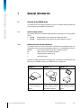
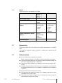
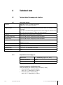
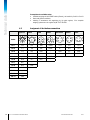
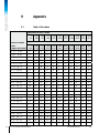
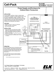
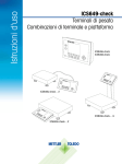
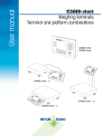
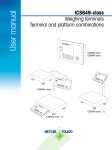
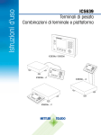
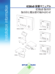
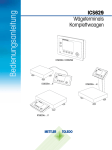
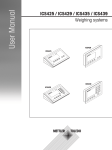
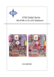
Installation information ICS6x9 Weighing terminals Terminal and platform combinations ICS639 ICS629a / ICS629d ICS639a / ICS639d ICS6x9a-.../c ICS649a / ICS649d ICS6x9a-.../f ICS6x9a-.../t ICS669a / ICS669d Service XXL Congratulations on choosing the quality and precision of METTLER TOLEDO. Proper use according to these instructions and regular calibration and maintenance by our factorytrained service team ensure dependable and accurate operation to protect your investment. Contact us about a ServiceXXL agreement tailored to your needs and budget. We invite you to register your product at www.mt.com/productregistration so we can contact you about enhancements, updates and important notifications concern ing your METTLER TOLEDO product. 2 METTLER TOLEDO Installation information ICS6x9 Order number 22021176A 12/10 Contents 12/10 1 1.1 1.2 1.3 1.4 General information.............................................................................................4 Overview of the ICS6x9 series.................................................................................4 Documentation......................................................................................................5 Safety instructions..................................................................................................5 Tightening torques..................................................................................................6 2 2.1 2.2 2.3 Commissioning....................................................................................................7 Connecting two scales...........................................................................................7 Connecting analog weighing platforms.....................................................................8 Connecting IDNet weighing platforms.....................................................................10 3 3.1 3.2 3.3 Scale configuration............................................................................................11 Calling up the technician menu.............................................................................11 Technician menu operation...................................................................................11 SCALE menu block...............................................................................................12 4 4.1 4.2 4.3 Technical data....................................................................................................19 Technical data of the analog scale interface............................................................19 Assignment of the interface connections.................................................................20 Drilling template..................................................................................................21 5 5.1 Appendix............................................................................................................22 Table of Geo values..............................................................................................22 Order number 22021176A METTLER TOLEDO Installation information ICS6x9 3 General information 1 General information 1.1 Overview of the ICS6x9 series The ICS6x9 series offers weighing terminals to connect a customer weighing platform as well as complete terminal/platform combinations. 1.1.1 ICS6x9 weighing terminals There are two versions of the ICS6x9 weighing terminals, depending on the scale interface SCALE 1: • ICS6x9a weighing terminal with analog scale interface for SCALE 1 • ICS6x9d weighing terminal with digital scale interface (IDNet) for SCALE 1 1.1.2 ICS6x9 terminal and platform combinations The complete name of a terminal and platform combination also indicates the type, size and capacity of the connected analog weighing platform. E.g., ICS629a-QA6/c stands for ICS629a type of weighing terminal and type of weighing interface QA design and size of the weighing platform 6 weighing platform capacity in kg c mechanical design By default the weighing platforms are equipped with a hermetically sealed stainless steel load cell and a readability setting of 2 x 3000 divisions, non-approved. ICS6x9a-.../f ICS6x9a-.../t ICS6x9a-.../c Weighing terminal mounted Fixed cable connection in front of the weighing between weighing terminal platform and weighing platform 4 METTLER TOLEDO Installation information ICS6x9 Weighing terminal and column seamlessly welded together Order number 22021176A 12/10 1.1.3 1.2 Options The following options are available for the ICS6x9: ICS629a, ICS669d, ICS629a-.../f, ICS629a-.../t ICS629a-.../c Built-in storage battery ✔ ✔ Optional scale interface (SCALE 2) • analog • digital – Optional communication interface (COM 2) • • • • RS232 RS422/RS485 Ethernet WLAN • • • • • • Optional communication interface (COM 3) • • • • RS232 RS422/RS485 USB Digital I/O – Desk mounting plate ✔ RS232 RS422/RS485 Ethernet WLAN USB Digital I/O – Documentation The device is supplied with a CD containing the complete documentation on the ICS6x9 series. This Installation information contains information on installing and commissioning the entire series. 1.3 Safety instructions ▲▲ Do not use the device in hazardous environment! Special devices are available in our range of products for hazardous environments. ▲▲ Ensure that the power socket outlet for the device is earthed and easily accessible, so that it can be de-energized quickly in emergencies. ▲▲ Ensure that the supply voltage at the installation site lies within the range of 100 V to 240 V. ▲▲ The safety of the deviced cannot be ensured if it is not operated in accordance with the operating instructions and if it is not installed in accordance with this installation information. ▲▲ Only authorised personnel may open the device. ▲▲ Check the power cable regularly for damage. If it is damaged, disconnect the device immediately from the power supply. ▲▲ Ensure that there is a space of at least 3 cm (1.25") at the rear in order to prevent the power cable from being bent too strongly. 12/10 Order number 22021176A METTLER TOLEDO Installation information ICS6x9 5 General information 1.4 6 Tightening torques ▲▲ For safe operation make sure that all screws and nuts are tightened with the correct tightening torque. M3 M4 M5 M6 M12x1.5 M16x1.5 (nut) M16x1.5 (screw) 0.55 Nm 1.5 Nm 2.5 Nm 5.5 Nm 0.7 Nm 2.5 Nm 3.75 Nm 4.9 Lb-In METTLER TOLEDO Installation information ICS6x9 13.3 Lb-In 22.1 Lb-In 48.7 Lb-In 6.2 Lb-In 22.1 Lb-In 33.2 Lb-In Order number 22021176A 12/10 2 Commissioning 2.1 Connecting two scales Except for the column version the ICS6x9 series provide two scale connections: SCALE 1 and SCALE 2. • Analog and digital scale interfaces can be combined in one terminal. • SCALE 1 and SCALE 2 identify themselves by the scale connection on the mainboard and thus by the scale connection on the housing. • When connecting two scales you do not need to take care of the order. • When connecting only one scale use the SCALE 1 connection. SCALE 1 SCALE 2 SCALE 2 SCALE 1 Verification securing seal 12/10 Rear view Order number 22021176A lnner view METTLER TOLEDO Installation information ICS6x9 7 Commissioning 2.2 Connecting analog weighing platforms Any analog weighing platforms that fulfil the required specifications can be connected to weighing terminals with an analog weighing interface, see Technical data. 2.2.1 Information on the weighing cells Weighing cells with or without SENSE cables ➜➜ In the case of cells without SENSE cables short-circuit the connections +Ex (Excitation) and +Se (Sense) as well as –Ex and –Se at the connector or at the connection terminal. Cells without SENSE cables Cells with SENSE cables 2.2.2 Connection of weighing platforms with several weighing cells Up to four weighing cells can be connected to a weighing terminal in parallel. A junction box is usually used to connect several weighing cells. The sum of the nominal capacities of the individual cells correspond to the total capacity of the weighing system. When entering the scale capacities in the menu, select values in such a way that the individual cells cannot be overloaded. 2.2.3 Preparation of the weighing platform connection cable 1. Strip the cell cable in accordance with the figure. 2. Apply wire end ferrules. 3. Bend the shield. 8 METTLER TOLEDO Installation information ICS6x9 Order number 22021176A 12/10 2.2.4 Connection of an analog weighing platform to the weighing terminal Risk of electric shock ➜➜ Disconnect the weighing terminal from the power supply before beginning installation work. Terminal version 1. Turn over the terminal and loosen the 4 screws. Do not remove the screws. 2. Unscrew the verification screw underneath the verification seal (1). 3. Return the terminal to its normal position and lift off the cover. 4. Lay down the cover in front or leave it hanging down with the plastic hinges. 3a 2a 3b 2b 5. 6. 7. 8. 9. Remove the verification cover (2a/b) by unscrewing the screw. Remove the Digicell PCB (3a/b) by unscrewing the two screws. Unscrew the corresponding cable gland and feed in the weighing platform cable. Fasten the cable gland. For the tightening torque refer to the table on page 6. Connect the weighing platform cable to the terminals on the corresponding Digicell PCB (3a/b). 10.Reassemble Digicell PC and verification cover in reverse order. 11.Close the terminal with 4 screws. For the tightening torque refer to the table on page 6. 12.Screw in the verification screw. 12/10 Order number 22021176A METTLER TOLEDO Installation information ICS6x9 9 Commissioning Colours with METTLER TOLEDO weighing platforms 2.3 Weighing platform EXC– SEN– SIG– Shield SIG+ SEN+ EXC+ PBA226 / PBA430 Black Brown Red – White Blue Green PBA426 / PBA429 Black Grey Red Yellow White Green Blue Connecting IDNet weighing platforms Alternatively to the analog scale connection the weighing terminals can also be equipped with an IDNet scale interface. 1. Set up the weighing platform, refer to the installation information of the weighing platform. 2. Lay the weighing platform cable to the weighing terminal. 3. Ensure that the weighing terminal is switched off. 4. Plug the weighing platform connector into the weighing terminal (SCALE 1 or SCALE 2) and tighten the screw. 10 METTLER TOLEDO Installation information ICS6x9 Order number 22021176A 12/10 3 Scale configuration Scale configuration takes place in the SCALE menu block of the technician menu. 3.1 Calling up the technician menu Access to the technician menu is secured by means of the sealing screw underneath the verification securing seal. 1. Switch on the terminal. 2. Loosen the sealing screw. On verified scales, verification is no longer valid. – or – ➜➜ Enter the technician menu with password . The technician menu is displayed. Verified scales After configuration has been completed, the device has to be recalibrated by an authorised company and a new verification seal has to be attached before the device may be used again as a verified scale. 3.2 Technician menu operation Operation in the technician menu is the same as in the user and supervisor menu, see the corresponding User manual. 12/10 Order number 22021176A METTLER TOLEDO Installation information ICS6x9 11 Scale configuration 3.3 SCALE menu block After the technician menu has been called up, the entire menu is available, also the user and supervisor menu. The following overview shows the SCALE 1 / SCALE 2 menu block, the remaining menu is described in the User manual. The SCALE menu block depends on the connected weighing platform – analog or IDNet. 3.3.1 Overview of the analog SCALE menu block Factory settings are printed in bold in the following overview. Level 1 Level 2 Level 3 See ... Metrology Approval Not Approved, OIML, NTEP page 15 Class Class I, Class II, Class III, Class IIII Ver. interval e = d, e = 10d (Class II only) Display Off, On page 15 Ramp value Serial number page 16 Indicator Scale Scale build Ranges Single range, 2 Multi int., 2 Multi range, 3 Multi int., 3 Multi range Calibrated unit g, kg, oz, lb, t page 16 Capacity 1 Resolution 1 Capacity 2 Resolution 2 Capacity 3 Resolution 3 page 16 GEO value Linearisation 3 Point, 5 Point page 17 Calibration Perform calibration? page 17 page 17 Control Display/Units 12 METTLER TOLEDO Unit 1 g, kg, oz, lb, lb-oz, t Unit 2 g, kg, oz, lb, lb-oz, t Resolution 1200 d ... 175000 d Unit roll Off, On Installation information ICS6x9 User manual Order number 22021176A 12/10 Level 1 Level 2 Level 3 See ... Zero Zero capture -2 to +2%, -2 to +18% page 18 AZM Off, 0.5d, 1d, 2d, 5d, 10d User manual Pushbutton zero Off, On page 18 Center of Zero Off, On Auto tare Off, On Chain tare Off, On A-Clear tare Off, On, 9d Pushbutton tare Off, On Set zero Tare Off, on Filter Vibration Low, Medium, High Process Universal, Dosing Stability Fast, Standard, Precise Function No, Yes Reset 12/10 page 18 User manual Restart MinWeigh User manual User manual User manual Value page 18 Perform reset ? User manual Order number 22021176A METTLER TOLEDO Installation information ICS6x9 13 Scale configuration 3.3.2 Overview of the IDNet SCALE menu block Factory settings are printed in bold in the following overview. Level 1 Level 2 Level 3 See ... Metrology Approval * Not Approved, OIML, NTEP page 15 Class Class I, Class II, Class III, Class IIII Ver. interval * e = d, e = 10d (Class II only) Display Off, On Service mode See Service manual of the connected weighing platform. page 16 Serial number * Display/Units Zero Tare User manual Unit 2 g, kg, oz, lb, lb-oz, t Unit roll Off, On AZM Off, 0.5d, 1d, 2d, 5d, 10d User manual Pushbutton zero Off, On page 18 Center of Zero Off, On Auto tare Off, On Chain tare Off, On A-Clear tare Off, On, 9d Pushbutton tare Off, On User manual page 18 User manual Restart Off, on Filter Vibration Stable, Normal, Unstable Process Universal, Absolute, Finefil Stability ASD = 0, 1, 2, 3, 4, 5 User manual Update 6, 10, 15, 20 UPS User manual MinWeigh Function User manual Reset Off, On MinWeigh value page 18 Perform reset ? User manual * = read only 14 METTLER TOLEDO Installation information ICS6x9 Order number 22021176A 12/10 3.3.3 Description of the SCALE menu block METROLOGY – admissibility for verification Approval * Setting the admissibility for verfication Not approved Scale not verifiable OIML Verify scale to OIML NTEP Verify scale to NTEP, valid for USA Class Setting the verification class, displayed only if approved Class I ... Class IIII Select the verification class Ver. interval * Setting the verification interval, for Class II only e = d Verification interval = display resolution e = 10d Verification interval = 10 x display resolution Display Off No metrological data in the display On Metrology data line enabled Notes • If a scale is verified, various scale settings are no longer available or are only available to a limited extent. Direct access to the menu for service personnel is, furthermore, blocked subsequently for some menu items. • With verification interval e = 10 d the last (not approved) digit is displayed smaller. * read only for IDNet scales RAMP VALUE – querying the value of the A/D converter (analog scales only) Ramp value Ramp 20 Display of the percentage deflection of the analog/digital converter (ramp) Possible values: 0 ... 100 The empty scale has a lower ramp value than the scale with load. Note This value can be used to determine whether the weighing cell operates correctly. Scales with identical weighing cells that function correctly have more or less the same ramp values. The value is dynamic and changes when the load changes. 12/10 Order number 22021176A METTLER TOLEDO Installation information ICS6x9 15 Scale configuration SERIAL NUMBERS * – querying the serial number of terminal and scale Indicator Display or modification of the serial number of the weighing terminal Scale Display or modification of the serial number of the scale Note The serial number should not be changed except, e.g., after a new main PCB has been installed. * read only for IDNet scales SCALE BUILD – entering configuration data (analog scales only) Ranges Defining the scale type Single range Single range scale 2 Multi int. Scale with rough range and 1 shiftable fine range. Automatic switching between the ranges in both directions. 2 Multi range Scale with rough rang and 1 fixed fine range. Automatic switching to the rough range. Return to the fine range at zero pass. 3 Multi int. Scale with rough range and 2 shiftable fine ranges. Automatic switching between the ranges in both directions. 3 Multi range Scale with rough rang and 2 fixed fine ranges. Automatic switching to the rough range. Return to the fine range at zero pass. Calibrated unit Select the basic unit for entering in the service menu Possible units are: g, kg, oz, lb, t Capacity 1/2/3 Enter capacity of the first/second/third range in the calibrated unit Resolution 1/2/3 Select resolution of the first/second/third range in the calibrated unit Note • Capacity 2/3 and Resolution 2/3 are only displayed if they are supported by the scale. • Capacity and resolution are displayed in the following order: Capacity 1, Resolution 1, Capacity 2, Resolution 2, Capacity 3, Resolution 3 • The units g, kg and t are permissible in accordance with verifiable operation to OIML. The units kg and lb are permissible in accordance with verifiable operation to NTEP. GEO VALUE – setting the GEO value (analog scales only) 0 ... 31 16 METTLER TOLEDO Installation information ICS6x9 The Geo value is used to adapt the weighing system to the local gravity conditions. Setting range: 0 ... 31, see table in the Appendix. Order number 22021176A 12/10 LINEARISATION – linearisation with simultaneous calibration (anlaog scales only) A basic calibration must have been carried out at least once for linearisation with simultaneous calibration. 3 Point 3-point linearisation (by default at 0 %, 50 % and 100 % of the full load) 5 Point 5-point linearisation (by default at 0 %, 25 %, 50 %, 75 % and 100 % of the full load) Procedure 1. If existent, apply the preload. 2. Confirm the type of linearisation. The display begins to flash, the scale determines the zero point automatically. The scale next requires the first weight. 3. If appropriate, change the displayed weight value. . 4. Place the displayed weight on the scale and confirm with 5. Repeat steps 3 and 4 for each additional weight. After all the weights have been applied, done is displayed. Note • Determining the zero point can be skipped by pressing existing zero point is used as the reference. • Linearisation/calibration can be cancelled at any time with . In this case the . CALIBRATION – basic calibration (analog scales only) Procedure 1. When Preload is displayed, load the desired preload and confirm with The scale next requests the calibration weight corresponding to the full load. 2. If appropriate, change the displayed weight value. 3. Place the displayed weight on the scale and confirm with . After calibration has been carried out, done is displayed. Note . In this case the existing • Determining the preload can be skipped by pressing zero point is used as reference. • Calibration can be cancelled at any time with . • In order to achieve particularly high precision, carry out calibration under full load. . CONTROL – activating the control mode (analog scales only) Note 12/10 • With control mode enabled, the current weighing result is displayed with high resolution and without weight unit. This allows the scale to be checked, e.g., after calibration and/or linearisation. • To leave the control mode press . Order number 22021176A METTLER TOLEDO Installation information ICS6x9 17 Scale configuration ZERO – Settings for the zero point Zero capture Select the zero capturing range. Possible zero capturing ranges: –2 % to +2 % or –2 % to +18 % Set zero Move the calibration zero point. This is necessary if an auxiliary preload is used or if the preload (e.g. roller conveyor) cannot be used for calibration or if they are outside the zero capturing range. . 1. Apply the preload and confirm with The query Sure ? is displayed. 2. Confirm moving of the zero point with or cancel with . 3. If underload or overload is displayed after the menu has been exited, switch the device off and on again. AZM Setting for the automatic zero compensation mode, refer to the User manual. Pushbutton zero Enabling/disabling manual zeroing using the Center of Zero Switching on/off indication of >0< when zero setting is within the zero capturing range. Note • The zero capturing range limits the nominal capacity of the scale. If the capacity of a weighing cell is to be used to its complete extent, the zero capturing range can be limited to –2 % to +2 %. • The new zero point is not activated until the scale is restarted. • No changes to Zero capture and Set zero should be carried out when the restart function is activated. key. TARE – Settings for the tare function Auto Tare Supervisor menu, refer to the User manual Chain Tare A-Clear Tare Pushbutton Tare Enabling/disabling manual taring using the key. MIN WEIGH – specifying the minimum weighing-in quantity Function Supervisor menu, refer to the User manual Value Entry of the minimum weighing-in quantity in the selected base unit. When the minimum weighing-in quantity is activated, the scale drops below the stored minimum weight. 18 METTLER TOLEDO Installation information ICS6x9 is displayed if the weight on Order number 22021176A 12/10 4 Technical data 4.1 Technical data of the analog scale interface 4.1.1 Analog scale interface Resolution 300,000 points for non-verifiable applications 7,500 points for verifiable applications Weighing ranges up to 3 weighing ranges can be defined in the technician menu, incl. shiftable or fixed fine ranges In the case of verifiable/verified applications the minimum voltage per calibration value (0.5 mV/e) has to be ensured or 7,500 e may not be exceeded. Calibration Basic calibration and calibration during linearisation Zero setting range (key) 2 % of the defined max. useable load, cannot be modified Autozero range 2 % of the defined max. useable load, cannot be modified Activation zero set range –2 % ... 18 % or –2 % ... +2 % referenced to the defined max. useable load, can be selected in the menu Linearity 0.01 % of the defined max. useable load Units g, kg, oz, lb, t, lb-oz Numerical steps 1, 2, 5 x 10n, can be selected in the menu Cell power supply 8.2 V 4.1.2 Requirements for the weighing cell Nominal load 0.1 ... 999,999.9 (g, kg, lb, oz, t, lb-oz) Permissible impedance ≥ 80 W Differential signal –1 mV ... 25 mV (see the following example) Calculation example for the differential signal Data of the weighing cell: Sensitivity 2 mV/V, cell capacity 100 kg • Differential signal for nominal load (60 kg) 2mV/V * 8.2 V * 60 kg/100 kg = 9.84 mV • Differential signal for half load (30 kg) 2mV/V * 8.2 V * 30 kg/100 kg = 4.92 mV 12/10 Order number 22021176A METTLER TOLEDO Installation information ICS6x9 19 Technical data Prerequisites for verifiable scales • Verifiable weighing cell with SENSE cables (6 leads), cell sensitivity 2 mV/V or 3 mV/V • Scale configured as verifiable • Labelling in accordance with regulations by the plant engineer, if the complete weighing system was not supplied by METTLER TOLEDO. 4.2 Digital I/O Assignment of the interface connections RS232 RS422 RS485 USB Device Ethernet Power Socket 20 Pin 1 In 0 CTS TxD+ T/RxD+ +5 V TD+ +12 V Pin 2 In 1 TxD TxD– T/RxD– D– RD+ +12 V Pin 3 In 2 RTS RxD+ – GND TD– GND Pin 4 In 3 RxD +12 V +12 V D+ RD– GND Pin 5 In_GND +12 V GND GND Pin 6 Out 0 +5 V RxD– – Pin 7 Out 1 – Pin 8 Out 2 GND Pin 9 Out 3 Pin 10 Out_GND Pin 11 +12 V Pin 12 GND METTLER TOLEDO Installation information ICS6x9 Order number 22021176A 12/10 4.3 Drilling template Important The drilling template shown below is scaled up. ➜➜ Read the dimensions from the drilling template and copy them to the mounting location. 12/10 Order number 22021176A METTLER TOLEDO Installation information ICS6x9 21 Appendix 5 Appendix 5.1 Table of Geo values Height above sea level in meters 0 325 Northern or southern latitude in degrees and minutes 22 325 650 650 975 975 1300 1300 1625 1625 1950 1950 2275 2275 2600 2600 2925 2915 3250 3250 3575 4260 5330 5330 6400 6400 7460 7460 8530 8530 9600 10660 9600 10660 11730 Height above sea level in feet 0 1060 1060 2130 2130 3200 3200 4260 0° 0' – 5° 46' 5 4 4 3 3 2 2 1 1 0 0 5° 46' – 9° 52' 5 5 4 4 3 3 2 2 1 1 0 9° 52' – 12° 44' 6 5 5 4 4 3 3 2 2 1 1 12° 44' – 15° 6' 6 6 5 5 4 4 3 3 2 2 1 15° 6' – 17° 10' 7 6 6 5 5 4 4 3 3 2 2 17° 10' – 19° 2' 7 7 6 6 5 5 4 4 3 3 2 19° 2' – 20° 45' 8 7 7 6 6 5 5 4 4 3 3 20° 45' – 22° 22' 8 8 7 7 6 6 5 5 4 4 3 22° 22' – 23° 54' 9 8 8 7 7 6 6 5 5 4 4 23° 54' – 25° 21' 9 9 8 8 7 7 6 6 5 5 4 25° 21' – 26° 45' 10 9 9 8 8 7 7 6 6 5 5 26° 45' – 28° 6' 10 10 9 9 8 8 7 7 6 6 5 28° 6' – 29° 25' 11 10 10 9 9 8 8 7 7 6 6 29° 25' – 30° 41' 11 11 10 10 9 9 8 8 7 7 6 30° 41' – 31° 56' 12 11 11 10 10 9 9 8 8 7 7 31° 56' – 33° 9' 12 12 11 11 10 10 9 9 8 8 7 33° 9' – 34° 21' 13 12 12 11 11 10 10 9 9 8 8 34° 21' – 35° 31' 13 13 12 12 11 11 10 10 9 9 8 35° 31' – 36° 41' 14 13 13 12 12 11 11 10 10 9 9 36° 41' – 37° 50' 14 14 13 13 12 12 11 11 10 10 9 37° 50' – 38° 58' 15 14 14 13 13 12 12 11 11 10 10 38° 58' – 40° 5' 15 15 14 14 13 13 12 12 11 11 10 40° 5' – 41° 12' 16 15 15 14 14 13 13 12 12 11 11 41° 12' – 42° 19' 16 16 15 15 14 14 13 13 12 12 11 METTLER TOLEDO Installation information ICS6x9 Order number 22021176A 12/10 Height above sea level in meters 0 325 Northern or southern latitude in degrees and minutes 325 650 650 975 975 1300 1300 1625 1625 1950 1950 2275 2275 2600 2600 2925 2915 3250 3250 3575 Height above sea level in feet 0 1060 1060 2130 2130 3200 3200 4260 4260 5330 5330 6400 6400 7460 7460 8530 8530 9600 10660 9600 10660 11730 41° 19' – 43° 26' 17 16 16 15 15 14 14 13 13 12 12 43° 26' – 44° 32' 17 17 16 16 15 15 14 14 13 13 12 44° 32' – 45° 38' 18 17 17 16 16 15 15 14 14 13 13 45° 38' – 46° 45' 18 18 17 17 16 16 15 15 14 14 13 46° 45' – 47° 51' 19 18 18 17 17 16 16 15 15 14 14 47° 51' – 48° 58' 19 19 18 18 17 17 16 16 15 15 14 48° 58' – 50° 6' 20 19 19 18 18 17 17 16 16 15 15 50° 6' – 51° 13' 20 20 19 19 18 18 17 17 16 16 15 51° 13' – 52° 22' 21 20 20 19 19 18 18 17 17 16 16 52° 22' – 53° 31' 21 21 20 20 19 19 18 18 17 17 16 53° 31' – 54° 41' 22 21 21 20 20 19 19 18 18 17 17 54° 41' – 55° 52' 22 22 21 21 20 20 19 19 18 18 17 55° 52' – 57° 4' 23 22 22 21 21 20 20 19 19 18 18 57° 7' – 58° 17' 23 23 22 22 21 21 20 20 19 19 18 58° 17' – 59° 32' 24 23 23 22 22 21 21 20 20 19 19 59° 32' – 60° 49' 24 24 23 23 22 22 21 21 20 20 19 60° 49' – 62° 9' 25 24 24 23 23 22 22 21 21 20 20 62° 9' – 63° 30' 25 25 24 24 23 23 22 22 21 21 20 63° 30' – 64° 55' 26 25 25 24 24 23 23 22 22 21 21 64° 55' – 66° 24' 26 26 25 25 24 24 23 23 22 22 21 66° 24' – 67° 57' 27 26 26 25 25 24 24 23 23 22 22 67° 57' – 69° 35' 27 27 26 26 25 25 24 24 23 23 22 69° 35' – 71° 21' 28 27 27 26 26 25 25 24 24 23 23 71° 21' – 73° 16' 28 28 27 27 26 26 25 25 24 24 23 73° 16' – 75° 24' 29 28 28 27 27 26 26 25 25 24 24 75° 24' – 77° 52' 29 29 28 28 27 27 26 26 25 25 24 77° 52' – 80° 56' 30 29 29 28 28 27 27 26 26 25 25 80° 56' – 85° 45' 30 30 29 29 28 28 27 27 26 26 25 85° 45' – 90° 0' 31 30 30 29 29 28 28 27 27 26 26 12/10 Order number 22021176A METTLER TOLEDO Installation information ICS6x9 23 To protect your METTLER TOLEDO product’s future: METTLER TOLEDO Service XXL assures the quality, measuring accuracy and preservation of value of all METTLER TOLEDO products for years to come. Please send for full details about our attractive terms of service. Thank you. www.mt.com/service For more information Mettler-Toledo (Albstadt) GmbH D-72458 Albstadt Tel. + 49 7431-14 0 Fax + 49 7431-14 232 Subject to technical changes © 12/2010 Mettler-Toledo (Albstadt) GmbH Printed in Germany Order number 22021176A *22021176A* * 2 2 0 2 1 1 7 6 A *