1
Table of Contents
INTRODUCTION
ABOUT QUICKLINK ....................................................................................................................
Vehicles Covered ..................................................................................................................
The QUICKLINK™ Device ....................................................................................................
The QUICKLINK™ App .........................................................................................................
COMPUTER ENGINE CONTROLS ............................................................................................
The Introduction of Electronic Engine Controls .....................................................................
The Basic Engine Computer Control System ........................................................................
On-Board Diagnostics - First Generation (OBD1) .................................................................
On-Board Diagnostics - Second Generation (OBD2) ............................................................
OBD2 Terminology ................................................................................................................
DIAGNOSTIC TROUBLE CODES (DTCs) ..................................................................................
DTCs and MIL Status ............................................................................................................
OBD2 MONITORS ......................................................................................................................
Continuous Monitors ..............................................................................................................
Non-Continuous Monitors ......................................................................................................
OBD2 Reference Table .........................................................................................................
BEFORE YOU BEGIN .................................................................................................................
VEHICLE SERVICE MANUALS .................................................................................................
ABOUT REPAIRSOLUTIONS® ..................................................................................................
1
1
2
2
2
2
3
4
5
6
7
9
10
11
11
18
19
19
20
FOR iOS DEVICES
GETTING STARTED
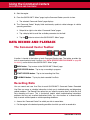
DOWNLOADING THE QUICKLINK™ APP .................................................................................
LAUNCHING THE QUICKLINK™ APP .......................................................................................
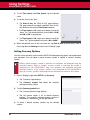
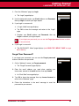
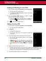
Creating an Account ..............................................................................................................
Confirming Your Account .......................................................................................................
Logging In ..............................................................................................................................
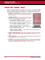
USING THE “MENU” PAGE ........................................................................................................
27
27
28
28
28
30
MANAGING VEHICLES
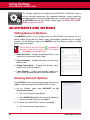
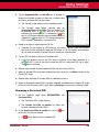
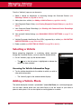
SETTING UP YOUR VEHICLE ...................................................................................................
Entering the Vehicle Identification Number (VIN) ..................................................................
USING THE “VEHICLES” PAGE .................................................................................................
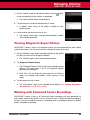
Selecting a Vehicle ................................................................................................................
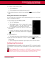
Adding a Vehicle Photo .........................................................................................................
Viewing Diagnostic Report History ........................................................................................
Working with Command Center Recordings ..........................................................................
MANAGING VEHICLE SETTINGS ..............................................................................................
Editing the Vehicle Description ..............................................................................................
Viewing and Editing General Vehicle Settings ......................................................................
QUICKLINK™
31
31
31
32
32
33
34
36
36
37
i
Table of Contents
Viewing and Editing OBD-II Settings .....................................................................................
Viewing and Editing Advanced Settings ................................................................................
VALIDATIING SUPPORTED PIDS .............................................................................................
DELETING A VEHICLE ...............................................................................................................
38
39
41
42
GENERATING DIAGNOSTIC REPORTS
INSTALLING AND PAIRING THE QUICKLINK™ DEVICE .........................................................
Installing the QUICKLINK™ Device ......................................................................................
Pairing the QUICKLINK™ Device ..........................................................................................
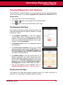
CREATING A REPORT ...............................................................................................................
Connecting the App to the Device .........................................................................................
Viewing Diagnostics and Solutions ........................................................................................
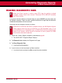
ERASING DIAGNOSTIC DATA ..................................................................................................
43
43
43
44
44
45
47
WORKING WITH COMMAND CENTERS
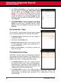
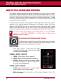
ABOUT THE COMMAND CENTERS ..........................................................................................
Performance Command Center .............................................................................................
Fuel Economy Command Center ..........................................................................................
Engine Command Center ......................................................................................................
Towing Command Center ......................................................................................................
Using the Command Centers ................................................................................................
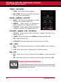
DATA RECORD AND PLAYBACK ..............................................................................................
The Command Center Toolbar ..............................................................................................
Recording Data ......................................................................................................................
Data Playback .......................................................................................................................
48
48
49
49
50
51
52
52
52
53
USING SETTINGS
ADJUSTMENTS AND SETTINGS ..............................................................................................
Setting General Options ........................................................................................................
Viewing Account Options .......................................................................................................
Configuring Connection Options ............................................................................................
Configuring Setup Options ....................................................................................................
Configuring Parameters .........................................................................................................
Using About Options ..............................................................................................................
CONTACTING TECHNICAL SERVICES ....................................................................................
Reporting a Problem ..............................................................................................................
Using Console Options ..........................................................................................................
54
54
54
55
55
58
60
60
60
61
FOR ANDROID DEVICES
GETTING STARTED
DOWNLOADING THE QUICKLINK™ APP .................................................................................
LAUNCHING THE QUICKLINK™ APP .......................................................................................
Creating an Account ..............................................................................................................
ii
63
63
64
QUICKLINK™
Table of Contents
Confirming Your Account .......................................................................................................
Logging In ..............................................................................................................................
USING THE “MENU” PAGE ........................................................................................................
64
64
66
MANAGING VEHICLES
SETTING UP YOUR VEHICLE ...................................................................................................
Entering the Vehicle Identification Number (VIN) ..................................................................
USING THE “VEHICLES” PAGE .................................................................................................
Selecting a Vehicle ................................................................................................................
Adding a Vehicle Photo .........................................................................................................
Viewing Diagnostic Report History ........................................................................................
Working with Command Center Recordings ..........................................................................
MANAGING VEHICLE SETTINGS ..............................................................................................
Editing the Vehicle Description ..............................................................................................
Viewing and Editing General Vehicle Settings ......................................................................
Viewing and Editing OBD-II Settings .....................................................................................
Viewing and Editing Advanced Settings ................................................................................
VALIDATING SUPPORTED PIDS ..............................................................................................
DELETING A VEHICLE ...............................................................................................................
67
67
67
68
68
69
69
71
71
72
73
73
76
76
GENERATING DIAGNOSTIC REPORTS
INSTALLING AND PAIRING THE QUICKLINK™ DEVICE .........................................................
Installing the QUICKLINK™ Device ......................................................................................
Pairing the QUICKLINK™ Device ..........................................................................................
Connecting the App to the Device .........................................................................................
CREATING A REPORT ...............................................................................................................
Viewing Diagnostics and Solutions ........................................................................................
ERASING DIAGNOSTIC DATA ..................................................................................................
77
77
77
78
78
79
81
WORKING WITH COMMAND CENTERS
ABOUT THE COMMAND CENTERS ..........................................................................................
Performance Command Center .............................................................................................
Fuel Economy Command Center ..........................................................................................
Engine Command Center ......................................................................................................
Towing Command Center ......................................................................................................
Using the Command Centers ................................................................................................
DATA RECORD AND PLAYBACK ..............................................................................................
The Command Center Toolbar ..............................................................................................
Recording Data ......................................................................................................................
Data Playback .......................................................................................................................
82
82
83
83
84
85
86
86
86
87
USING SETTINGS
ADJUSTMENTS AND SETTINGS ..............................................................................................
Setting General Options ........................................................................................................
QUICKLINK™
88
88
iii
Table of Contents
Viewing Account Options .......................................................................................................
Configuring Connection Options ............................................................................................
Configuring Setup Options ....................................................................................................
Configuring Parameters .........................................................................................................
Using About Options ..............................................................................................................
CONTACTING TECHNICAL SERVICES ....................................................................................
Reporting a Problem ..............................................................................................................
Viewing the Console ..............................................................................................................
88
89
89
91
94
94
94
95
WARRANTY AND SERVICING
LIMITED ONE YEAR WARRANTY .............................................................................................
SERVICE PROCEDURES ..........................................................................................................
iv
97
97
QUICKLINK™
Introduction
ABOUT QUICKLINK™
ABOUT QUICKLINK™
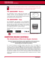
QUICKLINK™ is a “wireless” system that lets you connect to your
vehicle’s on-board computer using your favorite “smart” device
(phone or tablet). You can use QUICKLINK™ to help in diagnosing
CHECK ENGINE problems, check for road trip readiness, verify
mechanic estimates, find ways to improve your fuel economy, and
much more. The QUICKLINK™ system consists of the
QUICKLINK™ Device and the associated QUICKLINK™ App
(available for both iOS and Android devices). The QUICKLINK™
system is designed to work on all OBD2 compliant vehicles. All
1996 and newer vehicles (cars and light trucks) sold in the United
States are OBD2 compliant.
Federal law requires that all 1996 and newer cars and light trucks sold in the United
States must be OBD2 compliant; this includes all Domestic, Asian and European
vehicles.
Vehicles Covered
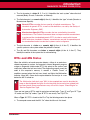
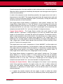
Some 1994 and 1995 vehicles are OBD2 compliant. To find out if a 1994 or 1995 vehicle is
OBD2 compliant, check the following:
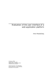
VEHICLE EMISSION CONTROL INFORMATION
ENGINE FAMILY
DISPLACEMENT
VEHICLE
EFN2.6YBT2BA
2.6L
OBD II
CERTIFIED
THIS VEHICLE CONFORMS TO U.S. EPA AND STATE
MANUFACTURER OF CALIFORNIA REGULATIONS APPLICABLE TO
1999 MODEL YEAR NEW TLEV PASSENGER CARS.
1. The Vehicle Emissions Control Information (VECI) Label. This label is located
under the hood or by the radiator of most
vehicles. If the vehicle is OBD2 compliant,
the label will state “OBD II Certified.”
REFER TO SERVICE MANUAL FOR ADDITIONAL INFORMATION
TUNE-UP CONDITIONS: NORMAL OPERATING ENGINE TEMPERATURE,
ACCESSORIES OFF, COOLING FAN OFF, TRANSMISSION IN NEUTRAL
EXHAUST EMISSIONS STANDARDS
CERTIFICATION
IN-USE
SPARK PLUG
TYPE NGK BPRE-11
GAP: 1.1MM
OBD II
CERTIFIED
STANDARD CATEGORY
TLEV
TLEV INTERMEDIATE
CATALYST
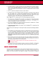
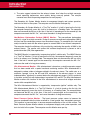
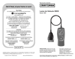
2. Government Regulations require that all
OBD2 compliant vehicles have a “common”
sixteen-pin Data Link Connector (DLC).
1 2 3 4 5 6 7 8
9 10 11 12 13 14 15 16
Data Link Connector (DLC)
Location
The 16-pin DLC is usually located under the
instrument panel (dash), within 12 inches (300
mm) of center of the panel, on the driver’s side
of most vehicles. It should be easily accessible
and visible from a kneeling position outside the
vehicle with the door open.
QUICKLINK™
BEHIND
ASHTRAY
LEFT CORNER
OF DASH
NEAR
CENTER
OF DASH
1
Introduction
COMPUTER ENGINE CONTROLS
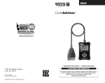
On some Asian and European vehicles the DLC is located behind the “ashtray” (the
ashtray must be removed to access it) or on the far left corner of the dash. If the DLC
cannot be located, consult the vehicle’s service manual for the location.
The QUICKLINK™ Device
The QUICKLINK™ Device provides the link between your
vehicle’s computer and the QUICKLINK™ App on your
“smart” phone or table. The QUICKLINK™ Device connects to
your vehicle’s Data Link Connector (DLC).
The QUICKLINK™ App
The QUICKLINK™ App connects to the QUICKLINK™
Device wirelessly, through Bluetooth. The App provides you
with the tools you need to add vehicles to your account,
generate diagnostic reports for your vehicle, and view Live
Data using the QUICKLINK™ Command Centers.
The QUICKLINK™ App is available for both iOS and Android
devices.
You must have an active Wi-Fi connection to use the QUICKLINK™ system.
COMPUTER ENGINE CONTROLS
The Introduction of Electronic Engine Controls
Electronic Computer Control Systems make it possible for vehicle manufacturers
to comply with the tougher emissions and fuel efficiency standards
mandated by State and Federal Governments.
As a result of increased air pollution (smog) in large cities, such as Los Angeles, the
California Air Resources Board (CARB) and the Environmental Protection Agency (EPA) set
new regulations and air pollution standards to deal with the problem. To further complicate
matters, the energy crisis of the early 1970s caused a sharp increase in fuel prices over a
short period. As a result, vehicle manufacturers were not only required to comply with the
new emissions standards, they also had to make their vehicles more fuel-efficient. Most
vehicles were required to meet a miles-per-gallon (MPG) standard set by the U.S. Federal
Government.
2
QUICKLINK™
Introduction
COMPUTER ENGINE CONTROLS
Precise fuel delivery and spark timing are needed to reduce vehicle emissions. Mechanical
engine controls in use at the time (such as ignition points, mechanical spark advance and the
carburetor) responded too slowly to driving conditions to properly control fuel delivery and
spark timing. This made it difficult for vehicle manufacturers to meet the new standards.
A new Engine Control System had to be designed and integrated with the engine controls to
meet the stricter standards. The new system had to:
Respond instantly to supply the proper mixture of air and fuel for any driving condition
(idle, cruising, low-speed driving, high-speed driving, etc.).
Calculate instantly the best time to “ignite” the air/fuel mixture for maximum engine
efficiency.
Perform both these tasks without affecting vehicle performance or fuel economy.
Vehicle Computer Control Systems can perform millions of calculations each second. This
makes them an ideal substitute for the slower mechanical engine controls. By switching from
mechanical to electronic engine controls, vehicle manufacturers are able to control fuel
delivery and spark timing more precisely. Some newer Computer Control Systems also
provide control over other vehicle functions, such as transmission, brakes, charging, body,
and suspension systems.
The Basic Engine Computer Control System
The Computer Control System consists of an on-board computer and several
related control devices (sensors, switches, and actuators).
The on-board computer is the heart of the Computer Control System. The computer contains
several programs with preset reference values for air/fuel ratio, spark or ignition timing,
injector pulse width, engine speed, etc. Separate values are provided for various driving
conditions, such as idle, low speed driving, high-speed driving, low load, or high load. The
preset reference values represent the ideal air/fuel mixture, spark timing, transmission gear
selection, etc., for any driving condition. These values are programmed by the vehicle
manufacturer, and are specific to each vehicle model.
Most on-board computers are located inside the vehicle behind the dashboard, under the
passenger’s or driver’s seat, or behind the right kick panel. However, some manufacturers
may still position it in the engine compartment.
Vehicle sensors, switches, and actuators are located throughout the engine, and are
connected by electrical wiring to the on-board computer. These devices include oxygen
sensors, coolant temperature sensors, throttle position sensors, fuel injectors, etc. Sensors
and switches are input devices. They provide signals representing current engine operating
conditions to the computer. Actuators are output devices. They perform actions in response
to commands received from the computer.
QUICKLINK™
3
Introduction
COMPUTER ENGINE CONTROLS
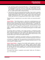
TYPICAL COMPUTER
CONTROL SYSTEM
OUTPUT DEVICES
Fuel Injectors
Idle Air Control
EGR Valve
Ignition Module
On-Board
Computer
INPUT DEVICES
Coolant Temperature Sensor
Throttle Position Sensor
Fuel Injectors
INPUT DEVICES
Oxygen Sensors
The on-board computer receives information inputs from sensors and switches located
throughout the engine. These devices monitor critical engine conditions such as coolant
temperature, engine speed, engine load, throttle position, air/fuel ratio etc.
The computer compares the values received from these sensors with its preset reference
values, and makes corrective actions as needed so that the sensor values always match the
preset reference values for the current driving condition. The computer makes adjustments
by commanding other devices such as the fuel injectors, idle air control, EGR valve or
Ignition Module to perform these actions.
Vehicle operating conditions are constantly changing. The computer continuously makes
adjustments or corrections (especially to the air/fuel mixture and spark timing) to keep all the
engine systems operating within the preset reference values.
On-Board Diagnostics - First Generation (OBD1)
With the exception of some 1994 and 1995 vehicles, most vehicles from 1982 to 1995
are equipped with some type of first generation On-Board Diagnostics.
Beginning in 1988, California’s Air Resources Board (CARB), and later the Environmental
Protection Agency (EPA) required vehicle manufacturers to include a self-diagnostic program
in their on-board computers. The program would be capable of identifying emissions-related
faults in a system. The first generation of Onboard Diagnostics came to be known as OBD1.
OBD1 is a set of self-testing and diagnostic instructions programmed into the vehicle’s onboard computer. The programs are specifically designed to detect failures in the sensors,
actuators, switches and wiring of the various vehicle emissions-related systems. If the
computer detects a failure in any of these components or systems, it lights an indicator on
the dashboard to alert the driver. The indicator lights only when an emissions-related
problem is detected.
4
QUICKLINK™
Introduction
COMPUTER ENGINE CONTROLS
The computer also assigns a numeric code for each specific problem that it detects, and
stores these codes in its memory for later retrieval. These codes can be retrieved from the
computer’s memory with the use of a “Code Reader” or a “Diagnostic Tool.”
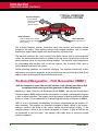
On-Board Diagnostics - Second Generation
(OBD2)
The OBD2 System is an enhancement of the OBD1 System.
In addition to performing all the functions of the OBD1 System, the OBD2 System has been
enhanced with new Diagnostic Programs. These programs closely monitor the functions of
various emissions-related components and systems (as well as other systems) and make
this information readily available (with the proper equipment) to the technician for evaluation.
The California Air Resources Board (CARB) conducted studies on OBD1 equipped vehicles.
The information that was gathered from these studies showed the following:
A large number of vehicles had deteriorating or degraded emissions-related components.
These components were causing an increase in emissions.
Because OBD1 systems only detect failed components, the degraded components were
not setting codes.
Some emissions problems related to degraded components only occur when the vehicle
is being driven under a load. The emission checks being conducted at the time were not
performed under simulated driving conditions. As a result, a significant number of
vehicles with degraded components were passing Emissions Tests.
Codes, code definitions, diagnostic connectors, communication protocols and emissions
terminology were different for each manufacturer. This caused confusion for the
technicians working on different make and model vehicles.
To address the problems made evident by this study, CARB and the EPA passed new laws
and standardization requirements. These laws required that vehicle manufacturers to equip
their new vehicles with devices capable of meeting all of the new emissions standards and
regulations. It was also decided that an enhanced on-board diagnostic system, capable of
addressing all of these problems, was needed. This new system is known as “On-Board
Diagnostics Generation Two (OBD2).” The primary objective of the OBD2 system is to
comply with the latest regulations and emissions standards established by CARB and the
EPA.
The Main Objectives of the OBD2 System are:
To detect degraded and/or failed emissions-related components or systems that could
cause tailpipe emissions to exceed by 1.5 times the Federal Test Procedure (FTP)
standard.
QUICKLINK™
5
Introduction
COMPUTER ENGINE CONTROLS
To expand emissions-related system monitoring. This includes a set of computer run
diagnostics called Monitors. Monitors perform diagnostics and testing to verify that all
emissions-related components and/or systems are operating correctly and within the
manufacturer’s specifications.
To use a standardized Diagnostic Link Connector (DLC) in all vehicles. (Before OBD2,
DLCs were of different shapes and sizes.)
To standardize the code numbers, code definitions and language used to describe faults.
(Before OBD2, each vehicle manufacturer used their own code numbers, code definitions
and language to describe the same faults.)
To expand the operation of the Malfunction Indicator Lamp (MIL).
To standardize communication procedures and protocols between the diagnostic
equipment (Diagnostic Tools, Code Readers, etc.) and the vehicle’s on-board computer.
OBD2 Terminology
The following terms and their definitions are related to OBD2 systems. Read and reference
this list as needed to aid in the understanding of OBD2 systems.
Powertrain Control Module (PCM) - The PCM is the OBD2 accepted term for the
vehicle’s “on-board computer.” In addition to controlling the engine management and
emissions systems, the PCM also participates in controlling the powertrain (transmission)
operation. Most PCMs also have the ability to communicate with other computers on the
vehicle (ABS, ride control, body, etc.).
Monitor - Monitors are “diagnostic routines” programmed into the PCM. The PCM utilizes
these programs to run diagnostic tests, and to monitor operation of the vehicle’s
emissions-related components or systems to ensure they are operating correctly and
within the vehicle’s manufacturer specifications. Currently, up to fifteen Monitors are used
in OBD2 systems. Additional Monitors will be added as the OBD2 system is further
developed.
Not all vehicles support all fifteen Monitors.
Enabling Criteria - Each Monitor is designed to test and monitor the operation of a
specific part of the vehicle’s emissions system (EGR system, oxygen sensor, catalytic
converter, etc.). A specific set of “conditions” or “driving procedures” must be met before
the computer can command a Monitor to run tests on its related system. These
“conditions” are known as “Enabling Criteria.” The requirements and procedures vary for
each Monitor. Some Monitors only require the ignition key to be turned “On” for them to
run and complete their diagnostic testing. Others may require a set of complex
procedures, such as, starting the vehicle when cold, bringing it to operating temperature,
and driving the vehicle under specific conditions before the Monitor can run and complete
its diagnostic testing.
6
QUICKLINK™
Introduction
DIAGNOSTIC TROUBLE CODES (DTCs)
Monitor Has/Has Not Run - The terms “Monitor has run” or “Monitor has not run” are
used throughout this manual. “Monitor has run” means the PCM has commanded a
particular Monitor to perform the required diagnostic testing on a system to ensure the
system is operating correctly (within factory specifications). The term “Monitor has not
run” means the PCM has not yet commanded a particular Monitor to perform diagnostic
testing on its associated part of the emissions system.
Trip - A Trip for a particular Monitor requires that the vehicle is being driven in such a
way that all the required “Enabling Criteria” for the Monitor to run and complete its
diagnostic testing are met. The “Trip Drive Cycle” for a particular Monitor begins when the
ignition key is turned “On.” It is successfully completed when all the “Enabling Criteria” for
the Monitor to run and complete its diagnostic testing are met by the time the ignition key
is turned “Off.” Since each of the fifteen monitors is designed to run diagnostics and
testing on a different part of the engine or emissions system, the “Trip Drive Cycle”
needed for each individual Monitor to run and complete varies.
OBD2 Drive Cycle - An OBD2 Drive Cycle is an extended set of driving procedures that
takes into consideration the various types of driving conditions encountered in real life.
These conditions may include starting the vehicle when it is cold, driving the vehicle at a
steady speed (cruising), accelerating, etc. An OBD2 Drive Cycle begins when the ignition
key is turned “On” (when cold) and ends when the vehicle has been driven in such a way
as to have all the “Enabling Criteria” met for all its applicable Monitors. Only those trips
that provide the Enabling Criteria for all Monitors applicable to the vehicle to run and
complete their individual diagnostic tests qualify as an OBD2 Drive Cycle. OBD2 Drive
Cycle requirements vary from one model of vehicle to another. Vehicle manufacturers set
these procedures. Consult your vehicle’s service manual for OBD2 Drive Cycle
procedures.
Do not confuse a “Trip” Drive Cycle with an OBD2 Drive Cycle. A “Trip” Drive
Cycle provides the “Enabling Criteria” for one specific Monitor to run and complete
its diagnostic testing. An OBD2 Drive Cycle must meet the “Enabling Criteria” for
all Monitors on a particular vehicle to run and complete their diagnostic testing.
Warm-up Cycle - Vehicle operation after an engine off period where engine temperature
rises at least 40°F (22°C) from its temperature before starting, and reaches at least
160°F (70°C). The PCM uses warm-up cycles as a counter to automatically erase a
specific code and related data from its memory. When no faults related to the original
problem are detected within a specified number of warm-up cycles, the code is erased
automatically.
DIAGNOSTIC TROUBLE CODES (DTCs)
Diagnostic Trouble Codes (DTCs) are codes that identify a specific problem area.
Diagnostic Trouble Codes (DTCs) are meant to guide you to the proper service procedure in
the vehicle’s service manual. DO NOT replace parts based only on DTCs without first
consulting the vehicle’s service manual for proper testing procedures for that particular
system, circuit or component.
QUICKLINK™
7
Introduction
DIAGNOSTIC TROUBLE CODES (DTCs)
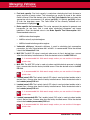
DTCs are alphanumeric codes that are used to identify a problem that is present in any of the
systems that are monitored by the on-board computer (PCM). Each trouble code has an
assigned message that identifies the circuit, component or system area where the problem
was found.
OBD2 diagnostic trouble codes are made up of five characters.
OBD2 DTC EXAMPLE
P0201 - Injector Circuit Malfunction, Cylinder 1
B
C
P
U
-
Body
Chassis
Powertrain
Network
P0201
0 - Generic
1 - Manufacturer Specific
2 - Generic ("P" Codes) and Manufacturer
Specific ("B", "C" and "U" Codes)
3 - Includes both Generic and Manufacturer
Specific Codes
Identifies the system where the problem is
located. "P" Code systems are listed below.
"B", "C" and "U" Code systems will vary.
0 - Fuel and Air Metering; Auxiliary Emission
Controls
1 - Fuel and Air Metering
2 - Fuel and Air Metering (injector circuit
malfunction only)
3 - Ignition System or Misfire
4 - Auxiliary Emission Control System
5 - Vehicle Speed Control and Idle Control
System
6 - Computer Output Circuits
7 - Transmission
8 - Transmission
9 - Transmission
A - Hybrid Propulsion
B - Hybrid Propulsion
C - Hybrid Propulsion
Identifies what section of the system
is malfunctioning
8
QUICKLINK™
Introduction
DIAGNOSTIC TROUBLE CODES (DTCs)
The 1st character is a letter (B, C, P or U). It identifies the “main system” where the fault
occurred (Body, Chassis, Powertrain, or Network).
The 2nd character is a numeric digit (0 thru 3). It identifies the “type” of code (Generic or
Manufacturer-Specific).
Generic DTCs are codes that are used by all vehicle manufacturers. The
standards for generic DTCs, as well as their definitions, are set by the Society of
Automotive Engineers (SAE).
Manufacturer-Specific DTCs are codes that are controlled by the vehicle
manufacturers. The Federal Government does not require vehicle manufacturers
to go beyond the standardized generic DTCs in order to comply with the new
OBD2 emissions standards. However, manufacturers are free to expand beyond
the standardized codes to make their systems easier to diagnose.
The 3rd character is a letter or a numeric digit (0 thru 9, A thru F). It identifies the
specific system or sub-system where the problem is located.
The 4th and 5th characters are letters or numeric digits (0 thru 9, A thru F). They
identify the section of the system that is malfunctioning.
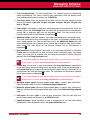
DTCs and MIL Status
When the vehicle’s on-board computer detects a failure in an emissionsrelated component or system, the computer’s internal diagnostic program
assigns a diagnostic trouble code (DTC) that points to the system (and
subsystem) where the fault was found. The diagnostic program saves the
code in the computer’s memory. It records a “Freeze Frame” of
conditions present when the fault was found, and lights the Malfunction
Indicator Lamp (MIL). Some faults require detection for two trips in a row
before the MIL is turned on.
The “Malfunction Indicator Lamp” (MIL) is the accepted term used to describe the
lamp on the dashboard that lights to warn the driver that an emissions-related fault
has been found. Some manufacturers may still call this lamp a “Check Engine” or
“Service Engine Soon” light.
There are two types of DTCs used for emissions-related faults: Type “A” and Type “B.” Type
“A” codes are “One-Trip” codes; Type “B” DTCs are usually Two-Trip DTCs.
When a Type “A” DTC is found on the First Trip, the following events take place:
The computer commands the MIL “On” when the failure is first found.
QUICKLINK™
9
Introduction
OBD2 MONITORS
If the failure causes a severe misfire that may cause damage to the catalytic converter,
the MIL “flashes” once per second. The MIL continues to flash as long as the condition
exists. If the condition that caused the MIL to flash is no longer present, the MIL will light
“steady” On.
A DTC is saved in the computer’s memory for later retrieval.
A “Freeze Frame” of the conditions present in the engine or emissions system when the
MIL was ordered “On” is saved in the computer’s memory for later retrieval. This
information shows fuel system status (closed loop or open loop), engine load, coolant
temperature, fuel trim value, MAP vacuum, engine RPM and DTC priority.
When a Type “B” DTC is found on the First Trip, the following events take place:
The computer sets a Pending DTC, but the MIL is not ordered “On.” “Freeze Frame” data
may or may not be saved at this time depending on manufacturer. The Pending DTC is
saved in the computer’s memory for later retrieval.
If the failure is found on the second consecutive trip, the MIL is ordered “On.” “Freeze
Frame” data is saved in the computer’s memory.
If the failure is not found on the second Trip, the Pending DTC is erased from the
computer’s memory.
The MIL will stay lit for both Type “A” and Type “B” codes until one of the following conditions
occurs:
If the conditions that caused the MIL to light are no longer present for the next three trips
in a row, the computer automatically turns the MIL “Off” if no other emissions-related
faults are present. However, the DTCs remain in the computer’s memory as a history
code for 40 warm-up cycles (80 warm-up cycles for fuel and misfire faults). The DTCs are
automatically erased if the fault that caused them to be set is not detected again during
that period.
Misfire and fuel system faults require three trips with “similar conditions” before the MIL is
turned “Off.” These are trips where the engine load, RPM and temperature are similar to
the conditions present when the fault was first found.
After the MIL has been turned off, DTCs and Freeze Frame data stay in the
computer’s memory.
Erasing the DTCs from the computer’s memory can also turn off the MIL. If a Diagnostic
Tool or Scan Tool is used to erase the codes, Freeze Frame data will also be erased.
OBD2 MONITORS
To ensure the correct operation of the various emissions-related components and systems, a
diagnostic program was developed and installed in the vehicle’s on-board computer. The
program has several procedures and diagnostic strategies. Each procedure or diagnostic
10
QUICKLINK™
Introduction
OBD2 MONITORS
strategy is made to monitor the operation of, and run diagnostic tests on, a specific
emissions-related component or system. These tests ensure the system is running correctly
and is within the manufacturer’s specifications. On OBD2 systems, these procedures and
diagnostic strategies are called “Monitors.”
Currently, fifteen Monitors are supported by OBD2 systems. Additional monitors may be
added as a result of Government regulations as the OBD2 system grows and matures. Not
all vehicles support all fifteen Monitors. Additionally, some Monitors are supported by “spark
ignition” vehicles only, while others are supported by “compression ignition” vehicles only.
Monitor operation is either “Continuous” or “Non-Continuous,” depending on the specific
monitor.
Continuous Monitors
Three of these Monitors are designed to constantly monitor their associated components
and/or systems for proper operation. Continuous Monitors run constantly when the engine is
running. The Continuous Monitors are:
Comprehensive Component Monitor (CCM)
Misfire Monitor
Fuel System Monitor
Non-Continuous Monitors
The other twelve Monitors are “non-continuous” Monitors. “Non-continuous” Monitors perform
and complete their testing once per trip. The “non-continuous” Monitors are:
Oxygen Sensor Monitor
Oxygen Sensor Heater Monitor
Catalyst Monitor
Heated Catalyst Monitor
EGR System Monitor
EVAP System Monitor
Secondary Air System Monitor
The following Monitors became standard beginning in 2010. The majority of
vehicles produced before this time will not support these Monitors.
NMHC Monitor
QUICKLINK™
11
Introduction
OBD2 MONITORS
NOx Adsorber Monitor
Boost Pressure System Monitor
Exhaust Gas Sensor Monitor
PM Filter Monitor
The following provides a brief explanation of the function of each Monitor:
Comprehensive Component Monitor (CCM) - This Monitor continuously checks all inputs
and outputs from sensors, actuators, switches and other devices that provide a signal to the
computer. The Monitor checks for shorts, opens, out of range value, functionality and
“rationality.”
Rationality: Each input signal is compared against all other inputs and against
information in the computer’s memory to see if it makes sense under the current
operating conditions. Example: The signal from the throttle position sensor indicates
the vehicle is in a wide-open throttle condition, but the vehicle is really at idle, and the
idle condition is confirmed by the signals from all other sensors. Based on the input
data, the computer determines that the signal from the throttle position sensor is not
rational (does not make sense when compared to the other inputs). In this case, the
signal would fail the rationality test.
The CCM is supported by both “spark ignition” vehicles and “compression ignition” vehicles.
The CCM may be either a “One-Trip” or a “Two-Trip” Monitor, depending on the component.
Fuel System Monitor - This Monitor uses a Fuel System Correction program, called Fuel
Trim, inside the on-board computer. Fuel Trim is a set of positive and negative values that
represent adding or subtracting fuel from the engine. This program is used to correct for a
lean (too much air/not enough fuel) or rich (too much fuel/not enough air) air-fuel mixture.
The program is designed to add or subtract fuel, as needed, up to a certain percent. If the
correction needed is too large and exceeds the time and percent allowed by the program, a
fault is indicated by the computer.
The Fuel System Monitor is supported by both “spark ignition” vehicles and “compression
ignition” vehicles. The Fuel System Monitor may be a “One-Trip” or “Two-Trip” Monitor,
depending on the severity of the problem.
Misfire Monitor - This Monitor continuously checks for engine misfires. A misfire occurs
when the air-fuel mixture in the cylinder does not ignite. The misfire Monitor uses changes in
crankshaft speed to sense an engine misfire. When a cylinder misfires, it no longer
contributes to the speed of the engine, and engine speed decreases each time the affected
cylinder(s) misfire. The misfire Monitor is designed to sense engine speed fluctuations and
determine from which cylinder(s) the misfire is coming, as well as how bad the misfire is.
There are three types of engine misfires, Types 1, 2, and 3.
12
QUICKLINK™
Introduction
OBD2 MONITORS
Type 1 and Type 3 misfires are two-trip monitor faults. If a fault is sensed on the first trip,
the computer temporarily saves the fault in its memory as a Pending Code. The MIL is
not commanded on at this time. If the fault is found again on the second trip, under
similar conditions of engine speed, load and temperature, the computer commands the
MIL “On,” and the code is saved in its long term memory.
Type 2 misfires are the most severe type of misfire. When a Type 2 misfire is sensed on
the first trip, the computer commands the MIL to light when the misfire is sensed. If the
computer determines that a Type 2 misfire is severe , and may cause catalytic converter
damage, it commands the MIL to “flash” once per second as soon as the misfire is
sensed. When the misfire is no longer present, the MIL reverts to steady “On” condition.
The Misfire Monitor is supported by both “spark ignition” vehicles and “compression ignition”
vehicles.
Catalyst Monitor - The catalytic converter is a device that is installed downstream of the
exhaust manifold. It helps to oxidize (burn) the unburned fuel (hydrocarbons) and partially
burned fuel (carbon monoxide) left over from the combustion process. To accomplish this,
heat and catalyst materials inside the converter react with the exhaust gases to burn the
remaining fuel. Some materials inside the catalytic converter also have the ability to store
oxygen, and release it as needed to oxidize hydrocarbons and carbon monoxide. In the
process, it reduces vehicle emissions by converting the polluting gases into carbon dioxide
and water.
The computer checks the efficiency of the catalytic converter by monitoring the oxygen
sensors used by the system. One sensor is located before (upstream of) the converter; the
other is located after (downstream of) the converter. If the catalytic converter loses its ability
to store oxygen, the downstream sensor signal voltage becomes almost the same as the
upstream sensor signal. In this case, the monitor fails the test.
The Catalyst Monitor is supported by “spark ignition” vehicles only. The Catalyst Monitor is a
“Two-Trip” Monitor. If a fault is found on the first trip, the computer temporarily saves the fault
in its memory as a Pending Code. The computer does not command the MIL on at this time.
If the fault is sensed again on the second trip, the computer commands the MIL “On” and
saves the code in its long-term memory.
Heated Catalyst Monitor - Operation of the “heated” catalytic converter is similar to the
catalytic converter. The main difference is that a heater is added to bring the catalytic
converter to its operating temperature more quickly. This helps reduce emissions by reducing
the converter’s down time when the engine is cold. The Heated Catalyst Monitor performs
the same diagnostic tests as the catalyst Monitor, and also tests the catalytic converter’s
heater for proper operation.
The Heated Catalyst Monitor is supported by “spark ignition” vehicles only. This Monitor is
also a “Two-Trip” Monitor.
QUICKLINK™
13
Introduction
OBD2 MONITORS
Exhaust Gas Recirculation (EGR) Monitor - The Exhaust Gas Recirculation (EGR) system
helps reduce the formation of Oxides of Nitrogen during combustion. Temperatures above
2500°F cause nitrogen and oxygen to combine and form Oxides of Nitrogen in the
combustion chamber. To reduce the formation of Oxides of Nitrogen, combustion
temperatures must be kept below 2500°F. The EGR system recirculates small amounts of
exhaust gas back into the intake manifold, where it is mixed with the incoming air/fuel
mixture. This reduces combustion temperatures by up to 500°F. The computer determines
when, for how long, and how much exhaust gas is recirculated back to the intake manifold.
The EGR Monitor performs EGR system function tests at preset times during vehicle
operation.
The EGR Monitor is supported by both “spark ignition” vehicles and “compression ignition”
vehicles. The EGR Monitor is a “Two-Trip” Monitor. If a fault is found on the first trip, the
computer temporarily saves the fault in its memory as a Pending Code. The computer does
not command the MIL on at this time. If the fault is sensed again on the second trip, the
computer commands the MIL “On,” and saves the code in its long-term memory.
Evaporative System (EVAP) Monitor - OBD2 vehicles are equipped with a fuel Evaporative
system (EVAP) that helps prevent fuel vapors from evaporating into the air. The EVAP
system carries fumes from the fuel tank to the engine where they are burned during
combustion. The EVAP system may consist of a charcoal canister, fuel tank cap, purge
solenoid, vent solenoid, flow monitor, leak detector and connecting tubes, lines and hoses.
Fumes are carried from the fuel tank to the charcoal canister by hoses or tubes. The fumes
are stored in the charcoal canister. The computer controls the flow of fuel vapors from the
charcoal canister to the engine via a purge solenoid. The computer energizes or deenergizes the purge solenoid (depending on solenoid design). The purge solenoid opens a
valve to allow engine vacuum to draw the fuel vapors from the canister into the engine where
the vapors are burned. The EVAP Monitor checks for proper fuel vapor flow to the engine,
and pressurizes the system to test for leaks. The computer runs this Monitor once per trip.
The EVAP Monitor is supported by “spark ignition” vehicles only. The EVAP Monitor is a
“Two-Trip” Monitor. If a fault is found on the first trip, the computer temporarily saves the fault
in its memory as a Pending Code. The computer does not command the MIL on at this time.
If the fault is sensed again on the second trip, the PCM commands the MIL “On,” and saves
the code in its long-term memory.
Oxygen Sensor Heater Monitor - The Oxygen Sensor Heater Monitor tests the operation of
the oxygen sensor’s heater. There are two modes of operation on a computer-controlled
vehicle: “open-loop” and “closed-loop.” The vehicle operates in open-loop when the engine is
cold, before it reaches normal operating temperature. The vehicle also goes to open-loop
mode at other times, such as heavy load and full throttle conditions. When the vehicle is
running in open-loop, the oxygen sensor signal is ignored by the computer for air/fuel mixture
corrections. Engine efficiency during open-loop operation is very low, and results in the
production of more vehicle emissions.
14
QUICKLINK™
Introduction
OBD2 MONITORS
Closed-loop operation is the best condition for both vehicle emissions and vehicle operation.
When the vehicle is operating in closed-loop, the computer uses the oxygen sensor signal for
air/fuel mixture corrections.
In order for the computer to enter closed-loop operation, the oxygen sensor must reach a
temperature of at least 600°F. The oxygen sensor heater helps the oxygen sensor reach and
maintain its minimum operating temperature (600°F) more quickly, to bring the vehicle into
closed-loop operation as soon as possible.
The Oxygen Sensor Heater Monitor is supported by “spark ignition” vehicles only. The
Oxygen Sensor Heater Monitor is a “Two-Trip” Monitor. If a fault is found on the first trip, the
computer temporarily saves the fault in its memory as a Pending Code. The computer does
not command the MIL on at this time. If the fault is sensed again on the second trip, the
computer commands the MIL “On,” and saves the code in its long-term memory.
Oxygen Sensor Monitor - The Oxygen Sensor monitors how much oxygen is in the
vehicle’s exhaust. It generates a varying voltage of up to one volt, based on how much
oxygen is in the exhaust gas, and sends the signal to the computer. The computer uses this
signal to make corrections to the air/fuel mixture. If the exhaust gas has a large amount of
oxygen (a lean air/fuel mixture), the oxygen sensor generates a “low” voltage signal. If the
exhaust gas has very little oxygen (a rich mixture condition), the oxygen sensor generates a
“high” voltage signal. A 450mV signal indicates the most efficient, and least polluting, air/fuel
ratio of 14.7 parts of air to one part of fuel.
The oxygen sensor must reach a temperature of at least 600-650°F, and the engine must
reach normal operating temperature, for the computer to enter into closed-loop operation.
The oxygen sensor only functions when the computer is in closed-loop. A properly operating
oxygen sensor reacts quickly to any change in oxygen content in the exhaust stream. A
faulty oxygen sensor reacts slowly, or its voltage signal is weak or missing.
The Oxygen Sensor Monitor is supported by “spark ignition” vehicles only. The Oxygen
Sensor Monitor is a “Two-Trip” monitor. If a fault is found on the first trip, the computer
temporarily saves the fault in its memory as a Pending Code. The computer does not
command the MIL on at this time. If the fault is sensed again on the second trip, the
computer commands the MIL “On,” and saves the code in its long-term memory.
Secondary Air System Monitor - When a cold engine is first started, it runs in open-loop
mode. During open-loop operation, the engine usually runs rich. A vehicle running rich
wastes fuel and creates increased emissions, such as carbon monoxide and some
hydrocarbons. A Secondary Air System injects air into the exhaust stream to aid catalytic
converter operation:
It supplies the catalytic converter with the oxygen it needs to oxidize the carbon
monoxide and hydrocarbons left over from the combustion process during engine warmup.
QUICKLINK™
15
Introduction
OBD2 MONITORS
The extra oxygen injected into the exhaust stream also helps the catalytic converter
reach operating temperature more quickly during warm-up periods. The catalytic
converter must heat to operating temperature to work properly.
The Secondary Air System Monitor checks for component integrity and system operation,
and tests for faults in the system. The computer runs this Monitor once per trip.
The Secondary Air System Monitor is a “Two-Trip” monitor. If a fault is found on the first trip,
the computer temporarily saves this fault in its memory as a Pending Code. The computer
does not command the MIL on at this time. If the fault is sensed again on the second trip, the
computer commands the MIL “On,” and saves the code in its long-term memory.
Non-Methane Hydrocarbon Catalyst (NMHC) Monitor - The non-methane hydrocarbon
catalyst is a type of catalytic converter. It helps to remove non-methane hydrocarbons (NMH)
left over from the combustion process from the exhaust stream. To accomplish this, heat and
catalyst materials react with the exhaust gases to convert NMH to less harmful compounds.
The computer checks the efficiency of the catalyst by monitoring the quantity of NMH in the
exhaust stream. The monitor also verifies that sufficient temperature is present to aid in
particulate matter (PM) filter regeneration.
The NMHC Monitor is supported by “compression ignition” vehicles only. The NMHC Monitor
is a “Two-Trip” Monitor. If a fault is found on the first trip, the computer temporarily saves the
fault in its memory as a Pending Code. The computer does not command the MIL on at this
time. If the fault is sensed again on the second trip, the computer commands the MIL “On,”
and saves the code in its long-term memory.
NOx Aftertreatment Monitor - NOx aftertreatment is based on a catalytic converter support
that has been coated with a special washcoat containing zeolites. NOx Aftertreatment is
designed to reduce oxides of nitrogen emitted in the exhaust stream. The zeolite acts as a
molecular "sponge" to trap the NO and NO2 molecules in the exhaust stream. In some
implementations, injection of a reactant before the aftertreatment purges it. NO2 in particular
is unstable, and will join with hydrocarbons to produce H2O and N2. The NOx Aftertreatment
Monitor monitors the function of the NOx aftertreatment to ensure that tailpipe emissions
remain within acceptable limits.
The NOx Aftertreatment Monitor is supported by “compression ignition” vehicles only. The
NOx Aftertreatment Monitor is a “Two-Trip” Monitor. If a fault is found on the first trip, the
computer temporarily saves the fault in its memory as a Pending Code. The computer does
not command the MIL on at this time. If the fault is sensed again on the second trip, the
computer commands the MIL “On,” and saves the code in its long-term memory.
Boost Pressure System Monitor - The boost pressure system serves to increase the
pressure produced inside the intake manifold to a level greater than atmospheric pressure.
This increase in pressure helps to ensure compete combustion of the air-fuel mixture. The
Boost Pressure System Monitor checks for component integrity and system operation, and
tests for faults in the system. The computer runs this Monitor once per trip.
16
QUICKLINK™
Introduction
OBD2 MONITORS
The Boost Pressure System Monitor is supported by “compression ignition” vehicles only.
The Boost Pressure System Monitor is a “Two-Trip” Monitor. If a fault is found on the first trip,
the computer temporarily saves the fault in its memory as a Pending Code. The computer
does not command the MIL on at this time. If the fault is sensed again on the second trip, the
computer commands the MIL “On,” and saves the code in its long-term memory.
Exhaust Gas Sensor Monitor - The exhaust gas sensor is used by a number of
systems/monitors to determine the content of the exhaust stream. The computer checks for
component integrity, system operation, and tests for faults in the system, as well as feedback
faults that may affect other emission control systems.
The Exhaust Gas Sensor Monitor is supported by “compression ignition” vehicles only. The
Exhaust Gas Sensor Monitor is a “Two-Trip” Monitor. If a fault is found on the first trip, the
computer temporarily saves the fault in its memory as a Pending Code. The computer does
not command the MIL on at this time. If the fault is sensed again on the second trip, the
computer commands the MIL “On,” and saves the code in its long-term memory.
PM Filter Monitor - The particulate matter (PM) filter removes particulate matter from the
exhaust stream by filtration. The filter has a honeycomb structure similar to a catalyst
substrate, but with the channels blocked at alternate ends. This forces the exhaust gas to
flow through the walls between the channels, filtering the particulate matter out. The filters
are self-cleaning by periodic modification of the exhaust gas concentration in order to burn
off the trapped particles (oxidizing the particles to form CO2 and water). The computer
monitors the efficiency of the filter in trapping particulate matter, as well as the ability of the
filter to regenerate (self-clean).
The PM Filter Monitor is supported by “compression ignition” vehicles only. The PM Filter
Monitor is a “Two-Trip” Monitor. If a fault is found on the first trip, the computer temporarily
saves the fault in its memory as a Pending Code. The computer does not command the MIL
on at this time. If the fault is sensed again on the second trip, the computer commands the
MIL “On,” and saves the code in its long-term memory.
QUICKLINK™
17
Introduction
OBD2 MONITORS
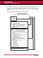
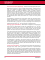
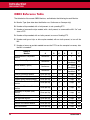
OBD2 Reference Table
The table below lists current OBD2 Monitors, and indicates the following for each Monitor:
A. Monitor Type (how often does the Monitor run; Continuous or Once per trip)
B. Number of trips needed, with a fault present, to set a pending DTC
C. Number of consecutive trips needed, with a fault present, to command the MIL “On” and
store a DTC
D. Number of trips needed, with no faults present, to erase a Pending DTC
E. Number and type of trips or drive cycles needed, with no faults present, to turn off the
MIL
F. Number of warm-up periods needed to erase the DTC from the computer’s memory after
the MIL is turned off
Name of
Monitor
Comprehensive Component
Monitor
Misfire Monitor (Type 1 and 3)
Misfire Monitor (Type 2)
Fuel System Monitor
18
A
B
C
D
E
F
Continuous
1
2
1
3
40
Continuous
1
2
1
3 - similar
conditions
80
3 - similar
conditions
80
Continuous
1
Continuous
1
1 or 2
1
3 - similar
conditions
80
Catalytic Converter Monitor
Once per trip
1
2
1
3 trips
40
Oxygen Sensor Monitor
Once per trip
1
2
1
3 trips
40
Oxygen Sensor Heater Monitor
Once per trip
1
2
1
3 trips
40
Exhaust Gas Recirculation (EGR)
Monitor
Once per trip
1
2
1
3 trips
40
Evaporative Emissions Controls
Monitor
Once per trip
1
2
1
3 trips
40
Secondary Air System (AIR)
Monitor
Once per trip
1
2
1
3 trips
40
NMHC Monitor
Once per trip
1
2
1
3 trips
40
Nox Adsorber Monitor
Once per trip
1
2
1
3 trips
40
Boost Pressure System Monitor
Once per trip
1
2
1
3 trips
40
Exhaust Gas Sensor Monitor
Once per trip
1
2
1
3 trips
40
PM Filter Monitor
Once per trip
1
2
1
3 trips
40
QUICKLINK™
Introduction
BEFORE YOU BEGIN – VEHICLE SERVICE MANUALS
BEFORE YOU BEGIN
Mechanical problems such as low oil level or damaged hoses, wiring or electrical connectors
can cause poor engine performance and may also cause a fault code to set. Fix any known
mechanical problems before performing any test. See your vehicle’s service manual or a
mechanic for more information. Check the following areas before starting any test:
Check the engine oil, power steering fluid, transmission fluid (if applicable), engine
coolant and other fluids for proper levels. Top off low fluid levels if needed.
Make sure the air filter is clean and in good condition. Make sure all air filter ducts are
properly connected. Check the air filter ducts for holes, rips or cracks.
Make sure all engine belts are in good condition. Check for cracked, torn, brittle, loose or
missing belts.
Make sure mechanical linkages to engine sensors (throttle, gearshift position,
transmission, etc.) are secure and properly connected. See your vehicle’s service manual
for locations.
Check all rubber hoses (radiator) and steel hoses (vacuum/fuel) for leaks, cracks,
blockage or other damage. Make sure all hoses are routed and connected properly.
Make sure all spark plugs are clean and in good condition. Check for damaged, loose,
disconnected or missing spark plug wires.
Make sure the battery terminals are clean and tight. Check for corrosion or broken
connections. Check for proper battery and charging system voltages.
Check all electrical wiring and harnesses for proper connection. Make sure wire
insulation is in good condition, and there are no bare wires.
Make sure the engine is mechanically sound. If needed, perform a compression check,
engine vacuum check, timing check (if applicable), etc.
VEHICLE SERVICE MANUALS
Always refer to the manufacturer’s service manual for your vehicle before performing any test
or repair procedures. Contact your local car dealership, auto parts store or bookstore for
availability of these manuals. The following companies publish valuable repair manuals:
Haynes Publications, 861 Lawrence Drive, Newbury Park, California 91320,
Phone: 800-442-9637, Web: www.haynes.com
Mitchell 1, 14145 Danielson Street, Poway, California 92064,
Phone: 888-724-6742, Web: www.m1products.com
Motor Publications, 5600 Crooks Road, Suite 200, Troy, Michigan 48098,
Phone: 800-426-6867, Web: www.motor.com
QUICKLINK™
19
Introduction
ABOUT REPAIRSOLUTIONS
FACTORY SOURCES
Ford, GM, Chrysler, Honda, Isuzu, Hyundai and Subaru Service Manuals
Helm Inc., 14310 Hamilton Avenue, Highland Park, Michigan 48203,
Phone: 800-782-4356, Web: www.helminc.com
ABOUT REPAIRSOLUTIONS®
RepairSolutions® is a web-based service that provides you with the tools and information
you need to quickly and accurately diagnose and repair today’s vehicles. At the core of
RepairSolutions® is an extensive knowledge database, developed by compiling and
analyzing years worth of “real world” vehicle service data. RepairSolutions® builds on
manufacturer-recommended diagnostic and repair information by providing verified, vehiclespecific fixes supplied by ASE technicians across the country. QUICKLINK™ uses the
RepairSolutions database to generate diagnostic reports for your vehicle. The basic
RepairSolutions® account is free, and is available immediately upon purchase of the
QUICKLINK™ system. Certain “value added” premium information is available on demand at
nominal charge or through “premium” subscription.
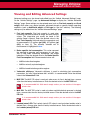
The RepairSolutions® Diagnostic Report
The RepairSolutions® Diagnostic Report provides you with detailed information for
diagnosing and repairing vehicle issues. The Diagnostic Report gives you the following
information:
Some features are available only with a “premium” subscription to RepairSolutions®.
Summary – The Summary page shows the current status of your vehicle’s emissions,
engine/transmission, supplemental restraint (airbag) and anti-lock brake systems, and
provides a summary of the issues associated with your vehicle.
Verified Fixes – The Verified Fixes page lists the most likely repair(s) needed by your
vehicle based on the DTCs retrieved. It includes cost estimates for the repair(s) based on
your geographic location, provides access to detailed instructions for performing the
repair(s), and includes links to supplemental information (including articles and videos)
related to the affected component or system.
Diagnostic Data – The Diagnostic Data page provides detailed information related to
the DTCs retrieved from your vehicle’s computer. It includes descriptions of the retrieved
DTCs including the conditions under which each DTC was set, the probable causes for
the issue and recommendations for verifying the problem. You can also view Freeze
Frame data for the “priority” DTC (the DTC that caused the MIL to illuminate) and current
I/M Monitor status.
20
QUICKLINK™
Introduction
ABOUT REPAIRSOLUTIONS
TSBs / Recalls - Even with the exhaustive testing a vehicle undergoes before being
made available to the public, some issues are discovered only under “real world” driving
conditions. Depending on the severity of the problem, the vehicle manufacturer may
issue a Technical Service Bulletin describing the problem, and providing the procedures
necessary to correct it. For safety related problems, vehicle manufacturers are required
to issue vehicle recalls to correct the problem. The TSBs / Recalls page lists three main
categories for issues related to your vehicle: Factory Technical Service Bulletins (TSBs),
Factory Recalls, and Government-mandated NHTSA Safety Recalls. This information can
help you identify a problem before it occurs, and ensure your vehicle meets Federal
safety standards.
Maintenance - The Maintenance page provides information to help keep your vehicle in
top running condition. The page uses your vehicle’s year, make, model and current
mileage to provide a list of manufacturer-recommended periodic maintenance procedures
that should be performed during its next scheduled service. These maintenance items
are highly recommended and should be per-formed to best protect against premature
failure. The page also includes additional recommended service procedures based on
analysis of component failures reported by the RepairSolutions® network of technicians
for vehicles of your make, model and mileage. All procedures include estimates of cost
and level of difficulty.
Warranty – Warranties are the vehicle manufacturer's promise to cover certain
repair/replacement costs for a specific amount of time or until the vehicle has been driven
for a specific number of miles. The Warranty page provides an estimation of the current
state of your vehicle’s warranties (whether they are active, expired, and/or transferable).
This information is intended for reference only. It is based on manufacturer published
data available at the time the data was gathered and may not fully reflect your actual
warranty coverage.
Predicted Repairs – Solving a problem before it becomes a problem can reduce out-ofpocket cost and minimize personal inconvenience. Through detailed analysis of historical
repair information supplied by technician across the country, RepairSolutions® is able to
provide highly accurate predictions of potential service and repair requirements based on
your vehicle’s year, make, model and mileage. The Predicted Repairs page provides a
list of predicted repairs for your vehicle over the next 12 months. The predicted repairs
are weighted by probability (high, moderate or low) and include cost estimates.
Vehicle History Reports – Thinking of buying a vehicle? RepairSolutions® provides
“one click” access for the purchase of a vehicle history report.
The Portal Page
The Portal page gives you an overview of your RepairSolutions® account. It shows your
Account Status and provides access to the reports you have most recently generated using a
registered Innova tool.
QUICKLINK™
21
Introduction
ABOUT REPAIRSOLUTIONS
Innova Account
The Innova Account section lets you manage the vehicles and tools you’ve registered with
your account and manage your personal information.
My Garage – Your RepairSolutions® account can be used for multiple vehicles. The My
Garage page you add, view and edit vehicles for your account.
Report History – Each report you create through RepairSolutions® is retained through
the lifetime of your membership, giving you an overview of the health of your vehicles.
The Report History page lets you browse a list of all reports created through
RepairSolutions® for all vehicles registered to your account, and view any report listed.
You can also search the list based on the criteria (report #, VIN, etc.) you specify.
Registered Devices – You can register all of your Innova tools with your
RepairSolutions® account. The Registered Devices page shows all the tools registered
to your account along with the date on which the device was activated.
Order History – You can purchase “premium” access to RepairSolutions® on a monthly
or annual basis. The Order History page lists all subscriptions you’ve purchased for your
account.
Profile and Reset Password – These pages let you update and maintain your personal
account information and change the password you use to log in to RepairSolutions®.
Tools
The RepairSolutions® Tools section provides access to several databases offering
maintenance and repair instruction, “tech tips,” safety information and general reference
data.
How-To Videos – With the complexity of today’s vehicles, repair tasks can seem
daunting even to the seasoned do-it-yourselfer. RepairSolutions® offers a rich selection
of How-To Videos that provide step-by-step instruction for a variety of tasks, including
general maintenance, diagnosis and troubleshooting, and detailed repair information. The
“basic” membership provides access to a selection of available videos, while the
“premium” subscription allows access to the complete video library.
Recalls – Even with the exhaustive testing a vehicle undergoes before being made
available to the public, some issues are discovered only under “real world” driving
conditions. When an issue that affects personal safety is found, or if a vehicle does not
meet Federal safety standards, the Government mandates that the vehicle manufacturer
issue a “safety recall.” Safety recalls are official notices that describe known vehicle
issues as well as the related safety concerns. Repairs performed to address a safety
recall are provided free of cost by the vehicle manufacturer’s dealership. The Recalls
database helps you ensure the safety of your vehicle. You can search for safety recalls
by entering a vehicle’s year, make and model.
22
QUICKLINK™
Introduction
ABOUT REPAIRSOLUTIONS
DTC Library – Diagnostic Trouble Codes (DTCs) are the starting point for identifying,
troubleshooting and repairing vehicle issues. The DTC Library contains definitions for
“generic” and “manufacturer-specific” OBD2 DTCs as well as OBD1 codes. Currently, the
database provides code definitions for 43 different vehicle makes. Select the desired
make and enter the DTC to retrieve the specific definition for your vehicle. Because
OBD2 is an evolving system, the DTC Library is continuously updated to include
additional “manufacturer-specific” definitions as the system matures.
DLC Locator – The key to unlocking the wealth of information available through OBD2 is
the Data Link Connector (DLC), the doorway to your vehicle’s computer. The DLC
Locator is a comprehensive database of DLC locations for all OBD2-certified vehicles.
Simply enter a Vehicle Identification Number (VIN), or select the desired year, make and
model, and the DLC Locator will return a description and photo illustration of the DLC
location.
Tech Tips – Updated quarterly, RepairSolutions® Tech Tips are designed to provide
basic solutions to everyday vehicle issues, explain how to perform much needed
maintenance, and provide basic information on how to take care of your vehicle. All Tech
Tips are prepared, reviewed and approved with the support of ASE Certified Technicians.
Shop Locator – Whether you want to purchase parts to make a repair yourself or find a
local repair shop, the Shop Locator will return a list facilities near your location based on
the Zip Code you provide.
QUICKLINK™
23
Introduction
PRELIMINARY VEHICLE DIAGNOSTIC WORKSHEET
PRELIMINARY VEHICLE DIAGNOSTIC WORKSHEET
The purpose of this form is to help you gather preliminary information on your vehicle before you
retrieve codes. By having a complete account of your vehicle's current problem(s), you will be able
to systematically pinpoint the problem(s) by comparing your answers to the fault codes you retrieve.
You can also provide this information to your mechanic to assist in diagnosis and help avoid costly
and unnecessary repairs. It is important for you to complete this form to help you and/or your
mechanic have a clear understanding of your vehicle's problems.
NAME:
DATE:
VIN*:
YEAR:
MAKE:
MODEL:
ENGINE SIZE:
VEHICLE MILEAGE:
*VIN: Vehicle Identification Number, found at the base of the windshield on a metallic plate, or at the
driver door latch area (consult your vehicle owner's manual for location).
TRANSMISSION:
Automatic
Manual
Please check all applicable items in each category.
DESCRIBE THE PROBLEM:
24
QUICKLINK™
Introduction
PRELIMINARY VEHICLE DIAGNOSTIC WORKSHEET
WHEN DID YOU FIRST NOTICE THE PROBLEM:
Just Started
Started Last Month
Started Last Week
Other:
LIST ANY REPAIRS DONE IN THE PAST SIX MONTHS:
PROBLEMS STARTING
No symptoms
Cranks, but will not start
Will not crank
Starts, but takes a long time
ENGINE QUITS OR STALLS
No symptoms
Right after vehicle comes to a stop
Right after starting
While idling
When shifting into gear
During acceleration
During steady-speed driving
When parking
IDLING CONDITIONS
No symptoms
Is sometimes too fast or too slow
Is too slow at all times
Is rough or uneven
Is too fast
Fluctuates up and down
RUNNING CONDITIONS
No symptoms
Backfires
Runs rough
Misfires or cuts out
Lacks power
Engine knocks, pings or rattles
Bucks and jerks
Surges
Poor fuel economy
Dieseling or run-on
Hesitates or stumbles on accelerations
AUTOMATIC TRANSMISSION PROBLEMS (if applicable)
No symptoms
Vehicle does not move when in gear
Shifts too early or too late
Jerks or bucks
Changes gear incorrectly
QUICKLINK™
25
Introduction
PRELIMINARY VEHICLE DIAGNOSTIC WORKSHEET
PROBLEM OCCURS
Morning
Afternoon
Anytime
ENGINE TEMPERATURE WHEN PROBLEM OCCURS
Cold
Warm
Hot
DRIVING CONDITIONS WHEN PROBLEM OCCURS
Short - less than 2 miles
2 - 10 miles
Long - more than 10 miles
Stop and go
While turning
While braking
At gear engagement
With A/C operating
With headlights on
During acceleration
Mostly driving downhill
Mostly driving uphill
Mostly driving level
Mostly driving curvy roads
Mostly driving rough roads
DRIVING HABITS
Drive less than 10 miles per day
Drive 10 to 50 miles per day
Drive more than 50 miles per day
Mostly city driving
Highway
Park vehicle inside
Park vehicle outside
GASOLINE USED
87 Octane
89 Octane
91 Octane
More than 91 Octane
WEATHER CONDITIONS WHEN PROBLEM OCCURS
32 - 55° F (0 - 13° C)
Below freezing (32° F / 0° C)
Above 55° F (13° C)
CHECK ENGINE LIGHT / DASH WARNING LIGHT
Sometimes ON
Always ON
Never ON
PECULIAR SMELLS
"Hot"
Sulfur ("rotten egg")
Burning rubber
Gasoline
Burning oil
Electrical
STRANGE NOISES
Rattle
Knock
26
Squeak
Other
QUICKLINK™
Getting Started
DOWNLOADING THE QUICKLINK™ APP - LAUNCHING THE QUICKLINK™ APP
DOWNLOADING THE QUICKLINK™ APP
The QUICKLINK™ App is available for free download from
the App Store. You MUST have an iTunes account to
download the QUICKLINK™ App from the App Store.
1. Tap the App Store icon to access the App Store.
2. Enter “QUICKLINK” in the search box, then tap the
to locate the QUICKLINK™ App.
icon
3. Tap the FREE button to download the QUICKLINK™ App
to your tablet or phone.
When the download is complete, the INSTALL button
displays.
4. Tap the INSTALL button to install the QUICKLINK™ App on your phone or tablet.
When the installation is complete, the OPEN button displays.
5. Tap the OPEN button to launch the QUICKLINK™ App (see LAUNCHING THE QUICKLINK™ APP on page 27 for details).
If you do not with to launch the QUICKLINK™ App at this time, exit the App Store.
You can launch QUICKLINK™ at any time by tapping the QUICKLINK™ icon or your
phone or tablet.
When you open the QUICKLINK™ App, the “Innova Account” page displays. You
MUST have an account on Innova.com to use the QUICKLINK™ system to obtain
diagnostic information for your vehicle. The account is FREE of charge.
LAUNCHING THE QUICKLINK™ APP
The first time you access the Innova Account page, the “Use Current Location”
popup displays. Tap OK to allow QUICKLINK™ to use your current location. If you do
not wish QUICKLINK™ to use your current location, tap Don’t Allow.
If you already have an account on Innova.com, tap Login to log into QUICKLINK (see
Logging In on page 28 for details).
If you don’t have an account on Innova.com, tap Create account to create a free account
(see Creating an Account on page 28 for details).
QUICKLINK™ for iOS
27
Getting Started
LAUNCHING THE QUICKLINK™ APP
Creating an Account
1. From the Innova Account page, tap Create account.
The “Create account” page displays.
2. Enter your name in the First name and Last name fields.
3. Enter your email address in the Email field.
4. Enter your home Zip Code in the Zip field. This information is optional.
5. Enter a password for your account in the Password and
Confirm password fields.
Enter the password in exactly the same way in both
the Password and Confirm password fields.
6. When all required information has been entered, tap Submit.
If you omit a required field or do not enter your password the same way in both
the Password and Confirm password fields, an “Error” message displays. Tap
OK to close the message and return to the “Create account” page. Enter the
required information then resubmit the form.
The Terms and Conditions popup displays.
7. Review the Terms and Conditions then tap Next to continue.
The End User License Agreement (EULA) popup displays.
8. Review the End User License Agreement then tap Yes.
The QICKLINK “Menu” page displays.
Confirming Your Account
When you register you Innova.com account, the system auto-generates an email to the email
address you provided during registration. BE SURE to confirm your account using the
instructions provided in the confirmation email before using the QUICKLINK™ system.
Logging In
Following your account registration, and each time you launch the QUICKLINK™ App, the
QUICKLINK™ “Welcome” page displays. You must log into your Innova.com account before
you can use the QUICKLINK™ system.
28
QUICKLINK™ for iOS
Getting Started
LAUNCHING THE QUICKLINK™ APP
1. From the “Welcome” page, tap Login.
The “Login” page displays.
2. Use the keyboard to enter your Email address and
Password, then tap Login to submit your login request.
3. If your login is unsuccessful:
A “Login failed” message displays.
Tap OK to close the message and return to the “Login”
page.
Re-enter your Email address and Password, then tap
Login to resubmit your login request.
If you forget your password, you can use the Forgot password feature to obtain
a new password.
4. If your login is successful:
The QUICKLINK™ “Menu” page displays (see USING THE “MENU” PAGE on page
30 for details).
Forgot Your Password?
If you forget your password, you can use the Forgot password feature to obtain a new
password.
1. On the “Welcome” screen, tap Forgot password.
The “Forgot Password” page displays.
2. Enter the email address you used when creating your
Innova.com account in the email text box, then tap
Submit.
An “Email Sent” message displays.
3. Tap OK to close the message then tap Innova Account
to return to the “Welcome” page.
4. Follow the instructions in the email message to reset the
password for your account.
QUICKLINK™ for iOS
29
Getting Started
USING THE “MENU” PAGE
USING THE “MENU” PAGE
When you log into QUICKLINK™ (see Logging In on page 28 for details), the “Menu” page
displays. The “Menu” page gives you access to all the features and functions available
through the QUICKLINK™ App. The following options are available from the “Menu” page:
DIAGNOSTICS / SOLUTIONS - lets you generate a
diagnostic report for your vehicle (see Generating
Diagnostic Reports on page 20 for details)
COMMAND CENTERS - let you view “real time” Live Data
for your vehicle (see Working with the Command
Centers on page 48 for details). The following options are
available:
–
PERFORMANCE COMMAND CENTER - monitors
eleven preset parameters related to overall vehicle
performance.
–
FUEL ECONOMY COMMAND CENTER - monitors
four preset parameters related to fuel usage and
economy.
–
ENGINE COMMAND CENTER - monitors thirteen preset parameters related to
engine operation.
–
TOWING COMMAND CENTER - monitors fifteen preset parameters related to
vehicle performance when towing.
CONNECT QUICKLINK™ DEVICE - connects the QUICKLINK™ App to the
QUICKLINK™ Device (see INSTALLING AND PAIRING THE QUICKLINK™ DEVICE
on page 43 for details).
VEHICLE MANAGER - lets you manage vehicles associated with the QUICKLINK™ App
(see Managing Vehicles on page 31 for details).
SETTINGS - lets you configure the QUICKLINK™ App to suit your personal preferences,
view reference information, access online help and report problems to Innova Technical
Services (see ADJUSTMENTS AND SETTINGS on page 54 for details).
30
QUICKLINK™ for iOS
Managing Vehicles
SETTING UP YOUR VEHICLE - USING THE VEHICLES PAGE
The Vehicle Manager lets you add one or more vehicles to the QUICKLINK™
App, edit vehicle information and settings, and retrieve and view previously
generated diagnostic reports and Command Center recordings. To access the
Vehicle Manager, tap VEHICLE MANAGER from the QUICKLINK™ “Menu” page
(see USING THE “MENU” PAGE on page 30 for details).
SETTING UP YOUR VEHICLE
Before you use the QUICKLINK™ system with your vehicle, you must enter the vehicle in the
Vehicle Manager.
Entering the Vehicle Identification Number (VIN)
The first time you access the Vehicle Manager, the “Enter VIN” page displays. The page
includes an illustration of typical locations for your vehicle’s Vehicle Identification Number
(VIN).
You can also find your vehicle’s VIN on the Vehicle
Registration or “pink” slip.
Use the keyboard to enter your vehicle’s VIN in the ENTER
VIN field, then tap Save to save the vehicle to the
QUICKLINK™ App. (If you do not wish to save the vehicle to
QUICKLINK™, tap Cancel to return to the previous page.)
When you add a vehicle to the QUICKLINK™ App, the
system decodes the VIN to enter general information about
the vehicle (year, make, model, engine size, etc.). When the
process is complete, the “Vehicles” page displays to show the
added vehicle.
USING THE “VEHICLES” PAGE
The “Vehicles” page shows all vehicles that have been added
to the QUICKLINK™ system, and includes a brief description
if each vehicle Once you have added the first vehicle to
QUICKLINK™, the “Vehicles” page displays each time you
choose VEHICLE MANAGER from the QUICKLINK™ “Menu”
page.
To enter additional vehicles into QUICKLINK™, tap
Add Vehicle to display the “Enter VIN” page.
QUICKLINK™ for iOS
31
Managing Vehicles
USING THE VEHICLES PAGE
From the “Vehicles” page you can choose to:
Select a vehicle for diagnostics or monitoring through the Command Centers (see
Selecting a Vehicle on page 32 for details)
Add a photo for a vehicle (see Adding a Vehicle Photo on page 32 for details)
View Diagnostic Report History (see Viewing Diagnostic Report History on page 32 for
details)
View Command Center Recordings (see Working with Command Center Recordings
on page 34 for details)
5. View and edit Vehicle Settings (see MANAGING VEHICLE SETTINGS on page 36 for
details)
Validate Parameter Identification Data (PIDs) supported by a vehicle (see VALIDATIING
SUPPORTED PIDS on page 41 for details)
Delete a vehicle (see DELETING A VEHICLE on page 42 for details)
Selecting a Vehicle
Before performing diagnostics or monitoring vehicle operation through the Command Centers,
you must select the desired vehicle.
On the “Vehicles” page, tap the desired vehicle.
–
The vehicle description is shown in blue type to
indicate the vehicle has been selected.
Accessing the Vehicle Information Page
Select the vehicle for which you wish to view vehicle
information.
Tap the
–
icon for the selected vehicle.
The “Vehicle” page for the selected vehicle displays.
Adding a Vehicle Photo
The vehicle description includes a ‘placeholder” (labeled No Photo) for a vehicle photograph.
You can add a vehicle photo from your photo library or use the camera in your tablet of
phone to add a photo. You can also replace an existing photo for a vehicle.
32
QUICKLINK™ for iOS
Managing Vehicles
USING THE VEHICLES PAGE
1. On the “Vehicle” page for the desired vehicle, tap the No Photo label or the existing
photo for the vehicle, as applicable.
The “Select Vehicle Photo” dialog displays.
2. To add a photo from your photo library:
Tap the Library button on the “Select Vehicle Photo”
dialog.
–
A “popup” menu shows all the photos available on
your tablet or phone.
Locate and tap the photo you wish to use.
–
The “popup” menu closes, and the selected photo
is added to the vehicle description.
3. To add a photo using the camera in your tablet or phone:
Tap the Camera button on the “Select Vehicle Photo”
dialog.
–
A camera “popup” opens.
Use the camera to take a photo of your vehicle.
–
The photo displays in the “photo” popup.
Tap Use Photo to close the camera “popup” and add
the photo to the vehicle description.
–
If you wish to retake the photo, tap Retake to
return to the camera “popup.”.
Viewing Diagnostic Report
History
QUICKLINK™ retains a copy of all diagnostic reports you
have generated for each vehicle saved in the system. You
can recall and view a diagnostic report at any time.
1. On the “Vehicles” page, select the vehicle for which you
wish to view Diagnostic Reports, then tap the
icon for
the selected vehicle.
The “Vehicle” page for the selected vehicle displays.
QUICKLINK™ for iOS
33
Managing Vehicles
USING THE VEHICLES PAGE
2. Tap Diagnostic Report History.
The “Diagnostic Report History” page for the selected vehicle displays. The page
shows a list of all Diagnostic Reports generated for the vehicle.
Each line in the list shows the date and time at which the report was created, and
includes a brief summary of the report.
3. Tap the report you wish to view.
The “Free Report” page for the selected report displays (see Viewing Diagnostics
and Solutions on page 45 for details).
Working with Command Center Recordings
QUICKLINK™ retains a copy of all Command Center recordings you have generated for
each vehicle saved in the system. You can recall and view a Command Center recording at
any time. You can also edit the name for a recording, email a recording to yourself or another
person, and delete a recording.
1. On the “Vehicles” page, select the vehicle for which you wish to view Command Center
recordings, then tap the
icon for the selected vehicle.
The “Vehicle” page for the selected vehicle displays.
2. Tap Command Center Recordings.
The “Command Center Recordings” page for the
selected vehicle displays. The page shows a list of all
Command Center Recordings made for the selected
vehicle.
The left column shows the name of each recording
stored in QUICKLINK™, and the date and time at
which the recording was made.
The right column shows the size of the recording.
3. To select a Command Center recording for viewing:
Tap the recording you wish to view.
–
The Command Center Recordings “popup” menu
displays.
Tap Load.
–
The selected recording is loaded into the Command Center from which it was
recorded.
Tap Vehicle to return to the “Vehicle” page. Tap Vehicles to return to the “Vehicles”
page. Tap Menu to return to the QUICKLINK™ “Menu” page.
34
QUICKLINK™ for iOS
Managing Vehicles
USING THE VEHICLES PAGE
Select the Command Center from which the recording was made to play back the
recording (see Data Playback on page 53 for details).
4. To email a Command Center recording:
Tap the recording you wish to email.
–
The Command Center Recordings “popup” menu displays.
Tap Email.
–
The “Email Logfile” page displays.
Enter the email address to which you wish to send the
recording in the To field.
If you wish to send a copy of the email to other parties,
tap the Cc/Bcc field and enter the desired Cc and Bcc
email addresses.
If you wish to include a message with the email, tap
the email body and enter the desired message.
When all desired information has been entered, tap
Send to send the email.
–
A confirmation message displays indicating the email has been sent, and the
display returns to the “Command Center Recordings” page.
5. To edit a Command Center recording file name:
Tap the recording you wish to edit.
–
The Command Center Recordings “popup” menu displays.
Tap Edit.
–
The edit “popup” menu displays.
Tap Rename.
–
The “Enter Log File Name” dialog displays.
Edit the file name as desired, then tap OK to close the dialog and save your changes
and return to the “Command Center Recordings” page.
–
If you do not wish to change the file name, tap Cancel to close the dialog and
return to the “Command Center Recordings” page with the previous file name
retained.
6. To delete a Command Center recording:
QUICKLINK™ for iOS
35
Managing Vehicles
MANAGING VEHICLE SETTINGS
Tap the recording you wish to delete.
–
The Command Center Recordings “popup” menu displays.
Tap Edit.
–
The edit “popup” menu displays.
Tap Delete.
–
The “Confirm Delete” dialog displays.
Tap Delete to confirm the deletion. The dialog closes and the “Command Center
Recordings” page refreshes with the selected file deleted from the list.
–
If you do not wish to delete the recording, tap Cancel to close the dialog and
return to the “Command Center Recordings” page with the selected file retained in
the list.
7. When you have finished viewing and editing all desired recordings, tap Vehicle to return
to the “Vehicle” page for the currently selected vehicle.
MANAGING VEHICLE SETTINGS
The “Vehicle Settings” page lets you view and edit vehicle identification, specifications, OBD-II
settings and advanced settings for a vehicle. You can also validate the Parameter Identification
Data (PIDs) supported by a vehicle, or delete a vehicle from QUICKLINK™. Tap Vehicle
Settings to edit general settings, OBD-II settings and advanced settings for your vehicle.
Editing the Vehicle Description
When you add a vehicle to the QUICKLINK™ system, QUICKLINK™ decodes the Vehicle
Identification Number (VIN) to generate the vehicle description shown in the Vehicle Manager.
If necessary, you can edit the vehicle description.
1. On the “Vehicle Settings” page, tap the vehicle description.
The vehicle “Description” page displays.
2. To edit the vehicle make, year or model:
Tap the parameter you wish to edit to display the
“Values” page for the selected parameter.
–
36
The left column shows a list of available values for
the selected parameter. The currently selected
value is indicated by a checkmark
in the right
column.
QUICKLINK™ for iOS
Managing Vehicles
MANAGING VEHICLE SETTINGS
Tap the desired value, to select it, then tap Save to save your changes and return to
the “Description” page.
3. To edit the vehicle engine description:
Tap the engine description parameter to display the “Values” page.
–
The Predefined field shows a list of available values in the left column. The
currently selected value is indicated by a checkmark in the right column.
If the correct value for your vehicle is not listed in the Predefined field, you can
manually enter the desired value.
To select a Predefined value:
–
Tap the desired value, to select it, then tap Save to
save your changes and return to the “Description”
page.
To manually enter a value:
–
Tap the Other field. Enter the desired value, then
tap Save to save your changes and return to the
“Description” page.
4. When all desired vehicle description parameters have
been edited, tap Save on the vehicle “Description” page to
save your changes and return to the “Vehicle Settings”
page.
Viewing and Editing General
Vehicle Settings
Unless otherwise stated, all vehicle settings are edited
in a similar manner. Tap the setting you wish to edit,
enter and/or select the appropriate values for the
setting then tap Save to save your changes and return
to the “Vehicle Settings” page.
The following settings (except Owner) are initially entered by
QUICKLINK™ when the VIN for the vehicle is decoded.
These settings may be edited from the “Vehicle Settings”
page:
IDENTIFICATION
–
Owner: Enter the name of the owner of the vehicle as desired.
QUICKLINK™ for iOS
37
Managing Vehicles
MANAGING VEHICLE SETTINGS
–
VIN: This field is automatically filled by QUICKLINK™ when a vehicle is added to the
system. If you make an error when initially entering the VIN, selecting this option will
display the “Enter VIN” page so that you may re-enter the VIN for the vehicle.
SPECIFICATIONS
–
Engine displacement: Engine displacement is used when calculating fuel consumption parameters. This information can usually be found in the vehicle Owner’s Manual.
Enter the desired value in the text field and select the appropriate unit of
3
measurement; cubic inches (in ), cubic centimeters (cc), liters (l) or milliliters (ml).
The currently selected unit of measurement is highlighted in blue.
–
Fuel type: Select the type of fuel used by the vehicle; Gasoline, Diesel, E85 or
E100. The currently selected fuel type is indicated by a checkmark
in the right
column.
–
Reported mileage: Enter the mileage shown on the vehicle’s odometer. It is
recommended that this information be updated prior to generating each diagnostic
report for the vehicle.
–
Transmission: Select the transmission type for the vehicle; Automatic or Standard.
The currently selected transmission type is indicated by a checkmark
in the right
column.
Viewing and Editing OBD-II Settings
OBD-II settings are initially entered by QUICKLINK™. These
settings may be viewed and edited from the “Vehicle Obdii
Settings” page. On the “Vehicle Settings” page, tap OBD-II
Settings to display the “Vehicle Obdii Settings” page.
The default OBD-II settings are established to ensure
optimum performance of the QUICKLINK™ system.
Changes to these settings can adversely affect data
logging performance. DO NOT edit these values unles
directed to do so by Innova Technical Services. When
changes are made to OBD-II settings, the
QUICKLINK™ device must be disconnected and
reconnected to the QUICKLINK™ App for the changes
to take effect (see Connecting the App to the Device
on page 44 for details).
When the When all desired changes have been made, tap Vehicle Settings to return to the
“Vehicle Settings” page.
38
QUICKLINK™ for iOS
Managing Vehicles
MANAGING VEHICLE SETTINGS
Viewing and Editing Advanced Settings
Advanced settings may be viewed and edited from the “Vehicle Advanced Settings” page.
On the “Vehicle Settings” page, tap Advanced Settings to display the “Vehicle Advanced
Settings” page. Some settings may be entered once (such as Fuel tank capacity and Curb
weight) while other may require periodic adjustment based on specific vehicle operating
conditions (such as Additional weight or Fuel type for “flex fuel” vehicles). The following
settings may be edited from the “Vehicle Advanced Settings” page:
Fuel tank capacity: Fuel tank capacity is used when
calculating fuel level, distance to empty and time to empty
values. This information can usually be found in the
vehicle Owner’s Manual. Enter the desired value in the
Fuel Tank Capacity field and select the appropriate unit
of measurement; U.S. gallons (gal (US)), U.K gallons (gal
(UK)) or liters (l). The currently selected unit of
measurement is highlighted in blue.
Brake specific fuel consumption: This value represent
the required to generate one horsepower for one hour,
and is used when calculating horsepower and torque
indications. Enter the desired value in the Brake Specific
Fuel Consumption field. Recommended values are:
–
0.35 for turbo diesel engines
–
0.45 for naturally aspirated engines
–
0.55 for forced induction gasoline engines
Volumetric efficiency: Volumetric efficiency is used in calculating fuel consumption
parameters. An initial value between 60% and 85% is recommended. Enter the desired
value in the Volumetric E field.
MAF PID: The MAF PID value is used only when mass air flow is derived from a source
other than the factory-installed sensor. Enter the desired value in the MAF PID field.
It is recommended this field remain empty unless you are certain of the appropriate value.
MAP PID: The MAF PID value is used only when manifold absolute pressure is derived
from a source other than the factory-installed sensor. Enter the desired value in the MAF
PID field.
It is recommended this field remain empty unless you are certain of the appropriate value.
Lambda (actual) PID: The Lambda (actual) PID value is used only when lambda value is
derived from a source other than the factory-installed sensor. Enter the desired value in
the Lambda (actual) PID field.
QUICKLINK™ for iOS
39
Managing Vehicles
VALIDATING SUPPORTED PIDS – DELETING A VEHICLE
Lambda (actual) PID: The Lambda (actual) PID value is used only when lambda value is
derived from a source other than the factory-installed sensor. Enter the desired value in
the Lambda (actual) PID field.
It is recommended this field remain empty unless you are certain of the appropriate value.
Lambda (commanded) PID: The Lambda (actual) PID value is used only when lambda
value is derived from a source other than the factory-installed sensor. Enter the desired
value in the Lambda (commanded) PID field.
It is recommended this field remain empty unless you are certain of the appropriate value.
Tire size specification: Tire size specification is an alternate means for determining
wheel circumference. This value is used for gear calculations. Enter the desired value
using width/profile/diameter(in) values (e.g. 215/45/R18).
Final drive ratios: Enter the appropriate final drive ratio for the each appropriate drive
gear for the vehicle; Axle ratio, 1st gear, 2nd gear, 3rd gear, 4th gear, 5th gear, 6th
gear or 7th gear.
Curb weight: Curb weight is used when calculating power and torque values. Enter the
desired value in the Curb Weight field and select the appropriate unit of measurement;
pounds (lb) or kilograms (kg). The currently selected unit of measurement is highlighted
in blue.
Additional weight: Additional weight is used when calculating power and torque values.
This value should be the sum of the weights of the driver, all passengers, contents of the
trunk, towed vehicles, etc. Enter the desired value in the Additional Weight field and
select the appropriate unit of measurement; pounds (lb) or kilograms (kg). The currently
selected unit of measurement is highlighted in blue.
Drag coefficient: Drag coefficient (also know as air resistance coefficient) is used with
Frontal area to compensate for wind resistance when calculating power and torque
values. This value may be available from the vehicle manufacturer’s website. Enter the
desired value in the Drag Coefficient field.
It is recommended this field remain empty unless you are certain of the appropriate value, or in cases where Frontal area has not been defined.
Frontal area: Frontal area is used in conjunction with Drag Coefficient to compensate
for wind resistance when calculating power and torque values. Enter the desired value in
2
the Frontal Area field and select the appropriate unit of measurement; square feet (ft ) or
2
square meters (m ). The currently selected unit of measurement is highlighted in blue.
It is recommended this field remain empty unless you are certain of the appropriate value, or in cases where Drag coefficient has not been defined.
Maximum engine speed: Maximum engine speed (rpm) is used for gear calculations.
Enter the engine “redline” value in the Maximum Engine Speed field.
40
QUICKLINK™ for iOS
Managing Vehicles
DELETING A VEHICLE
Minimum engine speed: Minimum engine speed (rpm) is used for gear calculations.
Enter the minimum allowable engine speed while in gear in the Minimum Engine Speed
field.
Shift point: Shift point (rpm) is used for gear calculations. Enter the shift point that
results in the greatest fuel economy in the Shift Point field.
Speed correction: Speed correction is used to compensate for an inaccurate vehicle
speedometer. Enter the desired value in the Speed Correction field.
When the When all desired changes have been made, tap Vehicle Settings to return to the
“Vehicle Settings” page.
VALIDATIING SUPPORTED PIDS
QUICKLINK™ automatically validates the Parameter Identification Data (PIDs) supported by
your vehicle each time you connect the QUICKLINK™ App to the QUICKLINK™ Device (see
Connecting the App to the Device on page 44 for details). You can also choose to validate
PIDs for a vehicle “on demand” from the “Vehicle Settings” page.
1. Select the vehicle for which you wish to validate PIDs, and access the “Vehicle”
information page for the vehicle (see Selecting a Vehicle on page 32 for details).
2. Tap Vehicle Settings.
The “Vehicle Settings” page displays.
3. Tap Validate PIDs to validate the PIDs supported by your vehicle.
DELETING A VEHICLE
If you sell or discard a vehicle, you can remove it from the
QUICKLING system. When deleting a vehicle, you can
choose to retain or delete all vehicle-specific data files stored
for the vehicle.
1. Select the vehicle you wish to delete, and access the
“Vehicle” information page for the vehicle (see Selecting
a Vehicle on page 32 for details).
2. Tap Vehicle Settings.
The “Vehicle Settings” page displays.
3. Tap Delete Vehicle.
The “Delete Vehicle” confirmation dialog displays.
QUICKLINK™ for iOS
41
Managing Vehicles
DELETING A VEHICLE
4. Tap Yes to continue with the deletion. (Tap No to cancel the deletion and return to the
“Vehicle” page with the vehicle retained in the QUICKLINK™ system.)
The “Delete Vehicle Data” confirmation dialog displays.
5. Tap Yes to delete the vehicle and delete all vehicle-specific data from the QUICKLINK™
system. (Tap No to delete the vehicle and retain all vehicle-specific data in the
QUICKLINK™ system. Tap Cancel to cancel the deletion and return to the “Vehicle”
page with the vehicle retained in the QUICKLINK™ system.)
42
QUICKLINK™ for iOS
Generating Diagnostic Reports
INSTALLING AND PAIRING THE QUICKLINK™ DEVICE
INSTALLING AND PAIRING THE QUICKLINK™
DEVICE
Installing the QUICKLINK™ Device
1. Turn the vehicle’s ignition on DO NOT start the engine.
2. Locate the vehicle's 16-pin Data Link Connector (DLC). See Data Link Connector (DLC)
Location on page 1 for typical connector locations.
Some DLCs have a plastic cover that must be removed before connecting the
QUICKLINK™ Device.
3. Connect the QUICKLINK™ Device to the vehicle’s DLC. The cable device is keyed and
will only fit one way.
If you have problems connecting the cable connector to the DLC, rotate the connector
180° and try again.
4. When the QUICKLINK™ Device is properly connected to the vehicle’s DLC, the device
powers on and a red LED lights.
If the unit does not power on automatically when connected to the vehicle’s DLC
connector, it usually indicates there is no power present at the vehicle’s DLC
connector. Check your fuse panel and replace any burned-out fuses.
If replacing the fuse(s) does not correct the problem, consult your vehicle’s repair
manual to identify the proper computer (PCM) fuse/circuit, and perform any
necessary repairs before proceeding.
Pairing the QUICKLINK™ Device
1. Make sure the QUICKLINK™ Device is properly
connected to your vehicle’s DLC (see Installing the
QUICKLINK™ Device on page 43 for details).
2. Sit in the driver’s seat of your vehicle. Turn on your tablet
or phone.
3. Tap Settings to display the “Settings” page, then tap
Bluetooth.
4. Make sure that the Bluetooth slider is set to the “ON”
.
QUICKLINK™ for iOS
43
Generating Diagnostic Reports
CREATING A REPORT
5. When your tablet or phone recognized the QUICKLINK™ Device, QUICKLINK will show
in the list of DEVICES.
QUICKLINK will display as Not Paired.
6. Tap QUICKLINK to pair the QUICKLINK™ Device with your tablet or phone.
When pairing is complete, QUICKLINK will display as Connected, and a green LED
will light on the QUICKLINK™ Device.
Connecting the App to the Device
1. Make sure the QUICKLINK™ Device is properly connected to your vehicle’s DLC (see
Installing the QUICKLINK™ Device on page 43 for details) and is paired with your
tablet or phone (see Pairing the QUICKLINK™ Device on page 43 for details).
2. On the QUICKLINK™ “Menu” page, tap CONNECT QUICKLINK DEVICE.
The QUICKLINK™ App initiates an OBD-II connection with the QUICKLINK™ Device.
When a connection is established, App decodes the Vehicle Identification Number
(VIN) for the vehicle.
When the VIN has been decoded, QUICKLINK™ verifies the Parameter Identification
Data PIDs) supported by the vehicle.
When the supported PIDs have been verified, the “Vehicles” page displays.
3. Select the vehicle in which the QUICKLINK™ Device is installed (see Selecting a
Vehicle on page 32 for details) then tap Done to return to the QUICKLINK™ “Menu”
page.
If the vehicle in which the is not shown on the “Vehicles” page, tap Add Vehicle to
add the vehicle to QUICLINK (see on page for details).
CREATING A REPORT
1. Connect the QUICKKLINK App to the QUICKLINK™ Device (see Connecting the App
to the Device on page 44 for details).
2. On the QUICKLINK™ “Menu” page, tap DIAGNOSTICS / SOLUTIONS.
QUICKLINK™ will retrieve diagnostic data from your vehicle’s computer.
3. When data retrieval is complete, the QUICKLINK™ “Diagnostic Report” displays (see
Viewing Diagnostics and Solutions on page 45 for details).
44
QUICKLINK™ for iOS
Generating Diagnostic Reports
CREATING A REPORT
Viewing Diagnostics and Solutions
The QUICKLINK™ “Diagnostic Report” is a 4-page report that provides detailed information
on the current health of your vehicle; Diagnostic Info, General Info, Verified Fix™ and
Related Articles.
Tap a page name to view the associated page.
Tap the
and
Tap the
button to return to the QUICKLINK™ “Menu” page.
buttons to scroll pages of the “Diagnostic Report.”
The Diagnostic Info Page
The “Diagnostic Info” page provides a detailed overview of the
information retrieved from your vehicle’s computer. The page
includes four sections:
Tap Diagnostic Information to view the Diagnostic
Trouble Codes (DTCs) retrieved from your vehicle’s
computer. The section shows the MIL DTC (the DTC that
cause your vehicle’s Malfunction Indicator Lamp to light)
as well as all other Stored Codes.
Tap Possible Causes to view a list of probable causes of
the malfunction.
Tap Freeze Frame Information to view a list of vehicle
operating conditions present when the MIL DTC was set.
Each line in the list shows a Parameter Description and
the specific Results (values) for each parameter. Swipe
up or down to view the entire list.
Tap Monitor Status to view the current status for all
Monitors supported by your vehicle, and the status of the
vehicle’s Malfunction Indicator Lamp (MIL). Each line in
the list shows a Parameter Description and the specific
Results for each parameter: Complete, Not Complete or
Not Supported (for Monitors); ON or OFF (for the MIL).
You can also choose to erase diagnostic data (see
ERASING DIAGNOSTIC DATA on page 47 for details).
The General Info Page
The “General Info” page shows general information about your vehicle, along with an
indication of it’s overall health. The page includes two sections:
QUICKLINK™ for iOS
45
Generating Diagnostic Reports
CREATING A REPORT
Tap General Information to view general information
about your vehicle, including Year, Make, Model, Engine
size and VIN #; and the Mileage entered in “Vehicle
Settings” (see Viewing and Editing General Vehicle
Settings on page 37 for details) when the report was
created. QUICKLINK™ logs the Date of Report (the date
and time at which the report was created) and assigns a
unique Report #.
Tap System Status to see an overview of the general
health of your vehicle. The section identifies each vehicle
System for which status is provided, include a graphic
indication of the current Status of the system, and a status
Summary.
The Verified Fix™ Page
The “Verified Fix™” page lists the most likely repair(s) needed
by your vehicle based on the DTCs retrieved, and includes:
A Difficulty Rating indicating the skill level needed to
accomplish the repair
A breakdown of Part/Labor costs
Estimated Total Cost estimates for the repair(s) (based
on your geographic location) when performed by a
professional technician
Cost To Do-It-Yourself if you choose to perform the
repairs on your own
The Related Articles Page
QUICKLINK™ provides access to a comprehensive database
of maintenance and repair information. The “Related Articles”
page provides access to articles and videos related to your
vehicle’s current issues. The page include two sections:
Tap Related Articles to view a list of articles related to
your vehicle’s current issues. These may include general
information about a component or system, diagnostic and
troubleshooting procedures and/or repair instructions. Tap
a View button to view the associated article.
Tap Related Videos to view a list of videos related to your vehicle’s current issues.
These include for a variety of tasks, including general maintenance, diagnosis and
troubleshooting, and detailed repair information. Tap a View button to view the
associated video.
46
QUICKLINK™ for iOS
Generating Diagnostic Reports
ERASING DIAGNOSTIC DATA
ERASING DIAGNOSTIC DATA
When the “Erase” function is used to erase DTCs from the vehicle's on-board
computer, "Freeze Frame" data is erased. "Permanent" DTCs ARE NOT erased by
the “Erase” function.
If you plan to take the vehicle to a Service Center for repair, DO NOT erase the codes from
the vehicle's computer. If data is erased, valuable information that might help the technician
troubleshoot the problem will also be erased.
Erase data from the computer's memory as follows:
When data is erased from the vehicle's computer memory, the I/M Readiness Monitor
Status program resets the status of all Monitors to a “Not Completed” status. To set
all of the Monitors to a “Completed” status, an OBD2 Drive Cycle must be performed.
Refer to your vehicle's service manual for information on how to perform an OBD2
Drive Cycle for the vehicle under test.
1. Perform the “Create a Report” procedure as described on page 44.
The QUICKLINK™ “Diagnostic Report” displays.
2. Tap Diagnostic Info to display the “Diagnostic Info” page.
3. Tap Erase Diagnostic Data.
A confirmation dialog displays.
4. If you are sure you want to proceed, tap Yes to continue.
If you do not want to proceed, tap No to cancel the erase procedure.
QUICKLINK™ for iOS
47
Working with the Command Centers
ABOUT THE COMMAND CENTERS
ABOUT THE COMMAND CENTERS
Your vehicle's on-board computer receives status information from various sensors, switches
and actuators located throughout the vehicle. This information includes values (volts, rpm,
temperature, speed, etc.) and system status information (open loop, closed loop, fuel system
status, etc.). This real time “Live Data” from each sensor, actuator and switch, etc., is called
Parameter Identification (PID) Data. Each PID has a set of operating characteristics and
parameters that serve to identify it.
The Command Centers display a preset selection of PIDs that help you monitor your vehicle’s
operation for four specific categories: Performance, Fuel Economy, Engine and Towing.
Additionally, QUICKLINK™ lets you view, record and play back Live Data for each Command
Center. In effect, QUICKLINK™ lets you view, in "real time", the same signal values used by
your vehicle's computer when calculating and conducting system adjustments and corrections.
The units in which PID parameters are displayed depend on the current Units
selections in QUICKLINK™ SETTINGS (see Setting Units of Measurement
Options on page 57 for details).
Performance Command Center
The Performance Command Center monitors eleven preset parameters
related to overall vehicle performance. Monitored parameters for the
Performance Command Center are as follows:
SPEED & RPM
Shows engine speed in revolutions-per-minute (rpm
or r/min) and vehicle speed in miles-per-hour (mph)
or kilometers-per-hour (km/h).
TIMING | ACCEL | BST/VAC
TIMING - Shows ignition timing in degrees (°)
ACCEL - Shows vehicle acceleration in g-force (g)
BST/VAC - Shows boost/vacuum pressure in poundsper-square-inch (psi), bars (bar) or kilogram-force2
per-square-centimeter (kg-f/cm )
POWER | INST | INTAKE
POWER - Shows engine power in horsepower (hp),
kilowatts (kW) or metric horsepower (ps)
INST - Shows current fuel consumption in miles-per-gallon (mpg) or liter-per-100kilometers (l/100km)
48
QUICKLINK™ for iOS
Working with Command Centers
ABOUT THE COMMAND CENTERS
INTAKE - Shows intake air temperature in degrees Fahrenheit (°F) or degrees
Celcius (°C)
AVG | COOLANT | TORQUE
AVG - Shows average fuel consumption in miles-per-gallon (mpg) ) or liter-per-100kilometers (l/100km)
COOLANT - Shows engine coolant temperature in degrees Fahrenheit (°F) or
degrees Celcius (°C)
TORQUE - Shows engine torque in foot-pounds (lb-ft), Newton-meters (N-m) or
kilogram meters (kg-m)
Fuel Economy Command Center
The Fuel Economy Command Center monitors four preset parameters
related to fuel usage and economy. Monitored parameters for the Fuel
Economy Command Center are as follows:
AVERAGE FUEL ECONOMY
Shows current (Inst) and average (Avg) fuel economy
in miles-per-gallon (mpg) or liter-per-100-kilometers
(l/100km), and average fuel economy for engine
operating time of 0-5 min., 0-30 min. and 0-3 hours
FUEL LEVEL
Shows the current fuel tank level as a percentage (%)
of total tank capacity
RANGE
Shows estimated vehicle range in miles or kilometers
(km) based on AVERAGE FUEL ECONOMY and
current FUEL LEVEL
FUEL FLOW
Shows average fuel flow in gallons-per-hour (gal/h) or liters-per-hour (l/h)
Engine Command Center
The Engine Command Center monitors thirteen preset parameters related
to engine operation. Monitored parameters for the Engine Command
Center are as follows:
QUICKLINK™ for iOS
49
Working with the Command Centers
ABOUT THE COMMAND CENTERS
TIMING | FUEL TRIMS
TIMING - Shows ignition timing in degrees (°)
FUEL TRIMS - Shows short term (ST) and long term
(LT) fuel trim as a percentage (%)
INTAKE | AMBIENT | CATALYST
INTAKE - Shows intake air temperature in degrees
Fahrenheit (°F) or degrees Celcius (°C)
AMBIENT - Shows ambient air temperature in
degrees Fahrenheit (°F) or degrees Celcius (°C)
CATALYST - Shows catalytic converter temperature
in degrees Fahrenheit (°F) or degrees Celcius (°C)
COOLANT | LAMBDA | AFR | O2 SENSOR
COOLANT - Shows engine coolant temperature in degrees Fahrenheit (°F) or
degrees Celcius (°C)
LAMBDA - Shows the oxygen sensor LAMBDA calculation from lean to rich
AFR - Shows the air/fuel ratio
O2 SENSOR - Shows the oxygen sensor output signal level in volts (V)
MAP | LOAD
MAP - Shows manifold absolute pressure in kiloPascals (kPa) or inches of Mercury
(inHg)
LOAD - Shows engine load as a percentage (%) of maximum capacity
MAF | FRP
MAF - Shows mass air flow in pounds-per-minute (lb/min.) or grams-per-second
(g/s)
FRP - Shows fuel rail pressure in pounds-per-square-inch (psi) or kiloPascals (kPa)
Towing Command Center
The Towing Command Center monitors fifteen preset parameters related
to vehicle performance when towing. Monitored parameters for the Towing
Command Center are as follows:
50
QUICKLINK™ for iOS
Working with Command Centers
ABOUT THE COMMAND CENTERS
TIMING | FUEL TRIMS
TIMING - Shows ignition timing in degrees (°)
FUEL TRIMS - Shows short term (ST) and long term
(LT) fuel trim as a percentage (%)
CATALYST / EOT / INTAKE / AMBIENT
CATALYST - Shows catalytic converter temperature
in degrees Fahrenheit (°F) or degrees Celcius (°C)
EOT - Shows engine oil temperature in degrees
Fahrenheit (°F) or degrees Celcius (°C)
INTAKE - Shows intake air temperature in degrees
Fahrenheit (°F) or degrees Celcius (°C)
AMBIENT - Shows ambient air temperature in
degrees Fahrenheit (°F) or degrees Celcius (°C)
COOLANT | LAMBDA | AFR | O2 SENSOR
COOLANT - Shows engine coolant temperature in degrees Fahrenheit (°F) or
degrees Celcius (°C)
LAMBDA - Shows the oxygen sensor LAMBDA calculation from lean to rich
AFR - Shows the air/fuel ratio
O2 SENSOR - Shows the oxygen sensor output signal level in volts (V)
BOOST / MAP / LOAD
BOOST - Shows boost pressure in pounds-per-square-inch (psi), bars (bar) or
2
kilogram-force-per-square-centimeter (kg-f/cm )
MAP - Shows manifold absolute pressure in kiloPascals (kPa) or inches of Mercury
(inHg)
LOAD - Shows engine load as a percentage (%) of maximum capacity
MAF / FRP
MAF - Shows mass air flow in pounds-per-minute (lb/min.) or grams-per-second
(g/s)
Shows fuel rail pressure in pounds-per-square-inch (psi) or kiloPascals (kPa)
Using the Command Centers
1. Connect the QUICKKLINK App to the QUICKLINK™ Device (see Connecting the App
to the Device on page 44 for details).
QUICKLINK™ for iOS
51
Using the Command Centers
DATA RECORD AND PLAYBACK
2. Start the engine.
3. From the QUICKLINK™ “Menu” page, tap the Command Center you wish to view.
The selected “Command Center” page displays.
4. The “Command Center” display fields continuously update to reflect changes in vehicle
operating conditions.
Swipe left or right to view other “Command Center” pages.
Tap a display field to scroll the available parameters for the field.
Tap the
button to return to the QUICKLINK™ :Menu” page.
DATA RECORD AND PLAYBACK
The Command Center Toolbar
A toolbar is located at the bottom of each Command Center page. The toolbar provides the
tools to record and play back Live Data (see DATA RECORD AND PLAYBACK on page 52
for details), and to return to the QUICKLINK™ “Menu” page.
BACK button - Tap to return to the QUICKLINK™ “Menu” page.
STOP RECORD button - Tap to stop a recording in progress.
START RECORD button - Tap to start recording Live Data.
PLAYBACK button - Tap to play back recorded Live Data.
Recording Data
You can record and save Live Data for each QUICKLINK™ Command Center. Recorded
Live Data can serve as valuable information to help you in troubleshooting and diagnosing
vehicle problems. The Record Data option lets you select the precise time at which the Live
Data recording will occur. This is particularly helpful when troubleshooting intermittent
problems that may only manifest themselves briefly, for a few fractions of a second and/or
only at certain vehicle speeds or vehicle operating conditions.
Access the “Command Center” for which you wish to record data.
Put the engine in the desired operating condition for which you wish to record data.
52
QUICKLINK™ for iOS
Working with Command Centers
DATA RECORD AND PLAYBACK
–
If necessary, drive the vehicle until you reach the vehicle speed at which the problem
you wish to record occurs.
Tap the
–
button to begin recording data.
When the desired data has been recorded, tap the
button to stop recording data.
Data Playback
Once “Command Center” data has been recorded, it is saved in memory. You can view
button, or you can view it later
recorded data immediately after recording by tapping the
by selecting the desired data file from memory (see Working with Command Center
Recordings on page 34 for details).
QUICKLINK™ for iOS
53
Using Settings
ADJUSTMENTS AND SETTINGS
The “Settings” page lets you configure the QUICKLINK™ QUICKLINK™ App to
suit your personal preferences, view reference information, access online help
and report problems to Innova Technical Services. To display the “Settings” page,
tap SETTINGS from the QUICKLINK™ “Menu” page (see USING THE “MENU”
PAGE on page 30 for details).
ADJUSTMENTS AND SETTINGS
Setting General Options
The GENERAL options let you configure how the QUICKLINK™ App displays on your
device, enable and disable the “Demo” mode, and configure recorded data for “looped”
playback. On the “Settings” page under GENERAL, use the sliders to enable or disable
general options as follows:
Set the slider to the “ON” position
to enable the
associated option. Set the slider to the “OFF” position
to disable the associated option.
Show Status Bar – Enables and disables display of the
status bar at the top of the “Menu” page.
Fullscreen Mode – Enables and disables the full screen
display mode.
Enable Demo Mode – Enables and disables “demo
mode” for the Command Centers.
Loop Playback – Enables and disables “looped playback” of data recorded through the Command Centers.
Viewing Account Options
The ACCOUNT options show the account under which you are
logged in, and let you log out of the QUICKLINK™ system.
1. On the “Settings” page under ACCOUNT, tap My
Innova.com Account.
The “Innova Account” page displays.
The LOGGED IN AS field shows the email address for
the account under which you are logged in.
2. To log out of the QUICKLINK™ system, tap Logout.
The “Innova Account” page displays.
54
QUICKLINK™ for iOS
Using Settings
ADJUSTMENTS AND SETTINGS
Configuring Connection Options
When you scroll through various function available through the QUICKLINK™ App, the App
may lose connection with the QUICKLINK™ device. The CONNECTION options let you set
the frequency with which the QUICKLINK™ App automatically reestablishes communication
with the QUICKLINK™ Device.
1. On the “Settings” page under CONNECTION, tap Auto reconnect.
The “Auto Reconnect” page displays.
Available intervals for the auto reconnect function are
listed in the left column. The currently selected interval
is indicated by a checkmark in the right column.
2. Tap the desired option. Once selected, the QUICKLINK™
App will automatically attempt to reconnect to the
QUICKLINK™ Device according to the selected interval.
If Never is selected, you will need to manually connect
to the QUICKLINK™ Device using the CONNECT
QUICKLINK DEVICE option from the “Menu” page
(see INSTALLING AND PAIRING THE QUICKLINK™
DEVICE on page 43 for details).
3. Tap Settings to return to the “Settings” page.
Configuring Setup Options
The SETUP options let you select the default values used by QUICKLINK™ for Date & time,
Currency and Units of measurement.
Setting Date & Time Options
You can set the format for time and date displays throughout
QUICKLINK™, and specify the hour used to trigger the start
of the day.
1. On the “Settings” page under SETUP tap Date & time.
The “Date & time” page displays.
The left column shows a list of date and time parameters. The right column shows the available values
for Time format and Date format, with the currently
selected value highlighted in blue, and the currently
specified Start of day, based on the current Time
format selection.
QUICKLINK™ for iOS
55
Using Settings
ADJUSTMENTS AND SETTINGS
2. To set Time format and Date format, tap the desired
value.
3. To set the “start of day” time:
Tap Start of day; the “Start of Day” page displays.
The page shows the currently specified “start of day”
time based on the current Time format selection.
For Time format = 12h, swipe up or down to scroll the
“hours” list. Tap the desired hour (from 1:00 to 12:00)
and AM or PM, as appropriate.
For Time format = 24h, swipe up or down to scroll the
“hours” list. Tap the desired hour (from 1:00 to 24:00).
4. When the desired “start of day” has been set, tap Date & time to return to the “Date &
time” page then tap Settings to return to the “Settings” page.
Setting Currency Options
You can set the currency symbol used in QUICLINK when displaying repair and maintenance
cost estimates. You can select a preset currency symbol or specify a “custom” currency
symbol.
When a preset currency symbol is selected, cost estimates are displayed using the
selected currency. When a “custom” currency symbol is used and the symbol is
recognized by the QUICKLINK™ App, cost estimates are displayed using the
selected currency. If the “custom” symbol is not recognized by the QUICKLINK™
App, the “custom” symbol is displayed, but cost estimates are shown in U.S. dollars.
1. On the “Settings” page under SETUP, tap Currency.
The “Currency” page displays.
The Currency symbol field shows the currently
selected currency symbol.
2. Tap the Currency symbol field.
The “Currency Symbol” page displays.
The left column shows a list of default currency
symbols. The currently selected currency symbol is
indicated by a checkmark in the right column.
3. To select a default currency symbol, tap the desired
symbol.
56
QUICKLINK™ for iOS
Adjustments and Settings
ADJUSTMENTS AND SETTINGS
4. To specify a custom currency symbol:
Tap Add custom currency symbol; the “Add
Symbol” page displays with the currently selected
currency symbol shown in the data entry field.
Use the keyboard to enter the desired currency
symbol.
When the desired custom currency symbol has been
entered, tap Save to save your changes and return to
the “Currency Symbol” page. The custom currency
symbol is selected automatically.
If you do not want to add the custom currency
symbol, tap Cancel to return to the “Currency
Symbol” page without saving the custom
currency symbol.
5. When the desired currency symbol has been selected, tap Currency to return to the
“Currency” page then tap Settings to return to the “Settings” page.
Setting Units of Measurement Options
You can set the units of measurement used on QUICLINK displays to U.S. values, metric
values, or a combination of the two.
1. On the “Settings” page under SETUP, tap Units.
The “Units” page displays.
The left column shows a list of values used by various
QUICKLINK™ displays. The right column shows the
available units of measurement for each value. The
currently selected units of measurement are highlighted in blue.
2. Tap the desired units value for each listed parameter.
You can select all U.S./standard units, all metric/
European units, or a combination of both.
3. When units have been selected for all values as desired,
tap Settings to return to the settings page.
Displays throughout the QUICKLINK™ App will
display values in the units selected.
QUICKLINK™ for iOS
57
Using Settings
ADJUSTMENTS AND SETTINGS
Configuring Parameters
The PARAMETERS options let you enable or disable “persistent PIDs,” and select the
specific PIDs to monitor. The QUICKLINK™ App is configured with a default selection of
persistent PIDs.
When Persistent PIDs are enabled, the QUICKLINK™ system will monitor the
specified PIDs continuously. This function is useful, for example, to keep the Command
Center calculations active while viewing other pages in the QUICKLINK™ App.
Enabling and Disabling Persistent PIDs
1. On the “Settings” page under PARAMETERS, tap
Persistent PIDs.
The “Persistent PIDs” page displays.
The Choose the PIDs to monitor list shows the
currently selected persistent PIDs.
2. Use the Persistent PIDs slider to enable or disable
persistent PIDs.
Set the slider to the “ON” position
persistent PIDs.
to enable
Set the slider to the “OFF” position
persistent PIDs.
to disable
3. Tap Settings to return to the “Settings” page.
Adding a Persistent PID
1. On the “Settings” page under PARAMETERS, tap
Persistent PIDs.
The “Persistent PIDs” page displays.
2. Tap Add PID.
The “Select PID” page displays.
The “Select PID” page shows separate tabs for
Supported PIDs and All PIDs. Each tab shows a list
of systems for which PIDs are available. A
icon
next to a system name indicates that one or more
PIDs for the system are currently selected as
persistent PIDs.
58
QUICKLINK™ for iOS
Using Settings
ADJUSTMENTS AND SETTINGS
3. Tap the Supported PIDs and All PIDs tab, as desired, to
display the available systems list then tap a system name
to select a persistent PID for the system.
The “System” page displays for the selected system.
The “System” page shows separate tabs for
Supported PIDs and All PIDs. Each tab shows a list
of available PIDs. A
icon next to a PID name
indicates the associated PID is supported. A
icon
next to a PID name indicates the associated PID is not
icon next to a PID name indicates the
supported. A
PID is currently selected as a persistent PID.
4. Swipe up or down to view the entire PID list.
If desired, you can search for a PID name in all systems. Tap the icon in the search
field, then use the keyboard to enter the PID name. A PID list displays and refreshes
as you enter characters to locate PIDs that match your search criteria.
5. Tap the PID you wish to select as a persistent PID.
icon displays next to the PID name to indicate it has been selected as a
A
persistent PID. If you do not wish to select the PID as a persistent PID, tap it again.
icon is removed.
The
6. Repeat steps 4 and 5 to select additional PIDs from the current PID list.
7. When all desired PIDs have been selected from the current list, tap Back to return to the
“Select PID” page.
8. Repeat steps 3 through 7 to select PIDs for additional systems.
9. When all desired persistent PIDs have been selected, tap Done on the “Select PID” page
to return to the “Persistent PIDs” page, then tap Settings to return to the “Settings” page.
Removing a Persistent PID
1. On the “Settings” page under PARAMETERS, tap
Persistent PIDs.
The “Persistent PIDs” page displays.
The Choose the PIDs to monitor list shows the
currently selected persistent PIDs.
2. In the Choose the PIDs to monitor list, tap the
for the PID you wish to remove.
A
icon
button displays for the selected PID.
QUICKLINK™ for iOS
59
Adjustments and Settings
ADJUSTMENTS AND SETTINGS
3. Tap the
button to remove the selected PID from the list.
If you do not wish to remove the selected PID, tap anywhere on the page to cancel
the request and retain the selected PID in the list.
4. Repeat steps 2 and 3 to remove additional PIDs from the list.
5. When all desired PIDs have been removed from the Choose the PIDs to monitor list,
tap Settings to return to the “Settings” page.
Using About Options
The ABOUT options provide reference information about the QUICKLINK™ system:
QuickLink™ – shows the version and build numbers for
the QUICKLINK™ App. This field is a “read only” field.
Device Serial Number – shows the serial number for the
QUICKLINK™ device. This field is a “read only” field.
Online help – tap to open the online help file for the
QUICKLINK™ system.
Report a problem – tap to access the Innova “Support”
form to report a problem or submit a question to Innova
Technical Support. See Reporting a Problem on page
60 for details.
Terms of use/privacy policy – tap to view the Innova
“Terms and Conditions” and “End User License Agreement (EULA)” pages.
CONTACTING TECHNICAL SERVICES
Reporting a Problem
If you have a problem using the QUICKLINK™ system, you
can submit a report to Innova Technical Services using the
“Support” form.
1. On the “Settings” page under ABOUT, tap Report a
problem.
QUICKLINK™ launches the default browser for your
device and opens the Innova Technical Services
“Support” form.
60
QUICKLINK™ for iOS
Using Settings
CONTACTING TECHNICAL SERVICES
2. Enter your contact information in the Name, Email Address and Phone fields.
3. Select OBD2 Diagnostic Tools from the Product Category menu.
4. Select 3211 - QUICKLINK™ from the Part Number menu.
5. Enter reference information for the vehicle on which you were using the QUICKLINK™
system when the problem occurred in the Year, Make, Model and Engine Size fields.
6. Enter a description of the problem in the Comment field.
7. When all necessary information has been entered, tap Submit to send your problem
report.
Using Console Options
The CONSOLE maintains a log of actions performed by the QUICKLINK™ system. This log
is intended primarily for use by Innova Technical Services when resolving problem reports.
Viewing the Console Log File
1. On the “Settings” page under CONSOLE, tap Console.
The “Console” page displays.
The page shows a listing of actions performed by the
QUICKLINK™ system, and the time at which each
action occurred.
2. Swipe up or down to view the entire log file.
3. When you have finished viewing the log file, tap Settings
to return to the “Settings” page.
Clearing the Console Log File
The console log file contains valuable reference information intended for use by
Innova Technical Services in the event there is a problem with you QUICKLINK™
system. It is recommended that you do not clear the console log file unless directed
to do so by a Technical Services representative.
1. On the “Settings” page under CONSOLE, tap Console.
The “Console” page displays.
The page shows a listing of actions performed by the QUICKLINK™ system, and the
time at which each action occurred.
QUICKLINK™ for iOS
61
Using Settings
CONTACTING TECHNICAL SERVICES
2. Tap Clear to clear the log file.
The “Console” page refreshes with the contents of the log file cleared from memory.
3. Tap Settings to return to the “Settings” page. The log file will begin to record actions the
next time you use QUICKLINK™.
Emailing the Console Log File
In some cases, a Technical Services representative may request that you email the console
log file to aid in diagnosing a problem you reported.
1. On the “Settings” page under CONSOLE, tap Console.
The “Console” page displays.
The page shows a listing of actions performed by the QUICKLINK™ system, and the
time at which each action occurred.
2. Tap Debugging Options.
The “Debugging Options” menu displays.
3. Tap Email Techlog.
The “Email Techlog” page displays.
The To field is pre-filled with the email address for
Innova Technical Services.
4. If you wish to send a copy of the email to yourself or
another party, tap the Cc/Bcc field and enter the desired
Cc and Bcc email addresses.
5. If you wish to include a message to Technical Services
with the email, tap the email body and enter the desired
message.
6. When all desired information has been entered, tap Send
to send the email.
A confirmation message displays indicating the email has been sent, and the display
returns to the “Console” page.
7. Tap Settings to return to the “settings” page.
62
QUICKLINK™ for iOS
Getting Started
DOWNLOADING THE QUICKLINK™ APP – LAUNCHING THE QUICKLINK™ APP
DOWNLOADING THE QUICKLINK™ APP
The QUICKLINK™ App is available for free download from the Play
Store. You MUST have a Google+ account to download the
QUICKLINK™ App from the Play Store.
1. Tap the Play Store icon to access the Play Store.
2. Enter “INNOVA QUICKLINK” in the search box, then tap the
icon to locate the QUICKLINK™ App.
3. Tap the FREE button.
The QUICKLINK™ “Description” page displays.
4. Tap the INSTALL button to install the QUICKLINK™ App on
your phone or tablet.
An App Permissions “popup” displays.
5. Tap Accept to continue with the installation.
When the installation is complete, the OPEN button displays.
6. Tap the OPEN button to launch the QUICKLINK™ App (see LAUNCHING THE
QUICKLINK™ APP on page 63 for details).
If you do not with to launch the QUICKLINK™ App at this time, exit the App Store.
You can launch QUICKLINK™ at any time by tapping the QUICKLINK™ icon or your
phone or tablet.
When you open the QUICKLINK™ App, the “Innova Account” page displays. You
MUST have an account on Innova.com to use the QUICKLINK™ system to obtain
diagnostic information for your vehicle.
LAUNCHING THE QUICKLINK™ APP
If you already have an account on Innova.com, tap Login to log into QUICKLINK™ (see
Logging In on page 64 for details).
If you don’t have an account on Innova.com, tap Create account to create a free account
(see Creating an Account on page 64 for details).
QUICKLINK™ for Android
63
Getting Started
LAUNCHING THE QUICKLINK™ APP
Creating an Account
1. From the Innova Account page, tap Create account.
The “Create Account” page displays.
2. Enter your name in the First name and Last name fields.
3. Enter your email address in the Email field.
4. Enter your home Zip Code in the Zip field. This information is
optional.
5. Enter a password for your account in the Password and Verify
Password fields.
Enter the password in exactly the same way in both the
Password and Verify Password fields.
6. When all required information has been entered, tap Create Account.
If you omit a required field or do not enter your password the same way in both
the Password and Verify Password fields, an “Error” message displays. Tap OK
to close the message and return to the “Create Account” page. Enter the required
information then resubmit the form.
The Terms and Conditions popup displays.
7. Review the Terms and Conditions then tap Next to continue.
The End User License Agreement (EULA) popup displays.
8. Review the End User License Agreement then tap Yes.
The QICKLINK “Menu” page displays.
Confirming Your Account
When you register you Innova.com account, the system auto-generates an email to the email
address you provided during registration. BE SURE to confirm your account using the
instructions provided in the confirmation email before using the QUICKLINK™ system.
Logging In
Following your account registration, and each time you launch the QUICKLINK™ App, the
QUICKLINK™ “Welcome” page displays. You must log into your Innova.com account before
you can use the QUICKLINK™ system.
64
QUICKLINK™ for Android
Getting Started
LAUNCHING THE QUICKLINK™ APP
1. From the “Welcome” page, tap Login.
The “Login” page displays.
2. Use the keyboard to enter your Email address and Password,
then tap Login to submit your login request.
3. If your login is unsuccessful:
A “Login failed” message displays.
Tap OK to close the message and return to the “Login”
page.
Re-enter your Email address and Password, then tap
Login to resubmit your login request.
If you forget your password, you can use the Forgot password feature to obtain
a new password.
4. If your login is successful:
The QUICKLINK™ “Menu” page displays (see USING THE “MENU” PAGE on page
66 for details).
Forgot Your Password?
If you forget your password, you can use the Forgot password
feature to obtain a new password.
1. On the “Welcome” screen, tap Forgot password.
The “Forgot Password” page displays.
2. Enter the email address you used when creating your
Innova.com account in the email text box, then tap Submit.
An “Email Sent” message displays.
3. Tap OK to close the message then tap Innova Account to
return to the “Welcome” page.
4. Follow the instructions in the email message to reset the
password for your account.
QUICKLINK™ for Android
65
Getting Started
LAUNCHING THE QUICKLINK™ APP
USING THE “MENU” PAGE
When you log into QUICKLINK™ (see Logging In on page 64 for details), the “Menu” page
displays. The “Menu” page gives you access to all the features and functions available
through the QUICKLINK™ App. The following options are available from the “Menu” page:
DIAGNOSTICS / SOLUTIONS - lets you generate a diagnostic
report for your vehicle (see Generating Diagnostic Reports on
page 77 for details)
COMMAND CENTERS - let you view “real time” Live Data for
your vehicle (see Working with Command Centers on page 82
for details). The following options are available:
–
PERFORMANCE COMMAND CENTER - monitors eleven
preset parameters related to overall vehicle performance.
–
FUEL ECONOMY COMMAND CENTER - monitors four
preset parameters related to fuel usage and economy.
–
ENGINE COMMAND CENTER - monitors thirteen preset
parameters related to engine operation.
–
TOWING COMMAND CENTER - monitors fifteen preset parameters related to
vehicle performance when towing.
CONNECT QUICKLINK DEVICE - connects the QUICKLINK™ App to the QUICKLINK™
Device (see INSTALLING AND PAIRING THE QUICKLINK™ DEVICE on page 77 for
details).
VEHICLE MANAGER - lets you manage vehicles associated with the QUICKLINK™ App
(see Managing Vehicles on page 67 for details).
SETTINGS - lets you configure the QUICKLINK™ App to suit your personal preferences,
view reference information, access online help and report problems to Innova Technical
Services (see ADJUSTMENTS AND SETTINGS on page 88 for details).
66
QUICKLINK™ for Android
Managing Vehicles
USING THE “VEHICLES” PAGE
The Vehicle Manager lets you add one or more vehicles to the QUICKLINK™
App, edit vehicle information and settings, and retrieve and view previously
generated diagnostic reports and Command Center recordings. To access the
Vehicle Manager, tap VEHICLE MANAGER from the QUICKLINK™ “Menu” page
(see USING THE “MENU” PAGE on page 66 for details).
SETTING UP YOUR VEHICLE
Before you use the QUICKLINK™ system with your vehicle, you must enter the vehicle in the
Vehicle Manager.
Entering the Vehicle Identification Number (VIN)
The first time you access the Vehicle Manager, the “Enter VIN” page
displays. The page includes an illustration of typical locations for
your vehicle’s Vehicle Identification Number (VIN).
You can also find your vehicle’s VIN on the Vehicle
Registration or “pink” slip.
Use the keyboard to enter your vehicle’s VIN in the ENTER VIN
field, then tap Save to save the vehicle to the QUICKLINK™ App.
(If you do not wish to save the vehicle to QUICKLINK™, tap Cancel
to return to the previous page.)
When you add a vehicle to the QUICKLINK™ App, the system
decodes the VIN to enter general information about the vehicle
(year, make, model, engine size, etc.). When the process is
complete, the “Vehicles” page displays to show the added vehicle.
USING THE “VEHICLES” PAGE
The “Vehicles” page shows all vehicles that have been added to the
QUICKLINK™ system, and includes a brief description if each
vehicle Once you have added the first vehicle to QUICKLINK™, the
“Vehicles” page displays each time you choose VEHICLE
MANAGER from the QUICKLINK™ “Menu” page.
To enter additional vehicles into QUICKLINK™, tap Add
Vehicle to display the “Enter VIN” page.
QUICKLINK™ for Android
67
Managing Vehicles
USING THE “VEHICLES” PAGE
From the “Vehicles” page you can choose to:
Select a vehicle for diagnostics or monitoring through the Command Centers (see
Selecting a Vehicle on page 68 for details)
Add a photo for a vehicle (see Adding a Vehicle Photo on page 68 for details)
View Diagnostic Report History (see Viewing Diagnostic Report History on page 69 for
details)
View Command Center Recordings (see Working with Command Center Recordings
on page 69 for details)
5. View and edit Vehicle Settings (see MANAGING VEHICLE SETTINGS on page 71 for
details)
Validate Parameter Identification Data (PIDs) supported by a vehicle (see VALIDATING
SUPPORTED PIDS on page 76 for details)
Delete a vehicle (see DELETING A VEHICLE on page 76 for details)
Selecting a Vehicle
Before performing diagnostics or monitoring vehicle operation
through the Command Centers, you must select the desired vehicle.
On the “Vehicles” page, tap the desired vehicle.
–
icon in the left column is highlighted to indicate the
The
vehicle has been selected.
Accessing the Vehicle Information Page
Tap the vehicle description for the vehicle for which you wish to
view vehicle information.
–
The “Vehicle” page for the selected vehicle displays.
Adding a Vehicle Photo
The vehicle description includes a ‘placeholder” (labeled No Photo) for a vehicle photograph.
You can add a vehicle photo from your photo library or use the camera in your tablet of
phone to add a photo. You can also replace an existing photo for a vehicle.
68
QUICKLINK™ for Android
Managing Vehicles
USING THE “VEHICLES” PAGE
1. On the “Vehicle” page for the desired vehicle, tap the
or the existing photo for the vehicle, as applicable.
button
The “Select Vehicle Photo” dialog displays.
2. Tap the location in which the desired photo is saved.
A “popup” menu shows all the photos available on your
tablet or phone.
3. Locate and tap the photo you wish to use.
The “popup” menu closes, and the selected photo is added
to the vehicle description.
Viewing Diagnostic Report History
QUICKLINK™ retains a copy of all diagnostic reports you have generated for each vehicle
saved in the system. You can recall and view a diagnostic report at any time.
1. On the “Vehicles” page, tap the vehicle description for the vehicle
for which you wish to view Diagnostic Reports.
The “Vehicle” page for the selected vehicle displays.
2. Tap Diagnostic Report History.
The “Diagnostic Report History” page for the selected vehicle
displays. The page shows a list of all Diagnostic Reports
generated for the vehicle.
Each line in the list shows the date and time at which the
report was created, and includes a brief summary of the
report.
3. Tap the report you wish to view.
The “Free Report” page for the selected report displays (see Viewing Diagnostics
and Solutions on page 79 for details).
Working with Command Center Recordings
QUICKLINK™ retains a copy of all Command Center recordings you have generated for
each vehicle saved in the system. You can recall and view a Command Center recording at
any time. You can also edit the name for a recording, email a recording to yourself or another
person, and delete a recording.
QUICKLINK™ for Android
69
Managing Vehicles
USING THE “VEHICLES” PAGE
1. On the “Vehicles” page, tap the vehicle description for the
vehicle for which you wish to view Command Center recordings.
The “Vehicle” page for the selected vehicle displays.
2. Tap Command Center Recordings.
The “Command Center Recordings” page for the selected
vehicle displays. The page shows a list of all Command
Center Recordings made for the selected vehicle.
The left column shows the name of each recording stored in
QUICKLINK™, and the date and time at which the recording
was made.
The right column shows the size of the recording.
3. To select a Command Center recording for viewing:
Tap the recording you wish to view, then tap Load.
–
The selected recording is loaded into the Command Center from which it was
recorded.
Tap
to return to the “Vehicle” page. Tap
to return to the “Vehicles” page. Tap
to return to the QUICKLINK™ “Menu” page.
Select the Command Center from which the recording was made to play back the
recording (see Data Playback on page 87 for details).
4. To email a Command Center recording:
Tap the recording you wish to email, then tap Send.
–
The “Email Logfile” page displays.
Enter the email address to which you wish to send the recording in the To field.
If you wish to send a copy of the email to other parties, tap the Cc/Bcc field and enter
the desired Cc and Bcc email addresses.
If you wish to include a message with the email, tap the email body and enter the
desired message.
When all desired information has been entered, tap Send to send the email.
–
70
A confirmation message displays indicating the email has been sent, and the
display returns to the “Command Center Recordings” page.
QUICKLINK™ for Android
Managing Vehicles
MANAGING VEHICLE SETTINGS
5. To delete a Command Center recording:
Tap the recording you wish to edit, then tap Delete
–
The “Confirm Delete” dialog displays.
Tap Delete to confirm the deletion. The dialog closes and the “Command Center
Recordings” page refreshes with the selected file deleted from the list.
–
If you do not wish to delete the recording, tap Cancel to close the dialog and
return to the “Command Center Recordings” page with the selected file retained in
the list.
6. When you have finished viewing and editing all desired recordings, tap Vehicle to return
to the “Vehicle” page for the currently selected vehicle.
MANAGING VEHICLE SETTINGS
The “Vehicle Settings” page lets you view and edit vehicle identification, specifications,
OBD-II settings and advanced settings for a vehicle. You can also validate the Parameter
Identification Data (PIDs) supported by a vehicle, or delete a vehicle from QUICKLINK™.
Editing the Vehicle Description
When you add a vehicle to the QUICKLINK™ system, QUICKLINK™ decodes the Vehicle
Identification Number (VIN) to generate the vehicle description shown in the Vehicle Manager.
If necessary, you can edit the vehicle description.
1. On the “Vehicle Settings” page, tap the vehicle description.
The vehicle “Description” page displays.
2. To edit the vehicle make, year or model:
Tap the parameter you wish to edit to display the “Values”
page for the selected parameter.
–
The left column shows a list of available values for the
selected parameter. The currently selected value is
indicated by a checkmark in the right column.
Tap the desired value, to select it, then tap Save to save
your changes and return to the “Description” page.
3. To edit the vehicle engine description:
Tap the engine description parameter to display the “Values”
page.
QUICKLINK™ for Android
71
Managing Vehicles
MANAGING VEHICLE SETTINGS
–
The Predefined field shows a list of available values in the left column. The
currently selected value is indicated by a checkmark in the right column.
If the correct value for your vehicle is not listed in the Predefined field, yu can
manually enter the desired value.
To select a Predefined value:
–
Tap the desired value, to select it, then tap Save to save
your changes and return to the “Description” page.
To manually enter a value:
–
Tap the Other field. Enter the desired value, then tap
Save to save your changes and return to the
“Description” page.
4. When all desired vehicle description parameters have been
edited, tap Save on the vehicle “Description” page to save your
changes and return to the “Vehicle Settings” page.
Viewing and Editing General Vehicle Settings
Unless otherwise stated, all vehicle settings are edited in a similar manner. Tap the
setting you wish to edit, enter and/or select the appropriate values for the setting then
tap Save to save your changes and return to the “Vehicle Settings” page.
The following settings (except Owner) are initially entered by
QUICKLINK™ when the VIN for the vehicle is decoded. These
settings may be edited from the “Vehicle Settings” page:
IDENTIFICATION
–
Owner: Enter the name of the owner of the vehicle as
desired.
–
VIN: This field is automatically filled by QUICKLINK™ when
a vehicle is added to the system. If you make an error when
initially entering the VIN, selecting this option will display the
“Enter VIN” page so that you may re-enter the VIN for the
vehicle.
Specifications
–
72
Engine displacement: Engine displacement is used when calculating fuel consumption parameters. This information can usually be found in the vehicle Owner’s Manual.
Enter the desired value in the text field then tap the unit of measurement field and
QUICKLINK™ for Android
Managing Vehicles
MANAGING VEHICLE SETTINGS
3
select the appropriate unit of measurement from the “popup” menu; cubic inches (in ),
cubic centimeters (cc), liters (l) or milliliters (ml). The currently selected unit of
measurement is highlighted in blue.
–
Fuel type: Select the type of fuel used by the vehicle; Gasoline, Diesel, E85 or
E100. The currently selected fuel type is indicated by a checkmark
in the right
column.
–
Reported mileage: Enter the mileage shown on the vehicle’s odometer. It is
recommended that this information be updated prior to generating each diagnostic
report for the vehicle.
Viewing and Editing OBD-II Settings
OBD-II settings are initially entered by QUICKLINK™. These settings may be viewed and
edited from the “Vehicle Obdii Settings” page. On the “Vehicle Settings” page, tap OBD-II
Settings to display the “Vehicle Obdii Settings” page.
The default OBD-II settings are established to ensure
optimum performance of the QUICKLINK™ system.
Changes to these settings can adversely affect data logging
performance. DO NOT edit these values unles directed to do
so by Innova Technical Services. When changes are made
to OBD-II settings, the QUICKLINK™ device must be
disconnected and reconnected to the QUICKLINK™ App for
the changes to take effect (see Connecting the App to the
Device on page 44 for details).
When the When all desired changes have been made, tap Vehicle
Settings to return to the “Vehicle Settings” page.
Viewing and Editing Advanced
Settings
Advanced settings may be viewed and edited from the “Vehicle
Advanced Settings” page. On the “Vehicle Settings” page, tap
Advanced Settings to display the “Vehicle Advanced Settings”
page. Some settings may be entered once (such as Fuel tank
capacity and Curb weight) while other may require periodic
adjustment based on specific vehicle operating conditions (such as
Additional weight or Fuel type for “flex fuel” vehicles). The
following settings may be edited from the “Vehicle Advanced
Settings” page:
QUICKLINK™ for Android
73
Managing Vehicles
MANAGING VEHICLE SETTINGS
Fuel tank capacity: Fuel tank capacity is used when calculating fuel level, distance to
empty and time to empty values. This information can usually be found in the vehicle
Owner’s Manual. Enter the desired value in the Fuel Tank Capacity field and select the
appropriate unit of measurement; U.S. gallons (gal (US)), U.K gallons (gal (UK)) or liters
(l) from the drop-down menu. The radio button for the currently selected unit of
measurement is highlighted .
Brake specific fuel consumption: This value represent the required to generate one
horsepower for one hour, and is used when calculating horsepower and torque
indications. Enter the desired value in the Brake Specific Fuel Consumption field.
Recommended values are:
–
0.35 for turbo diesel engines
–
0.45 for naturally aspirated engines
–
0.55 for forced induction gasoline engines
Volumetric efficiency: Volumetric efficiency is used in calculating fuel consumption
parameters. An initial value between 60% and 85% is recommended. Enter the desired
value in the Volumetric E field.
MAF PID: The MAF PID value is used only when mass air flow is derived from a source
other than the factory-installed sensor. Enter the desired value in the MAF PID field.
It is recommended this field remain empty unless you are certain of the appropriate value.
MAP PID: The MAF PID value is used only when manifold absolute pressure is derived
from a source other than the factory-installed sensor. Enter the desired value in the MAF
PID field.
It is recommended this field remain empty unless you are certain of the appropriate value.
Lambda (actual) PID: The Lambda (actual) PID value is used only when lambda value is
derived from a source other than the factory-installed sensor. Enter the desired value in
the Lambda (actual) PID field.
Lambda (actual) PID: The Lambda (actual) PID value is used only when lambda value is
derived from a source other than the factory-installed sensor. Enter the desired value in
the Lambda (actual) PID field.
It is recommended this field remain empty unless you are certain of the appropriate value.
Lambda (commanded) PID: The Lambda (actual) PID value is used only when lambda
value is derived from a source other than the factory-installed sensor. Enter the desired
value in the Lambda (commanded) PID field.
It is recommended this field remain empty unless you are certain of the appropriate value.
74
QUICKLINK™ for Android
Managing Vehicles
MANAGING VEHICLE SETTINGS
Tire size specification: Tire size specification is an alternate means for determining
wheel circumference. This value is used for gear calculations. Enter the desired value
using width/profile/diameter(in) values (e.g. 215/45/R18).
Final drive ratios: Enter the appropriate final drive ratio for the each appropriate drive
gear for the vehicle; Axle ratio, 1st gear, 2nd gear, 3rd gear, 4th gear, 5th gear, 6th
gear or 7th gear.
Curb weight: Curb weight is used when calculating power and torque values. Enter the
desired value in the Curb Weight field and select the appropriate unit of measurement;
pounds (lb) or kilograms (kg) from the drop-down menu. The radio button for the
currently selected unit of measurement is highlighted .
Additional weight: Additional weight is used when calculating power and torque values.
This value should be the sum of the weights of the driver, all passengers, contents of the
trunk, towed vehicles, etc. Enter the desired value in the Additional Weight field and
select the appropriate unit of measurement; pounds (lb) or kilograms (kg) from the dropdown menu. The radio button for the currently selected unit of measurement is
highlighted .
Drag coefficient: Drag coefficient (also know as air resistance coefficient) is used with
Frontal area to compensate for wind resistance when calculating power and torque
values. This value may be available from the vehicle manufacturer’s website. Enter the
desired value in the Drag Coefficient field.
It is recommended this field remain empty unless you are certain of the appropriate value, or in cases where Frontal area has not been defined.
Frontal area: Frontal area is used in conjunction with Drag Coefficient to compensate
for wind resistance when calculating power and torque values. Enter the desired value in
2
the Frontal Area field and select the appropriate unit of measurement; square feet (ft ) or
2
square meters (m ) from the drop-down menu. The radio button for the currently selected
unit of measurement is highlighted .
It is recommended this field remain empty unless you are certain of the appropriate value, or in cases where Drag coefficient has not been defined.
Maximum engine speed: Maximum engine speed (rpm) is used for gear calculations.
Enter the engine “redline” value in the Maximum Engine Speed field.
Minimum engine speed: Minimum engine speed (rpm) is used for gear calculations.
Enter the minimum allowable engine speed while in gear in the Minimum Engine Speed
field.
Shift point: Shift point (rpm) is used for gear calculations. Enter the shift point that
results in the greatest fuel economy in the Shift Point field.
Speed correction: Speed correction is used to compensate for an inaccurate vehicle
speedometer. Enter the desired value in the Speed Correction field.
QUICKLINK™ for Android
75
Managing Vehicles
MANAGING VEHICLE SETTINGS
When the When all desired changes have been made, tap Vehicle Settings to return to the
“Vehicle Settings” page.
VALIDATING SUPPORTED PIDS
QUICKLINK™ automatically validates the Parameter Identification Data (PIDs) supported by
your vehicle each time you connect the QUICKLINK™ App to the QUICKLINK™ Device (see
Connecting the App to the Device on page 78 for details). You can also choose to validate
PIDs for a vehicle “on demand” from the “Vehicle Settings” page.
1. Select the vehicle for which you wish to validate PIDs, and access the “Vehicle”
information page for the vehicle (see Selecting a Vehicle on page 68 for details).
2. Tap Vehicle Settings.
The “Vehicle Settings” page displays.
3. Tap Validate PIDs to validate the PIDs supported by your vehicle.
DELETING A VEHICLE
If you sell or discard a vehicle, you can remove it from the QUICKLING system. When
deleting a vehicle, you can choose to retain or delete all vehicle-specific data files stored for
the vehicle.
1. Select the vehicle you wish to delete, and access the “Vehicle” information page for the
vehicle (see Selecting a Vehicle on page 68 for details).
2. Tap Vehicle Settings.
The “Vehicle Settings” page displays.
3. Tap Delete Vehicle.
The “Delete Vehicle” confirmation dialog displays.
4. Tap Yes to continue with the deletion. (Tap No to cancel the
deletion and return to the “Vehicle” page with the vehicle
retained in the QUICKLINK™ system.)
The “Delete Vehicle Data” confirmation dialog displays.
5. Tap Yes to delete the vehicle and delete all vehicle-specific data from the QUICKLINK™
system. (Tap No to delete the vehicle and retain all vehicle-specific data in the
QUICKLINK™ system. Tap Cancel to cancel the deletion and return to the “Vehicle”
page with the vehicle retained in the QUICKLINK™ system.)
76
QUICKLINK™ for Android
Generating Diagnostic Reports
INSTALLING AND PAIRING THE QUICKLINK™ DEVICE
INSTALLING AND PAIRING THE QUICKLINK™
DEVICE
Installing the QUICKLINK™ Device
1. Turn the vehicle’s ignition on DO NOT start the engine.
2. Locate the vehicle's 16-pin Data Link Connector (DLC). See Data Link Connector (DLC)
Location on page 1 for typical connector locations.
Some DLCs have a plastic cover that must be removed before connecting the
QUICKLINK™ Device.
3. Connect the QUICKLINK™ Device to the vehicle’s DLC. The cable device is keyed and
will only fit one way.
If you have problems connecting the cable connector to the DLC, rotate the connector
180° and try again.
4. When the QUICKLINK™ Device is properly connected to the vehicle’s DLC, the device
powers on and a red LED lights.
If the unit does not power on automatically when connected to the vehicle’s DLC
connector, it usually indicates there is no power present at the vehicle’s DLC
connector. Check your fuse panel and replace any burned-out fuses.
If replacing the fuse(s) does not correct the problem, consult your vehicle’s repair
manual to identify the proper computer (PCM) fuse/circuit, and perform any
necessary repairs before proceeding.
Pairing the QUICKLINK™ Device
1. Make sure the QUICKLINK™ Device is properly connected to
your vehicle’s DLC (see Installing the QUICKLINK™ Device
on page 43 for details).
2. Sit in the driver’s seat of your vehicle. Turn on your tablet or
phone.
3. Tap Settings to display the “Settings” page, then tap Bluetooth.
4. Make sure that the Bluetooth slider is set to the “ON”
QUICKLINK™ for Android
.
77
Generating Diagnostic Reports
CREATING A REPORT
5. When your tablet or phone recognized the QUICKLINK™ Device, QUICKLINK will show
in the list of DEVICES.
QUICKLINK will display as Not Paired.
6. Tap QUICKLINK to pair the QUICKLINK™ Device with your tablet or phone.
When pairing is complete, QUICKLINK will display as Connected, and a green LED
will light on the QUICKLINK™ Device.
Connecting the App to the Device
1. Make sure the QUICKLINK™ Device is properly connected to your vehicle’s DLC (see
Installing the QUICKLINK™ Device on page 77 for details) and is paired with your
tablet or phone (see Pairing the QUICKLINK™ Device on page 77 for details).
2. On the QUICKLINK™ “Menu” page, tap CONNECT QUICKLINK DEVICE.
The QUICKLINK™ App initiates an OBD-II connection with the QUICKLINK™ Device.
When a connection is established, App decodes the Vehicle Identification Number
(VIN) for the vehicle.
When the VIN has been decoded, QUICKLINK™ verifies the Parameter Identification
Data PIDs) supported by the vehicle.
When the supported PIDs have been verified, the “Vehicles” page displays.
3. Select the vehicle in which the QUICKLINK™ Device is installed (see Selecting a
Vehicle on page 68 for details) then tap Done to return to the QUICKLINK™ “Menu”
page.
If the vehicle in which the is not shown on the “Vehicles” page, tap Add Vehicle to
add the vehicle to QUICLINK (see on page for details).
CREATING A REPORT
1. Connect the QUICKKLINK App to the QUICKLINK™ Device (see Connecting the App
to the Device on page 78 for details).
2. On the QUICKLINK™ “Menu” page, tap DIAGNOSTICS / SOLUTIONS.
QUICKLINK™ will retrieve diagnostic data from your vehicle’s computer.
3. When data retrieval is complete, the QUICKLINK™ “Diagnostic Report” displays (see
Viewing Diagnostics and Solutions on page 79 for details).
78
QUICKLINK™ for Android
Generating Diagnostic Reports
CREATING A REPORT
Viewing Diagnostics and Solutions
The QUICKLINK™ “Diagnostic Report” is a 4-page report that provides detailed information
on the current health of your vehicle; Diagnostic Info, General Info, Verified Fix™ and
Related Articles.
Tap a page name to view the associated page.
Tap the
and
Tap the
button to return to the QUICKLINK™ “Menu” page.
buttons to scroll pages of the “Diagnostic Report.”
The Diagnostic Info Page
The “Diagnostic Info” page provides a detailed overview of the
information retrieved from your vehicle’s computer. The page
includes four sections:
Tap Diagnostic Information to view the Diagnostic Trouble
Codes (DTCs) retrieved from your vehicle’s computer. The
section shows the MIL DTC (the DTC that cause your vehicle’s
Malfunction Indicator Lamp to light) as well as all other Stored
Codes.
Tap Possible Causes to view a list of probable causes of the
malfunction.
Tap Freeze Frame Information to view a list of vehicle
operating conditions present when the MIL DTC was set. Each
line in the list shows a Parameter Description and the specific
Results (values) for each parameter. Swipe up or down to view
the entire list.
Tap Monitor Status to view the current status for all Monitors
supported by your vehicle, and the status of the vehicle’s
Malfunction Indicator Lamp (MIL). Each line in the list shows a
Parameter Description and the specific Results for each
parameter: Complete, Not Complete or Not Supported (for
Monitors); ON or OFF (for the MIL).
You can also choose to erase diagnostic data (see ERASING
DIAGNOSTIC DATA on page 81 for details).
The General Info Page
The “General Info” page shows general information about your vehicle, along with an
indication of it’s overall health. The page includes two sections:
QUICKLINK™ for Android
79
Generating Diagnostic Reports
CREATING A REPORT
Tap General Information to view general information about
your vehicle, including Year, Make, Model, Engine size and
VIN #; and the Mileage entered in “Vehicle Settings” (see
Viewing and Editing General Vehicle Settings on page 72 for
details) when the report was created. QUICKLINK™ logs the
Date of Report (the date and time at which the report was
created) and assigns a unique Report #.
Tap System Status to see an overview of the general health of
your vehicle. The section identifies each vehicle System for
which status is provided, include a graphic indication of the
current Status of the system, and a status Summary.
The Verified Fix™ Page
The “Verified Fix™” page lists the most likely repair(s) needed by
your vehicle based on the DTCs retrieved, and includes:
A Difficulty Rating indicating the skill level needed to
accomplish the repair
A breakdown of Part/Labor costs
Estimated Total Cost estimates for the repair(s) (based on your
geographic location) when performed by a professional
technician
Cost To Do-It-Yourself if you choose to perform the repairs on
your own
The Related Articles Page
QUICKLINK™ provides access to a comprehensive database of
maintenance and repair information. The “Related Articles” page
provides access to articles and videos related to your vehicle’s
current issues. The page include two sections:
Tap Related Articles to view a list of articles related to your
vehicle’s current issues. These may include general information
about a component or system, diagnostic and troubleshooting
procedures and/or repair instructions. Tap a View button to view
the associated article.
Tap Related Videos to view a list of videos related to your
vehicle’s current issues. These include for a variety of tasks,
including general maintenance, diagnosis and troubleshooting,
and detailed repair information. Tap a View button to view the
associated video.
80
QUICKLINK™ for Android
Generating Diagnostic Reports
CREATING A REPORT
ERASING DIAGNOSTIC DATA
When the “Erase” function is used to erase DTCs from the vehicle's on-board
computer, "Freeze Frame" data is erased. "Permanent" DTCs ARE NOT erased by
the “Erase” function.
If you plan to take the vehicle to a Service Center for repair, DO NOT data the codes from
the vehicle's computer. If data is erased, valuable information that might help the technician
troubleshoot the problem will also be erased.
Erase data from the computer's memory as follows:
When data is erased from the vehicle's computer memory, the I/M Readiness Monitor
Status program resets the status of all Monitors to a “Not Completed” status. To set
all of the Monitors to a “Completed” status, an OBD2 Drive Cycle must be performed.
Refer to your vehicle's service manual for information on how to perform an OBD2
Drive Cycle for the vehicle under test.
1. Perform the “Create a Report” procedure as described on page 78.
The QUICKLINK™ “Diagnostic Report” displays.
2. Tap Diagnostic Info to display the “Diagnostic Info” page.
3. Tap Erase Diagnostic Data.
A confirmation dialog displays.
4. If you are sure you want to proceed, tap Yes to continue.
If you do not want to proceed, tap No to cancel the erase procedure.
QUICKLINK™ for Android
81
Working with Command Centers
ABOUT THE COMMAND CENTERS
ABOUT THE COMMAND CENTERS
Your vehicle's on-board computer receives status information from various sensors, switches
and actuators located throughout the vehicle. This information includes values (volts, rpm,
temperature, speed, etc.) and system status information (open loop, closed loop, fuel system
status, etc.). This real time “Live Data” from each sensor, actuator and switch, etc., is called
Parameter Identification (PID) Data. Each PID has a set of operating characteristics and
parameters that serve to identify it.
The Command Centers display a preset selection of PIDs that help you monitor your vehicle’s
operation for four specific categories: Performance, Fuel Economy, Engine and Towing.
Additionally, QUICKLINK™ lets you view, record and play back Live Data for each Command
Center. In effect, QUICKLINK™ lets you view, in "real time", the same signal values used by
your vehicle's computer when calculating and conducting system adjustments and corrections.
The units in which PID parameters are displayed depend on the current Units
selections in QUICKLINK™ SETTINGS (see Setting Units of Measurement
Options on page 91 for details).
Performance Command Center
The Performance Command Center monitors eleven preset parameters
related to overall vehicle performance. Monitored parameters for the
Performance Command Center are as follows:
SPEED & RPM
Shows engine speed in revolutions-per-minute (rpm or
r/min) and vehicle speed in miles-per-hour (mph) or
kilometers-per-hour (km/h).
TIMING | ACCEL | BST/VAC
TIMING - Shows ignition timing in degrees (°)
ACCEL - Shows vehicle acceleration in g-force (g)
BST/VAC - Shows boost/vacuum pressure in pounds-persquare-inch (psi), bars (bar) or kilogram-force-per-square2
centimeter (kg-f/cm )
POWER | INST | INTAKE
POWER - Shows engine power in horsepower (hp), kilowatts (kW) or metric
horsepower (ps)
INST - Shows current fuel consumption in miles-per-gallon (mpg) or liter-per-100kilometers (l/100km)
82
QUICKLINK™ for Android
Working with Command Centers
ABOUT THE COMMAND CENTERS
INTAKE - Shows intake air temperature in degrees Fahrenheit (°F) or degrees
Celcius (°C)
AVG | COOLANT | TORQUE
AVG - Shows average fuel consumption in miles-per-gallon (mpg) ) or liter-per-100kilometers (l/100km)
COOLANT - Shows engine coolant temperature in degrees Fahrenheit (°F) or
degrees Celcius (°C)
TORQUE - Shows engine torque in foot-pounds (lb-ft), Newton-meters (N-m) or
kilogram meters (kg-m)
Fuel Economy Command Center
The Fuel Economy Command Center monitors four preset parameters
related to fuel usage and economy. Monitored parameters for the Fuel
Economy Command Center are as follows:
AVERAGE FUEL ECONOMY
Shows current (Inst) and average (Avg) fuel economy in
miles-per-gallon (mpg) or liter-per-100-kilometers (l/100km),
and average fuel economy for engine operating time of 0-5
min., 0-30 min. and 0-3 hours
FUEL LEVEL
Shows the current fuel tank level as a percentage (%) of
total tank capacity
RANGE
Shows estimated vehicle range in miles or kilometers (km)
based on AVERAGE FUEL ECONOMY and current FUEL
LEVEL
FUEL FLOW
Shows average fuel flow in gallons-per-hour (gal/h) or liters-per-hour (l/h)
Engine Command Center
The Engine Command Center monitors thirteen preset parameters related
to engine operation. Monitored parameters for the Engine Command
Center are as follows:
QUICKLINK™ for Android
83
Working with Command Centers
ABOUT THE COMMAND CENTERS
TIMING | FUEL TRIMS
TIMING - Shows ignition timing in degrees (°)
FUEL TRIMS - Shows short term (ST) and long term (LT)
fuel trim as a percentage (%)
INTAKE | AMBIENT | CATALYST
INTAKE - Shows intake air temperature in degrees
Fahrenheit (°F) or degrees Celcius (°C)
AMBIENT - Shows ambient air temperature in degrees
Fahrenheit (°F) or degrees Celcius (°C)
CATALYST - Shows catalytic converter temperature in
degrees Fahrenheit (°F) or degrees Celcius (°C)
COOLANT | LAMBDA | AFR | O2 SENSOR
COOLANT - Shows engine coolant temperature in degrees Fahrenheit (°F) or
degrees Celcius (°C)
LAMBDA - Shows the oxygen sensor LAMBDA calculation from lean to rich
AFR - Shows the air/fuel ratio
O2 SENSOR - Shows the oxygen sensor output signal level in volts (V)
MAP | LOAD
MAP - Shows manifold absolute pressure in kiloPascals (kPa) or inches of Mercury
(inHg)
LOAD - Shows engine load as a percentage (%) of maximum capacity
MAF | FRP
MAF - Shows mass air flow in pounds-per-minute (lb/min.) or grams-per-second
(g/s)
FRP - Shows fuel rail pressure in pounds-per-square-inch (psi) or kiloPascals (kPa)
Towing Command Center
The Towing Command Center monitors fifteen preset parameters related
to vehicle performance when towing. Monitored parameters for the Towing
Command Center are as follows:
84
QUICKLINK™ for Android
Working with Command Centers
ABOUT THE COMMAND CENTERS
TIMING | FUEL TRIMS
TIMING - Shows ignition timing in degrees (°)
FUEL TRIMS - Shows short term (ST) and long term (LT)
fuel trim as a percentage (%)
CATALYST / EOT / INTAKE / AMBIENT
CATALYST - Shows catalytic converter temperature in
degrees Fahrenheit (°F) or degrees Celcius (°C)
EOT - Shows engine oil temperature in degrees Fahrenheit
(°F) or degrees Celcius (°C)
INTAKE - Shows intake air temperature in degrees
Fahrenheit (°F) or degrees Celcius (°C)
AMBIENT - Shows ambient air temperature in degrees Fahrenheit (°F) or degrees
Celcius (°C)
COOLANT | LAMBDA | AFR | O2 SENSOR
COOLANT - Shows engine coolant temperature in degrees Fahrenheit (°F) or
degrees Celcius (°C)
LAMBDA - Shows the oxygen sensor LAMBDA calculation from lean to rich
AFR - Shows the air/fuel ratio
O2 SENSOR - Shows the oxygen sensor output signal level in volts (V)
BOOST / MAP / LOAD
BOOST - Shows boost pressure in pounds-per-square-inch (psi), bars (bar) or
2
kilogram-force-per-square-centimeter (kg-f/cm )
MAP - Shows manifold absolute pressure in kiloPascals (kPa) or inches of Mercury
(inHg)
LOAD - Shows engine load as a percentage (%) of maximum capacity
MAF / FRP
MAF - Shows mass air flow in pounds-per-minute (lb/min.) or grams-per-second
(g/s)
Shows fuel rail pressure in pounds-per-square-inch (psi) or kiloPascals (kPa)
Using the Command Centers
1. Connect the QUICKLINK™ App to the QUICKLINK™ Device (see Connecting the App
to the Device on page 78 for details).
QUICKLINK™ for Android
85
Working with Command Centers
DATA RECORD AND PLAYBACK
2. Start the engine.
3. From the QUICKLINK™ “Menu” page, tap the Command Center you wish to view.
The selected “Command Center” page displays.
4. The “Command Center” display fields continuously update to reflect changes in vehicle
operating conditions.
Swipe left or right to view other “Command Center” pages.
Tap a display field to scroll the available parameters for the field.
Tap the
button to return to the QUICKLINK™ :Menu” page.
DATA RECORD AND PLAYBACK
The Command Center Toolbar
A toolbar is located at the bottom of each Command Center page. The toolbar provides the
tools to record and play back Live Data (see DATA RECORD AND PLAYBACK on page 86
for details), and to return to the QUICKLINK™ “Menu” page.
BACK button - Tap to return to the QUICKLINK™ “Menu” page.
STOP RECORD button - Tap to stop a recording in progress.
START RECORD button - Tap to start recording Live Data.
PLAYBACK button - Tap to play back recorded Live Data.
Recording Data
You can record and save Live Data for each QUICKLINK™ Command Center. Recorded
Live Data can serve as valuable information to help you in troubleshooting and diagnosing
vehicle problems. The Record Data option lets you select the precise time at which the Live
Data recording will occur. This is particularly helpful when troubleshooting intermittent
problems that may only manifest themselves briefly, for a few fractions of a second and/or
only at certain vehicle speeds or vehicle operating conditions.
Access the “Command Center” for which you wish to record data.
Put the engine in the desired operating condition for which you wish to record data.
86
QUICKLINK™ for Android
Working with Command Centers
DATA RECORD AND PLAYBACK
–
If necessary, drive the vehicle until you reach the vehicle speed at which the problem
you wish to record occurs.
Tap the
–
button to begin recording data.
When the desired data has been recorded, tap the
button to stop recording data.
Data Playback
Once “Command Center” data has been recorded, it is saved in memory. You can view
button, or you can view it later
recorded data immediately after recording by tapping the
by selecting the desired data file from memory (see Working with Command Center
Recordings on page 69 for details).
QUICKLINK™ for Android
87
Adjustments and Settings
SETTING GENERAL OPTIONS - VIEWING ACCOUNT OPTIONS
The “Settings” page lets you configure the QUICKLINK™ App to suit your
personal preferences, view reference information, access online help and report
problems to Innova Technical Services. To display the “Settings” page, tap
SETTINGS from the QUICKLINK™ “Menu” page (see USING THE “MENU”
PAGE on page 30 for details).
ADJUSTMENTS AND SETTINGS
Setting General Options
The General options let you configure how the QUICKLINK™ App displays on your device,
enable and disable the “Demo” mode, and configure recorded data for “looped” playback. On
the “Settings” page under General, use the checkboxes to enable or disable general options
as follows:
Tap a checkbox to select or deselect. A checkmark
indicates the associated option is enabled. An empty
checkbox
indicates the associated option is disabled.
Show status bar – Enables and disables display of the status
bar at the top of the “Menu” page.
Fullscreen mode – Enables and disables the full screen display
mode.
Enable demo mode – Enables and disables “demo mode” for
the Command Centers.
Loop playback – Enables and disables “looped playback” of
data recorded through the Command Centers.
Viewing Account Options
The Account options show the account under which you are logged
in, and let you log out of the QUICKLINK™ system.
1. On the “Settings” page under Account, tap My Innova.com
Account.
The “Innova Account” page displays.
The Logged in as field shows the email address for the
account under which you are logged in.
2. To log out of the QUICKLINK™ system, tap Logout.
The “Innova Account” page displays.
88
QUICKLINK™ for Android
Adjustments and Settings
CONFIGURING CONNECTION OPTIONS - CONFIGURING SETUP OPTIONS
Configuring Connection Options
When you scroll through various function available through the QUICKLINK™ App, the App
may lose connection with the QUICKLINK™ device. The Connection options let you set the
frequency with which the QUICKLINK™ App automatically reestablishes communication with
the QUICKLINK™ Device.
1. On the “Settings” page under Connection, tap Auto reconnect.
The “Auto Reconnect” page displays.
Available intervals for the auto reconnect function are listed
in the left column. The radio button for the currently selected
interval is highlighted .
2. Tap the desired option. Once selected, the QUICKLINK™ App
will automatically attempt to reconnect to the QUICKLINK™
Device according to the selected interval.
If Never is selected, you will need to manually connect to the
QUICKLINK™ Device using the CONNECT QUICKLINK
DEVICE option from the “Menu” page (see INSTALLING
AND PAIRING THE QUICKLINK™ DEVICE on page 43 for
details).
3. Tap
to return to the “Settings” page.
Configuring Setup Options
The Setup options let you select the default values used by QUICKLINK™ for Date & time,
Currency symbol and Units of measurement.
Setting Date & Time Options
You can set the format for time and date displays throughout
QUICKLINK™, and specify the hour used to trigger the start of the
day.
1. On the “Settings” page under Setup tap Date & time.
The “Date & time” page displays.
The left column shows a list of date and time parameters.
The right column shows the currently selected values for
each listed parameter.
2. To set Time format and Date format:
QUICKLINK for Android
89
Using Settings
ADJUSTMENTS AND SETTINGS
Tap Time format or Date format, as desired.
–
A “popup” menu displays, listing the available formats. The radio button for the
currently selected format is highlighted .
Tap the desired format.
–
The “popup” menu closes, and the selected format is shown on the “Date & time”
page.
3. To set the “start of day” time:
Tap Start of day; the “Start of Day” page displays. The page
shows the currently specified “start of day” time.
Use the “hour” and “minute” menus to specify the desired
“start of day” time. Tap a + button to increase the setting; tap
a – button to decrease the setting.
Tap the AM/PM button to toggle the setting from AM to PM.
4. When the desired “start of day” has been specified, tap Set to
return to the “Date & time” page then tap
to return to the
“Settings” page.
Setting Currency Symbol Options
You can set the currency symbol used in QUICLINK when displaying repair and maintenance
cost estimates. You can select a preset currency symbol or specify a “custom” currency
symbol.
When a preset currency symbol is selected, cost estimates
are displayed using the selected currency. When a “custom”
currency symbol is used and the symbol is recognized by the
QUICKLINK™ App, cost estimates are displayed using the
selected currency. If the “custom” symbol is not recognized
by the QUICKLINK™ App, the “custom” symbol is displayed,
but cost estimates are shown in U.S. dollars.
1. On the “Settings” page under Setup, tap Currency symbol.
The “Currency Symbol” page displays.
The Predefined field shows the system defined currency
symbol values. The left column shows a list of currency
symbols. The radio button for the currently selected interval
is highlighted .
2. To select a default currency symbol, tap the desired symbol.
90
QUICKLINK™ for Android
Adjustments and Settings
CONFIGURING SETUP OPTIONS
3. To specify a custom currency symbol:
Tap the Custom field.
Use the keyboard to enter the desired currency symbol.
4. When the desired currency symbol has been specified, tap
page.
to return to the “Settings”
Setting Units of Measurement Options
You can set the units of measurement used on QUICLINK displays to U.S. values, metric
values, or a combination of the two.
1. On the “Settings” page under Setup, tap Units.
The “Units” page displays.
The left column shows a list of values used by various
QUICKLINK™ displays. The right column shows the
currently selected unit of measurement for each value.
2. Tap a parameter for which you wish to set the unit of
measurement.
A “popup” menu displays, listing the available formats. The
radio button for the currently selected format is highlighted
.
3. Tap the desired format.
The “popup” menu closes, and the selected format is shown on the “Units” page.
4. When units have been selected for all values as desired, tap
“Settings” page.
to return to the
Displays throughout the QUICKLINK™ App will display values in the units selected.
Configuring Parameters
The Parameters options let you enable or disable “persistent PIDs,” and select the specific
PIDs to monitor. The QUICKLINK™ App is configured with a default selection of persistent
PIDs.
When Persistent PIDs are enabled, the QUICKLINK™ system will monitor the
specified PIDs continuously. This function is useful, for example, to keep the Command
Center calculations active while viewing other pages in the QUICKLINK™ App.
QUICKLINK for Android
91
Using Settings
ADJUSTMENTS AND SETTINGS
Enabling and Disabling Persistent PIDs
1. On the “Settings” page under Parameters, tap Persistent PIDs.
The “Persistent PIDs” page displays.
The Choose the PIDs to monitor list shows the currently
selected persistent PIDs.
2. Use the Persistent PIDs checkbox to enable or disable
persistent PIDs (tap to select or deselect).
indicates persistent PIDs are enabled. An
A checkmark
indicates persistent PIDs are disabled.
empty checkbox
3. Tap
to return to the “Settings” page.
Adding a Persistent PID
1. On the “Settings” page under Parameters, tap Persistent PIDs.
The “Persistent PIDs” page displays.
2. Tap Add PID.
The “Add PID” page displays.
The “Add PID” page shows a list of systems for which PIDs
are available.
3. Tap a system name to select a persistent PID for the system.
The “Add PID” page refreshes to display a list of available
PIDs for the system.
icon next to a PID name indicates the associated PID is
A
supported. A
icon next to a PID name indicates the
icon next to a PID
associated PID is not supported. A
name indicates the PID is currently selected as a persistent
PID.
4. Swipe up or down to view the entire PID list.
If desired, you can search for a PID name in all systems. Tap the Add PID field at the
top of the page, then use the keyboard to enter the PID name. A PID list displays and
refreshes as you enter characters to locate PIDs that match your search criteria.
5. Tap the PID you wish to select as a persistent PID.
92
QUICKLINK™ for Android
Using Settings
ADJUSTMENTS AND SETTINGS
A
icon displays next to the PID name to indicate it has been selected as a
persistent PID. If you do not wish to select the PID as a persistent PID, tap it again.
icon is removed.
The
6. Repeat steps 4 and 5 to select additional PIDs from the current PID list.
7. When all desired PIDs have been selected from the current list, tap the system name
again to close the list.
8. Repeat steps 3 through 7 to select PIDs for additional systems.
9. When all desired persistent PIDs have been selected, tap
on the “Add PID” page to
return to the “Persistent PIDs” page, then tap
to return to the “Settings” page.
Removing a Persistent PID
1. On the “Settings” page under Parameters, tap Persistent PIDs.
The “Persistent PIDs” page displays.
The Choose the PIDs to monitor list shows the currently
selected persistent PIDs.
2. Use the PIDs checkboxes to choose the persistent PIDs you
wish to remove (tap to select or deselect).
A checkmark (G) indicates the PID is selected for removal.
An empty checkbox (G) indicates the PID is not selected for
removal.
3. When all desired PIDs have been selected for removal, tap
Delete PIDs.
A confirmation dialog displays. If you wish to continue with the deletion, tap OK. If you
do not wish to delete the selected PIDs, tap Cancel.
If you tap Delete PIDs when no PIDs are selected, the message “Please select a pid to
delete” displays. Tap OK to return to the “Persistent PIDs” page and select one or more
PIDs for removal.
4. When all desired PIDs have been removed from the Choose the PIDs to monitor list,
to return to the “Settings” page.
tap
QUICKLINK for Android
93
Adjustments and Settings
USING ABOUT OPTIONS
Using About Options
The ABOUT options provide reference information about the QUICKLINK™ system:
QuickLink™ – shows the version and build numbers for the
QUICKLINK™ App. This field is a “read only” field.
Device serial number – shows the serial number for the
QUICKLINK™ device. This field is a “read only” field.
Online help – tap to open the online help file for the
QUICKLINK™ system.
Report a problem – tap to access the Innova “Support” form to
report a problem or submit a question to Innova Technical
Support. See Reporting a Problem on page 60 for details.
Terms of use/privacy policy – tap to view the Innova “Terms
and Conditions” and “End User License Agreement (EULA)”
pages.
CONTACTING TECHNICAL SERVICES
Reporting a Problem
If you have a problem using the QUICKLINK™ system, you can submit a report to Innova
Technical Services using the “Support” form.
1. On the “Settings” page under ABOUT, tap Report a problem.
QUICKLINK™ launches the default browser for your device
and opens the Innova Technical Services “Support” form.
2. Enter your contact information in the Name, Email Address and
Phone fields.
3. Select OBD2 Diagnostic Tools from the Product Category
menu.
4. Select 3211 - QUICKLINK™ from the Part Number menu.
5. Enter reference information for the vehicle on which you were
using the QUICKLINK™ system when the problem occurred in
the Year, Make, Model and Engine Size fields.
6. Enter a description of the problem in the Comment field.
7. When all necessary information has been entered, tap Submit to send your problem
report.
94
QUICKLINK™ for Android
Warranty and Servicing
LIMITED ONE YEAR WARRANTY - SERVICE PROCEDURES
Viewing the Console
The CONSOLE maintains a log of actions performed by the
QUICKLINK™ system. This log is intended primarily for use
by Innova Technical Services when resolving problem
reports.
1. On the “Settings” page under Console, tap Console.
The “Console” page displays.
The page shows a listing of actions performed by the
QUICKLINK™ system, and the time at which each
action occurred.
2. Swipe up or down to view the entire log file.
3. When you have finished viewing the log file, tap
return to the “Settings” page.
QUICKLINK for Android
to
95
Notes
96
QUICKLINK™
Warranty and Servicing
LIMITED ONE YEAR WARRANTY - SERVICE PROCEDURES
LIMITED ONE YEAR WARRANTY
The Manufacturer warrants to the original purchaser that this unit is free of defects in
materials and workmanship under normal use and maintenance for a period of one (1) year
from the date of original purchase.
If the unit fails within the one (1) year period, it will be repaired or replaced, at the
Manufacturer’s option, at no charge, when returned prepaid to the Service Center with Proof
of Purchase. The sales receipt may be used for this purpose. Installation labor is not covered
under this warranty. All replacement parts, whether new or remanufactured, assume as their
warranty period only the remaining time of this warranty.
This warranty does not apply to damage caused by improper use, accident, abuse, improper
voltage, service, fire, flood, lightning, or other acts of God, or if the product was altered or
repaired by anyone other than the Manufacturer’s Service Center.
The Manufacturer, under no circumstances shall be liable for any consequential damages for
breach of any written warranty of this unit. This warranty gives you specific legal rights, and
you may also have rights, which vary from state to state. This manual is copyrighted with all
rights reserved. No portion of this document may be copied or reproduced by any means
without the express written permission of the Manufacturer. THIS WARRANTY IS NOT
TRANSFERABLE. For service, send via U.P.S. (if possible) prepaid to Manufacturer. Allow
3-4 weeks for service/repair.
SERVICE PROCEDURES
If you have any questions, require technical support or information on UPDATES and
OPTIONAL ACCESSORIES, please contact your local store, distributor or the Service
Center.
USA & Canada:
(800) 544-4124 (6:00 AM-6:00 PM PST, 7 days a week)
All others: (714) 241-6802 (6:00 AM-6:00 PM PST, 7 days a week)
FAX: (714) 432-3979 (24 hr.)
Web: www.innova.com
97