1
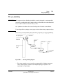
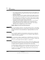
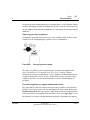
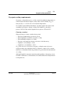
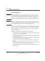
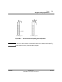
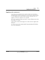
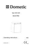
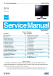
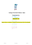
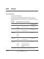
520
Gases
Gas requirements
Gases for packed columns
The carrier gas you use depends upon the type of detector and the
performance requirements. Table 520-1 lists gas recommendations for
packed column use. In general, makeup gases are not required with packed
columns.
Table 520-1
Gas Recommendations for Packed Columns
Detector
Carrier Gas
Comments
Detector anode purge
or reference gas
Electron Capture
Nitrogen
Maximum sensitivity
Nitrogen
Argon/
Methane
Maximum dynamic range
Argon/Methane
Nitrogen
Maximum sensitivity
Hydrogen and
air for detector
Helium
Acceptable alternative
Flame Ionization
Flame
Photometric
Hydrogen
Hydrogen and air for
detector
Helium
Nitrogen
Argon
NitrogenPhosphorus
Thermal
Conductivity
Helium
Optimum performance
Nitrogen
Acceptable alternative
Helium
General use
Hydrogen
Maximum sensitivity (Note A)
Nitrogen
Hydrogen detection (Note B)
Argon
Maximum hydrogen sensitivity
(Note B)
Hydrogen and
air for detector
Reference must be same as
carrier
Note A: Slightly greater sensitivity than helium. Incompatible with some compounds.
Note B: For analysis of hydrogen or helium. Greatly reduces sensitivity for other compounds.
Jun 2001
Site Preparation
Agilent 6890 Gas Chromatograph Service Manual
1 of 14
520
Gases
Gas requirements
Gases for capillary columns
When used with capillary columns, GC detectors require a separate makeup
gas for optimum sensitivity. For each detector and carrier gas, there is a
preferred choice for makeup gas. Table 520-2 lists gas recommendations for
capillary columns.
Table 520-2
Gas Recommendations for Capillary Columns
Preferred
makeup gas
Second choice
Detector anode
purge or reference
gas
Hydrogen
Argon/Methane
Nitrogen
Helium
Argon/Methane
Nitrogen
Anode purge must
be same as makeup
Nitrogen
Nitrogen
Argon/Methane
Argon/
Methane
Argon/Methane
Nitrogen
Hydrogen
Nitrogen
Helium
Helium
Nitrogen
Helium
Nitrogen
Nitrogen
Helium
Hydrogen
Nitrogen
Helium
Nitrogen
Nitrogen
Nitrogen
Argon
Nitrogen
Helium
Nitrogen
Helium**
Nitrogen
Nitrogen
Helium**
Hydrogen*
Must be same
as carrier and
reference gas
Must be same
as carrier and
reference gas
Detector
Carrier
gas
Electron Capture
Flame Ionization
Flame
Photometric
NitrogenPhosphorus
Thermal
Conductivity
Helium
Hydrogen and
air for detector
Hydrogen and air for
detector
Hydrogen and
air for detector
Reference must be
same as carrier and
makeup
Nitrogen
2 of 14
Site Preparation
Agilent 6890 Gas Chromatograph Service Manual
Jun 2001
Gases
Gas requirements
520
* When using hydrogen with a thermal conductivity detector, vent the detector exhaust to a fume hood
or a dedicated exhaust to avoid buildup of hydrogen gas.
**Helium is not recommended as a makeup gas at flow rate> 5 mL/min Flow rates above 5 mL/min
shorten detector life.
Jun 2001
Site Preparation
Agilent 6890 Gas Chromatograph Service Manual
3 of 14
520
Gases
Gas requirements
Gas purity
Some gas suppliers furnish “instrument” or “chromatographic” purity grades
of gas that are specifically intended for chromatographic use. We recommend
these grades for use with the GC.
Generally, all gas supplies used should be in the 99.995% to 99.9995% purity
range. Only very low levels (< 0.5 ppm) of oxygen and total hydrocarbons
should be present. Oil-pumped air supplies are not recommended because
they may contain large amounts of hydrocarbons.
The addition of high-quality moisture and hydrocarbon traps immediately
after the main tank pressure regulator is highly recommended. Refer to the
next section, The gas plumbing, for more information on using traps.
Table 520-3
Gas Purity Recommendations
Carrier gases and capillary makeup gases
Helium
99.9995%
Nitrogen
99.9995%
Hydrogen
99.9995%
Argon/Methane
99.9995%
Detector support gases
4 of 14
Hydrogen
99.9995%
Air (dry)
Zero-grade or better
Site Preparation
Agilent 6890 Gas Chromatograph Service Manual
Jun 2001
Gases
The gas plumbing
520
The gas plumbing
WARNING
All compressed gas cylinders should be securely fastened to an immovable
structure or permanent wall. Compressed gases should be stored and handled
in accordance with the relevant safety codes.
Gas cylinders should not be located in the path of heated oven exhaust.
To avoid possible eye injury, wear eye protection when using compressed gas.
Follow the general plumbing diagram when preparing gas supply plumbing.
Two-stage regulation
On/off valve
Main supply
on/off valve
Moisture
trap
Hydrocarbon
Oxygen
trap
trap
Main gas
supply
Figure 520-1
General plumbing diagram
• Two-stage regulators are strongly recommended to eliminate pressure
surges. High-quality, stainless-steel diaphragm-type regulators are
especially recommended.
Jun 2001
Site Preparation
Agilent 6890 Gas Chromatograph Service Manual
5 of 14
520
Gases
The gas plumbing
• On/off valves mounted on the outlet fitting of the two-stage regulator are
not essential but are very useful. Be sure the valves have stainless-steel,
packless diaphragms.
• FID, FPD, and NPD detectors require a dedicated air supply. Operation
may be affected by pressure pulses in air lines shared with other devices.
• Flow- and pressure-controlling devices require at least 10 psi (138 kPa)
pressure differential across them to operate properly. Source pressures
and capacities must be high enough to ensure this.
• Auxiliary pressure regulators should be located close to the GC inlet
fittings. This insures that the supply pressure is measured at the
instrument rather than at the source; pressure at the source may be
different if the gas supply lines are long or narrow.
Supply tubing for carrier and detector gases
Caution
Do not use methylene chloride or other halogenated solvent to clean tubing
that will be used with an electron capture detector. They will cause elevated
baselines and detector noise until they are completely flushed out of the
system.
Gases should be supplied to the instrument only through preconditioned
copper tubing (part no. 5180-4196). Do not use ordinary copper tubing—it
contains oils and contaminants.
Caution
Do not use plastic tubing to supply detector and inlet gases to the GC. It is
permeable to oxygen and other contaminants that can damage columns and
detectors, and can melt if near hot exhaust or components.
The tubing diameter depends upon the distance between the supply gas and
the GC and the total flow rate for the particular gas. One-eighth-inch tubing
is adequate when the supply line is less than 15 feet (4.6 m) long.
Use larger diameter tubing (1/4-inch) for distances greater then 15 feet (4.6
m) or when multiple instruments are connected to the same source. You
should also use larger diameter tubing if high demand is anticipated (for
example, air for an FID).
6 of 14
Site Preparation
Agilent 6890 Gas Chromatograph Service Manual
Jun 2001
Gases
The gas plumbing
520
Be generous when cutting tubing for local supply lines—a coil of flexible tubing
between the supply and the instrument lets you move the GC without moving
the gas supply. Take this extra length into account when choosing the tubing
diameter.
Two-stage pressure regulators
To eliminate pressure surges, use a two-stage regulator with each gas tank.
Stainless steel, diaphragm-type regulators are recommended.
Figure 520-2
Two-stage pressure regulator
The type of regulator you use depends upon gas type and supplier. The
Chemical Analysis Consumables and Accessories catalog contains
information to help you identify the correct regulator, as determined by the
Compressed Gas Association (CGA). Agilent Technologies offers pressureregulator kits that contain all the materials needed to install regulators
properly.
Pressure regulator-gas supply tubing connections
The pipe-thread connection between the pressure regulator outlet and the
fitting to which you connect the gas tubing must be sealed with Teflon tape.
Instrument grade Teflon tape (part no. 0460-1266), from which volatiles have
been removed, is recommended for all fittings. Do not use pipe dope to seal
the threads; it contains volatile materials that will contaminate the tubing.
Jun 2001
Site Preparation
Agilent 6890 Gas Chromatograph Service Manual
7 of 14
520
Gases
The gas plumbing
Traps
Using chromatographic-grade gases insures that the gas in your system is
pure. However, for optimum sensitivity, it is highly recommended that you
install high-quality traps to remove traces of water or other contaminants.
After installing a trap, check the gas supply lines for leaks.
Table 520-4
Recommended Traps
Description
Part No.
Preconditioned moisture trap: metal casing, s-shaped trap for carrier gas cleanup.
Contains Molecular Sieve 5A, 45/60 mesh, and 1/8-inch fittings.
5060-9084
Hydrocarbon trap: metal casing, s-shaped trap filled with 40/60 mesh activated
charcoal, and 1/8-inch fittings
5060-9096
Oxygen trap (for carrier and ECD gases): metal casing, and 1/8-inch brass fittings.
Oxygen trap cannot be reconditioned.
3150-0414
Moisture in carrier gas damages columns. We recommend a type 5A Molecular
Sieve trap after the source regulator and before any other traps.
A hydrocarbon trap removes organics from gases. It should be placed after a
molecular sieve trap and before an oxygen trap, if they are present.
An oxygen trap removes 99% of the oxygen from a gas plus traces of water. It
should be last in a series of traps. Because trace amounts of oxygen can
damage columns and degrade ECD performance, use an oxygen trap with
carrier and ECD gases. Do not use it with FID, FPD, or NPD fuel gases.
Oxygen trap
Molecular sieve or hydrocarbon trap—both are S-shaped
Figure 520-3
8 of 14
Traps
Site Preparation
Agilent 6890 Gas Chromatograph Service Manual
Jun 2001
Gases
Cryogenic cooling requirements
520
Cryogenic cooling requirements
Cryogenic cooling allows you to cool the oven below ambient temperature. A
solenoid valve introduces liquid coolant, either carbon dioxide (CO2) or
nitrogen (N2), to cool the oven to the desired temperature.
CO2 and N2 require different hardware. You must replace the entire valve
assembly if you want to change coolants. The liquid CO2 valve kit is
part no. G1565-65510 and the liquid N2 kit is part no. G1566-65517.
Choosing a coolant
When selecting a coolant, consider these points:
•
•
•
•
•
The lowest temperature you need to reach
How frequently you will use cryogenic cooling
The availability and price of coolant
The size of the tanks in relation to the size of the laboratory
Liquid N2 cools reliably to –80°C
• Liquid CO2 cools reliably to –40°C
CO2 is the choice for infrequent cryogenic cooling because it does not
evaporate and is less expensive than N2. However, a tank of CO2 contains
much less coolant than a tank of N2 and more CO2 is used for the same amount
of cooling.
Although liquid N2 evaporates from the tank regardless of frequency of use,
N2 tanks contain more coolant than do CO2 tanks and therefore may be better
for frequent use.
Jun 2001
Site Preparation
Agilent 6890 Gas Chromatograph Service Manual
9 of 14
520
Gases
Cryogenic cooling requirements
Using carbon dioxide
WARNING
Pressurized liquid CO2 is a hazardous material. If CO2 escapes its container,
it exits at high pressure and low temperatures that can be dangerous to
personnel. CO2 in high concentrations is toxic to humans. Consult your local
supplier for recommended safety precautions and delivery system design.
Caution
Liquid CO2 should not be used as a coolant for temperatures below –40°C
because the expanding liquid may form solid CO2—dry ice—in the GC oven. If
dry ice builds up in the oven, it can seriously damage the GC.
Liquid CO2 is available in high-pressure tanks containing 50 pounds of liquid.
The CO2 should be free of particulate material, oil, and other contaminants.
These contaminants could clog the expansion orifice or affect the proper
operation of the GC.
Additional requirements for the liquid CO2 system include:
• The tank must have an internal dip tube or eductor tube to deliver liquid
CO2 instead of gas (see Figure 520-4).
• The liquid CO2 must be provided to the GC at a pressure of 700 to 1,000 psi
at a temperature of 25°C.
• Use 1/8-inch diameter heavy-wall stainless steel tubing for supply tubing.
The tubing should be between 5 to 50 feet long.
• Coil and fasten the ends of the tubing to prevent it from “whipping” if it
breaks.
• Do not install a pressure regulator on the CO2 tank, as vaporization and
cooling would occur in the regulator instead of the oven.
• Do not use a padded tank (one to which another gas is added to increase
the pressure).
10 of 14
Site Preparation
Agilent 6890 Gas Chromatograph Service Manual
Jun 2001
Gases
Cryogenic cooling requirements
520
Dip tube
Correct configuration
Figure 520-4
WARNING
Incorrect configuration
Correct and incorrect liquid CO2 tank configuration
Do not use copper tubing or thin-wall stainless steel tubing with liquid CO2.
Both harden at stress points and may explode.
Jun 2001
Site Preparation
Agilent 6890 Gas Chromatograph Service Manual
11 of 14
520
Gases
Cryogenic cooling requirements
Using liquid nitrogen
WARNING
Liquid nitrogen is a hazard because of the extremely low temperatures and
high pressures that may occur in improperly designed supply systems.
Liquid nitrogen can present an asphyxiant hazard if vaporizing nitrogen
displaces oxygen in the air. Consult local suppliers for safety precautions and
design information.
Liquid nitrogen is supplied in insulated Dewar tanks. The correct type for
cooling purposes is a low-pressure Dewar equipped with a dip tube—to deliver
liquid rather than gas—and a safety relief valve to prevent pressure build-up.
The relief valve is set by the supplier at 20 to 25 psi.
WARNING
If liquid nitrogen is trapped between a closed tank valve and the cryo valve
on the GC, tremendous pressure will develop and may cause an explosion.
For this reason, keep the delivery valve on the tank open so that the entire
system is protected by the pressure relief valve.
To move or replace a tank, close the delivery valve and carefully disconnect
the line at either end to let residual nitrogen escape.
Additional requirements for the liquid N2 system include:
• Nitrogen must be provided to the GC as a liquid at 20 to 30 psi.
• The supply tubing for liquid N2 must be insulated. Foam tubing used for
refrigeration and air-conditioning lines is suitable for insulation. Since
pressures are low, insulated copper tubing is adequate.
• The liquid nitrogen tank should be close (only 5 to 10 feet) to the GC to
insure that liquid, not gas, is supplied to the inlet.
12 of 14
Site Preparation
Agilent 6890 Gas Chromatograph Service Manual
Jun 2001
Gases
Supplying valve actuator air
520
Supplying valve actuator air
Some valves use pressurized air for actuation (others are electrically or
manually driven). Actuator air must be free of oil, moisture, and particulates.
It can be supplied from a dried regulated cylinder, although “house” air
supplies or air from a compressor are acceptable.
Most valves require 20 to 40 psi of pressure to operate. High-pressure valves
may require 65 to 70 psi.
Valves require a dedicated air supply. Do not share valve air supplies with
detectors.
See "Valve Control" in the Agilent 6890 GC Operating Manual/CD-ROM for
more valve requirements.
Jun 2001
Site Preparation
Agilent 6890 Gas Chromatograph Service Manual
13 of 14
520
14 of 14
Gases
Supplying valve actuator air
Site Preparation
Agilent 6890 Gas Chromatograph Service Manual
Jun 2001