1
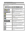
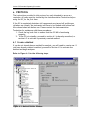
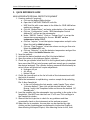
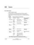
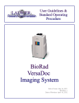
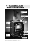
User Guidelines & Standard Operating Procedure for the Varian 3800 GC GC/MS Standard Operating Procedure ii TABLE OF CONTENTS DISCLAIMER ................................................................................iii ACKNOWLEDGEMENTS .................................................................... iv 1. INTRODUCTION........................................................................1 1.1 Purpose of the Standard Operating Procedure .............................1 1.2 Theory ............................................................................1 1.2.1 Simple Gas Chromatography .............................................1 1.2.2 Instrumentation............................................................2 1.2.3 Sample Preparation Suggestions.........................................7 1.3 Varian 3800 GC Software Overview ..........................................7 2. POTENTIAL HAZARDS............................................................... 10 3. PERSONAL PROTECTIVE EQUIPMENT ............................................. 10 4. SPILL AND ACCIDENT PROCEDURES .............................................. 11 4.1 Accidents ....................................................................... 11 4.2 Spills ............................................................................ 11 5. WASTE DISPOSAL PROCEDURES ................................................... 11 6. PROTOCOL........................................................................... 12 6.1 Create a Method .............................................................. 12 6.2 Sample Analysis ............................................................... 16 6.3 Standby ......................................................................... 17 6.4 Data Viewing and Analysis ................................................... 17 7. TROUBLESHOOTING ................................................................ 19 8. PREVENTATIVE MAINTENANCE .................................................... 19 8.1 Daily ............................................................................ 19 8.2 Weekly.......................................................................... 19 8.3 Monthly ......................................................................... 19 8.4 Six Months...................................................................... 20 8.5 Annually and As Required.................................................... 20 9. QUICK REFERENCE GUIDE.......................................................... 21 APPENDIX 1: GC-FID USER LOG......................................................... 24 APPENDIX 2: PREVENTATIVE MAINTENANCE LOG .................................... 26 GC/MS Standard Operating Procedure iii DISCLAIMER The materials contained in this document have been compiled from sources believed to be reliable and to represent the best opinions on the subject. This document is intended to serve only as a starting point for good practices and does not purport to specify minimal legal standards. No warranty, guarantee, or representation is made by Laurier as to the accuracy or sufficiency of information contained herein, and Laurier assumes no responsibility in connection therewith. iv Varian GC Standard Operating Procedure ACKNOWLEDGEMENTS The following individuals of Laurier contributed to the writing, editing, and production of this manual: Gena Braun (Instrumentation Technician). This manual was prepared for Laurier. Any corrections, additions or comments should be brought to the attention of the Instrumentation Technician at 519-884-0710 ext. 2361. Issued: August 2009 Revision: 0 Varian GC Standard Operating Procedure 1 1. INTRODUCTION 1.1 Purpose of the Standard Operating Procedure This standard operating procedure (SOP) is NOT a substitute for training and/or reading the appropriate manuals before use. All principle investigators and supervisors should document that training has been received by students and staff who will be using the Varian 3800 GC. A list of authorized users will be kept by the Instrumentation Technician. This SOP is intended to promote consistent and safe use of the Varian 3800 GC within the Faculty of Science. This SOP covers the potential hazards, personal protection requirements, spill and accident procedures, waste disposal considerations, and instrument operation for the Varian 3800 GC [henceforth referred to as the GC]. 1.2 Theory 1.2.1 Simple Gas Chromatography Chromatography is the science of separation; a sample that passes though a chromatographic bed or column will be distributed between a stationary phase and a mobile phase based on physical properties or chemical interactions. As a result of these interactions, the components in the sample travel through the column at different rates and can be separated (Meyer, 2004). The stationary phase can be composed of extremely small solid particles, or a thin liquid film coated on a solid support; the mobile phase can be a liquid or gas, but in the case of gas chromatography it is always a gas. Samples can introduced to the gas chromatograph (GC) as a liquid, which is then vapourized in the injector, or as a gas. The vapourized or gaseous sample is carried into the column with an inert carrier gas, such as helium. Separation is based primarily on boiling point and there temperature of the column oven must be carefully controlled. The chemistry of the adsorbed stationary phase also influences separation, but no to the same extent as in liquid chromatography. The separated sample components exit the column at different times and are detected by the appropriate detector. The final signal is sent to a computer where it can be compared to the signal from a known standard and quantified using chromatography software. 2 Varian GC Standard Operating Procedure In general, gas chromatography can be used to analyze any compounds that will volatilize at temperatures below approximately 350 oC and not be degraded or react with other compounds at these temperatures. If the volatility of a compound is not known, it may be estimated based on molecular weight, polarity, and structure. Hydrocarbons with molecular weights over 500 have be analyzed by GC, while small sugars and amino acids, with many polar amine and hydroxyl groups, are not suitable for GC analysis. Most organic compounds can be analyzed by GC as long as they are not thermally labile, while most inorganic compounds typically are not volatile enough. (Summarized from Rood, 2007). 1.2.2 Instrumentation The primary components of a GC include: the carrier and detector gases, flow controllers or valve, an injection port, the column and oven, a detector, and a recorder (Figure 1-1). Syringe Flow Control Injector Molecular Sieve Column Detector Oven Computer or Integrator Detector Gas Carrier Gas Figure 1-1: Basic Gas Chromatograph Varian GC Standard Operating Procedure 3 1.2.2.1 Carrier and Detector Gases The mobile phase is composed of an inert carrier gas that sweeps past the injector and transports the sample components through the column. The most common carrier gas is helium, although nitrogen, argon, and even hydrogen can be used. Carrier gas selection depends on the detector in use, column characteristics, the sample matrix, safety considerations, and cost. If capillary columns are used, the most popular carrier gases are helium and hydrogen, which provide high efficiency (high theoretical plate count) over a wide range of flow rates. Nitrogen, which can provide very high efficiency but only for very low flow rates, is commonly used with packed columns (Grob and Barry, 2004) 1.2.2.2 Injectors Injectors fit into two main classes: vapourization and on-column. Vapourization injectors can be split, splitless, or direct, and on-column can be direct or cooled. The overall purpose of the injector is to deposit the sample onto the column in the narrowest band possible with minimal discrimination between sample components. Vapourization Split/splitless injectors are heated and cause the sample to vapourize before it enters the column. Injector temperatures are usually set to ca. 50oC above the boiling point of the least volatile component of the mixture. The split/splitless design determines the amount of sample that enters the column. A splitless injector is typically used for trace level analysis and transfers the entire sample into the column. A split injector sweeps a predetermined potion of the sample out of the injector through the split vent and the remaining small portion of the sample enters the column. A split injection allows a reasonable amount of concentrated sample (0.1 to 10 g / l) to be injected without overloading the column. Injection speed should be as high as possible for a split injection, and can be slower for a splitless injection. Figure 1-2: Varian 1079 split/splitless injector (Varian GC/MS Manual) On-column injectors deposit the liquid sample directly onto the front of the column or a sort piece of deactivated silica called the “retention gap”. The sample then vapourizes as the temperature of the injector is increased. Cool on-column injections are ideal for heat sensitive samples and high boiling point compounds or other samples that experience significant discrimination in vapourization injectors. Direct injections are usually done for large ID columns (0.45 to 0.53 mm). Varian GC Standard Operating Procedure 4 Most injectors use a liner. The liner resides inside the injector and protects the injector body from the sample, mixes the sample, and affects the volume of sample that can be injected. When the sample is injected into a vapourization injector it vapourizes rapidly, and if the vapour volume is larger that the injector liner the sample may “flash-back” into the gas lines and injector body, and cause cross contamination between samples. Samples volumes are typically 1 l, but should be adjusted depending on the expected vapour volume of the mixture and the loading capacity of the column. Liners with frits or complex inner surfaces are usually used with split injections and create a turbulent flow path that mixes the sample as it is vapourized to minimize injector discrimination. Splitless injections are typically done with a straight liner with a restriction at one or both ends. Specially designed liners are required for oncolumn injections. Deactivated liners should be used in all cases. Septum purge is used to prevent septum bleed components from entering the column and is usually set at a fixed rate (1-3 ml/min) and does not need to be changed. Figure 1-3 illustrates the Varian 1079 injector currently used in the GC/MS system. 1.2.2.3 Capillary Columns GC columns come in a variety of styles, but the most popular are capillary columns which consist of a fused silica tube that has a thin coating of chemically bonded stationary phase on the inside and a polyimide coating on the outside to provide strength. Column stationary phase selection depends on sample components, desired column lifetime, and cost. The components of the sample are primarily separated based on volatility and therefore temperature. The stationary phase must be stable above the temperatures required for separation. Most columns can be operated at temperatures up to 350 for a brief period or 325 for an extended period. Lower temperatures can provide better separation but lead to a longer run time and peak broadening. Oven temperature is often increased as a run progresses to liberate the least volatile compounds. Column stationary phase does play a small roll in sample separation. The polarity of the column does not significantly influence separation, but does determine the capacity of the column: a more polar stationary phase will have a higher capacity for polar components. A less polar column, such as 100% methyl polysiloxane, is typically more stable and will have a longer lifetime. Column selectivity, based on intermolecular forces such as dispersion, dipole, and hydrogen bonding, does influence separation. Dispersion forces are the primary selection mechanism and are present with all stationary phases: smaller compounds and compounds with low solubility will experience lower retention due to dispersion Varian GC Standard Operating Procedure 5 Stationary phases are typically composed of polysiloxanes with methyl, phenyl, cyanopropyl, or trifluoropropyl substitutions. Substituted polysiloxanes are very robust columns and usually have a very long lifetime. Arylene-modified polysiloxanes are not as robust, but have a very low bleed and are ideal for mass spectrometry detection. Polyethylene glycol (PEG) columns can provide unique separation characteristics for difficult mixtures but are easily damaged. Porous layer open tubular (PLOT) columns are uniquely designed for the analysis of gases at room temperature. Stationary phases can also be bonded or non-bonded: bonded phases are more stable and generally preferred. Columns can be up to 100 meters in length with inner diameters between 0.1 to 5 mm. Longer columns with smaller diameters provide better resolution, but cost increases with length, and capacity generally decreases as diameter decreases. All stationary phases are broken down by oxygen at higher temperatures, although some are more sensitive than others, and great care must be taken to ensure minimal exposure by maintaining a sufficient flow of high purity dry helium and regular leak checking. 1.2.2.4 Detectors A GC can be equipped with several different detectors, and many models will be designed to accommodate two types of injectors, two columns, and two different detectors. Table 1-1 lists some of the common detectors used in gas chromatography. The Varian GC is equipped with an FID and a mass spectrometer. In the FID, organic compounds burn in a hydrogen and air flame and produce ions and electrons which conduct electricity through the flame. The resulting current is proportional to the amount of the compound. The mass spectrometer converts gaseous molecules to ions which are then separated by a quadrupole mass filter and detected. The mass spectrometer is discussed in greater detail in the Varian GC/MS Standard Operating Procedure. 6 Varian GC Standard Operating Procedure Table 1-1: Common detectors for a GC (Sheffield Hallam University) Detector Flame ionization (FID) Thermal conductivity (TCD) Electron capture (ECD) Nitrogenphosphorus Flame photometric (FPD) Photo-ionization (PID) Mass spectrometer (MS) Selectivity Most organic compounds Universal detector for nonorganic compounds Halides, nitrates, nitriles, peroxides, anhydrides, organometallics Nitrogen, phosphorus Sulphur, phosphorus, tin, boron, arsenic, germanium, selenium, chromium Aliphatics, aromatics, ketones, esters, aldehydes, amines, heterocyclics, organosulphurs, some organometallics Universal detector for ionizable compounds Limit of Detection Dynamic range 100 pg 107 1 ng 107 50 fg 105 10 pg 106 100 pg 103 2 pg 107 fg levels 107 Varian GC Standard Operating Procedure 7 1.2.3 Sample Preparation Suggestions 1.2.3.1 Calibration Standards The signal produced by the detector is unique for each compound and must be compared to a known sample for identification and quantification. Calibration standards must therefore be used, and are typically run as the first injections each day or with each set of samples. The lowest concentration standard should be run first, and should be at or slightly below the lowest expected sample concentration. The highest standard should be at or slightly above the highest expected sample concentration, and should be run as the last standard. The remaining standards should be evenly distributed between the highest and lowest standards, and there should be a minimum of 3 standards in total. 1.2.3.2 Internal Standards If samples are diluted or extracted before analysis, a set of control standards should be processed in the same way to determine the effects of sample preparation. Alternatively, each sample can be spiked with a known amount of a standard, and the final calculated concentrations following chromatography can be normalized based on the concentration of this “internal” standard. Use of an internal standard overcomes problems such as inconsistent injection volumes and is highly recommended for GC analyses. 1.3 Varian 3800 GC Software Overview The Saturn GC/MS is controlled using the Workstation v. 5.51 software. This software is used to develop and control methods, run single or multiple samples, and view and modify run results. The main applications are accessed via the Star toolbar; those related to GC operation are listed in Table 1-2. This toolbar also has buttons for the most recently used method and the most recently viewed data file. All sample analyses and methods are run through the System Control Application, and this window should be left open at all times when the GC is running or in standby. The System Control toolbar is located below the Star toolbar. Table 1-3 illustrates the System Control toolbar and describes the function of each button. 8 Varian GC Standard Operating Procedure Table 1-2: Star Toolbar Description Star Toolbar Application Button System Control Purpose System control is used to monitor instrument status and control sample analyses. This window is always left open if the GC is running or in standby. Method Editor The Method Editor is used to view and edit instrument operation, data acquisition, and data handling methods. Automation File Editor Automation File Editor allows editing of Sample Lists, Recalculates, and Sequences while the GC is running other methods. Interactive Graphics Interactive Graphics is used to view sample chromatograms, adjust integration parameters, and recalculates results. GC Report Viewer The Report Viewer can be used to view GC results and modify the report to include a variety of method and run information. GC Batch Reporting Batch reporting is used to create standard reports for a group of data files. Quick Start Quick Start is used to activate a method and run a single sample without generating a SampleList. Varian GC Standard Operating Procedure 9 Table 1-3: System Control Toolbar Description System Control Tool Button Purpose Toolbar illustration: Create a new automation file, select a previously created automation file, or edit notes for an automation file. Automation files are used to …. View, edit, or reactivate an instrument method. Activate an instrument method Edit module information for an on-line module. A “module” is an instrument component, such as the 3800 GC or the 8200 autosampler. Inject a single sample. Start a recalculation list, sample list, or sequence list respectively(the list must already be open). Pause automation. The sample that is currently running will be completed, and then the automation will be suspended. When the Begin button is pressed, the list will resume from the point when it was suspended. Begin running a list. Immediately stops automation and cancels the current run. If the Begin button is pressed, automation will start from the first row of the active list. Varian GC Standard Operating Procedure 10 2. POTENTIAL HAZARDS The GC is connected to several gas cylinders. These cylinders must remain upright and secured during use. When cylinders are empty (around 200 psi), they must be turned off and capped before transport. Cylinder replacement on the GC is done by the Instrumentation Technician only. The FID is connected to a hydrogen cylinder. Hydrogen is a highly flammable gas, and care must be taken to ensure that there are no leaks from this cylinder and that it is turned off after use. The helium gas that flows into the GC column is purified and dried by a converter tube that contains zirconium. This tube may explode if it is heated in the presence of air. NEVER disconnect the converter tube if the converter tube oven it turned on. The GC oven, injector, and detector operate at high temperatures. Do not open the oven door or try to access the detector or injector while the instrument is set at operating temperatures. 3. PERSONAL PROTECTIVE EQUIPMENT Standard laboratory protective equipment must be worn (latex or nitrile gloves, lab coat). Closed-toe and heel footwear constructed of resistant material is also required for all laboratory activities. See the WLU Laboratory Health and Safety Manual for additional information on personal protective equipment: http://www.wlu.ca/documents/23120/Laboratory_Health_%26_ Safety_Manual__Feb_2007_Final.pdf. Varian GC Standard Operating Procedure 11 4. SPILL AND ACCIDENT PROCEDURES 4.1 Accidents If you notice anything unusual concerning GC operation (smells, noises, etc.) contact the Instrumentation Technician immediately. All incidents must be reported to the Instrumentation Technician and if applicable, a student’s supervisor. The Instrumentation Technician will insure that all accidents, incidents and near misses involving instruments are reported as promptly as possible to the Environmental/Occupational Health and Safety (EOHS) Office via the WLU Employee Accident/Incident/Occupational Disease Report form (www.wlu.ca/eohs/forms). All incidents that result in critical injuries must be reported immediately to the EOHS Office by telephone. Additional details regarding incident reporting can be found in the WLU Accident Incident Procedure (www.wlu.ca/eohs). 4.2 Spills The WLU Laboratory Health and Safety Manual provides detailed instructions for dealing with major and minor spills. Do not attempt to clean up a spill if you have not been properly trained, or if you are unsure of the proper procedures. Before using ANY hazardous materials, make sure you understand the proper clean-up procedure. The Environmental/Occupational Health and Safety Office is also available to provide guidance at ext. 2874. See the WLU Laboratory Health and Safety Manual for further details. If a spill occurs ON or IN the GC, contact the Instrumentation Technician IMMEDIATELY. 5. WASTE DISPOSAL PROCEDURES All WHIMIS, Department, and Health and Safety guidelines must be followed for disposal of the substance to be analyzed. See the WLU Laboratory Health and Safety Manual for details. Varian GC Standard Operating Procedure 12 6. PROTOCOL The instructions provided in this protocol are only intended to serve as a reminder; all users must be trained by the Instrumentation Technician before using the GC for the first time. If the GC is completely shutdown (all components are turned off and the gas cylinders are closed), the instrument will have to be flushed with helium and the column baked-out before use. Please contact the Instrumentation Technician for assistance with these procedures. 1. Check the log book first to ensure that the GC/MS is functioning properly. 2. If the GC is in standby, proceed to section 6.1 to develop a method, or section 6.2 to activate a previously created method. 6.1 Create a Method If you do not already have a method for analysis, you will need to create one. If you have already created a method, proceed to Section 6.2 to activate the method and begin analyses. Refer to Figure 6-1 for the following steps. Figure 6-1: Method Builder Window Varian GC Standard Operating Procedure 13 1. Click on the Method Editor button on the Star toolbar (second button in then toolbar at the top of the screen; see Table 1-1 for a illustration of this button). 2. Select Open an Existing Method File. Look in the Templates folder and select the GC METHOD TEMPLATE.mth file. This file is configured for liquid sample analysis on the GC using the autosampler and FID detector. 3. SAVE this file with a new name in the folder for YOUR LAB before making any changes. 4. The top-most item in the tree is the name of the Method file. An asterisk (*) follows the name if the Method file has been modified since it was opened or last saved. 5. Click on “Method Notes” and enter information related to the types of samples to be analyzed, a literature reference for the method (if applicable), your name and supervisor, and the date the method was created. 6. Click on “Configuration” under “8200 Autosampler Control – Address 26” a. The Carrousel Type should be 48 vials. b. For faster sample analysis, select Prep Ahead, and in the EndTime box enter a time that is 2 or 3 minutes shorter than the total run time. If sample analysis speed is not a concern, leave the Prep Ahead box unchecked and do not enter a number in the EndTime box. c. Select the desired sampling mode: i. Standard mode: the sample is injected with a solvent flush (do not select if the solvent peak is large and close to the peaks of interest). ii. Volatile Sample: Use with samples that are in a high vapour pressure solvent. The sample is injected with a solvent flush, slow plunger speed, and no upper air gap to minimize flashing during sampling. iii. Neat Sample: This mode minimizes the amount of solvent that is injected with the sample and the syringe is washed several times with the sample before injection. iv. Viscous Sample: For samples that have a higher viscosity than water. This mode uses slow plunger speeds and longer pauses to improve reproducibility. v. User Defined: Allows each of the sampling options to be selected manually; the recommended settings for this option are: Solvent Flush: Yes Syringe Wash time: 20 Solvent Plug size: 0 Vial Needle Depth: 90 Uptake Speed: 5 Upper Air Gap: Yes Lower Air Gap: Yes Varian GC Standard Operating Procedure 14 Pause Time: 2 Hot Needle Time: 0 Injection Rate: 5 Needle Residence Time: 0 vi. SPME refers to Solid Phase Microextraction; please contact the Instrumentation Technician if you would like to use this technique. d. Under Liquid Sampling Options: i. Select Solvent A Wash, Solvent B Wash, A then B Wash, or No Wash (No Wash may result in significant sample carry over and cross contamination). Note: Make sure the solvents used for washing are miscible with each other and with the sample solvent. ii. The syringe should be set at 10 L (this is the syringe that is installed on the 8200). 7. Under “3800 GC Control” Click on “Column Oven” to set up the temperature programming for the run: a. Make sure the Column Oven Coolant is set to OFF. b. Set the stabilization time between 0.5 and 2 minutes (the oven will stabilize at the set temperature for this amount of time before each injection). c. Use the table to program the column temperature for the run. DO NOT set the temperature above 300oC. (Please contact the Instrumentation Technician if you think you need to use a higher temperature): i. Enter the initial column temperature and hold time in the first row ( a rate cannot be set for the initial temperature). ii. Enter the second temperature, ramp rate, and hold time in the second row. After the hold time on the first temperature has elapsed, the oven will ramp to the second temperature at the rate specified in the second row, and then remain at that temperature for the hold time listed in the second row. iii. Enter any additional temperatures in the following rows. iv. Note: It is recommended to ramp the temperature up at the end of each run to remove any less volatile components from the column before the next injection. 8. Do not change any of the parameters under “Autosampler” or “Sample Delivery.” 9. Click on “Injector” to set the injector temperature and split ratio. a. Select the tab for Middle Injector. b. The Injector Type should be set at 1079 and should not require changing. c. Make sure the Injector Oven is ON and the Injector Coolant is OFF. d. Set the desired injection temperature in first row of the table, and enter a hold time that is equal to the Column Oven End Time shown at the bottom of the window. Note: Avoid ramping the Varian GC Standard Operating Procedure 15 injector temperature if possible as repeat temperature changes cause stress on the components and can cause eventual leaks. e. Click on the Split Ratio… button and enter the desired split ratio for the injection in the first row (set it to off for a splitless injection). Do not change the values in the second and third row. Click OK. For example: If a 1 l sample is injected and the split ratio is set at 4, 0.25 l of the sample will enter the column. 10.Click on “Flow/Pressure” to set the column carrier gas flow rate: a. Select the Middle EFC tab. b. The type must be set to “Type 1” and should not require changing. c. Use the table to set the desired column pressures for the run OR select Constant Column Flow Mode and enter the desired flow rate for the column (the GC will then automatically determine the required pressure adjustments to maintain the flow rate as the temperature changes in the oven). The pressure is typically set around 10 psi. Note: In constant pressure mode the column flow rate will decrease as column temperature increases. 11.Click on “Detector” to set the detector temperature and gas flow rates: a. Select the Middle Detector tab. b. The Detector Type must be set to FID and should not require changing. c. Make sure the Detector Oven and Electronics are set to ON. d. Enter the desired Detector Temperature. e. Do not change any of the values in the Adjustments box at the bottom of the window. 12.Do not change any of the settings in the “Output” or “Data Acquisition” windows. 13.Under “Data Handling” a. Do not change the settings under Integration Parameters, Verification Set-up, or Time Events Table. b. The Peak Table can be used to automatically label the peaks of interest. If you know the retention times of your analytes, they can be entered manually, or they can be entered at a later time following the injection of test standards. c. The Calibration Set-up is used to run calibration standards and automatically quantify unknowns based on the standard curve. If you would like to set up a standard curve automatically, please contact the Instrumentation Technician for assistance. 14.Save the method. 15.Proceed to Section 6.2 to active the method and begin analyses. Varian GC Standard Operating Procedure 16 6.2 Sample Analysis 1. Activate the desired method by clicking on third folder icon from the left on the system control tool button or using File Activate Method. 2. Open the valves on the hydrogen and air cylinders. 3. Check the gas cylinder levels and fill in the log book (each cylinder must have more than 200 psi total pressure and have enough gas to complete the desired analyses). The cylinder delivery pressures should already be set as follows and should not require adjustment: a. Hydrogen: 40 psi b. Air: 60 psi c. Helium: 80 psi If the actual delivery pressures are not the same as those listed above, contact the Instrument Technician for assistance. DO NOT adjust them yourself. 4. Check the rinse solvent on the far left side of the instrument and refill the bottle if needed. Cover the bottle with a gloved hand and refill in the fumehood. 5. While the instrument is equilibrating, create a sample list by selecting File New SampleList. a. Name the SampleList and save it in you lab folder. b. Under Sample Name, give a descriptive name for the sample or standard. c. Under Sample Type, select “Analysis”. d. Under Inj. indicate the number of injections to be made from each sample. e. Under Injection Notes include any notes that would be useful for sample identification or data analysis. f. Indicate the injection volume for each sample (0.5 to 1 L is a good starting point). g. Leave the remaining columns at the default values. h. In the row following the last sample, under Sample Type, select “Activate Method”, then click on the Autolink button, select Browse, look in the Templates folder and choose the method “GC Standby.mth”. When the GC has run all of the samples in the SampleList it will automatically switch to the stand-by method. i. Click on the Data Files… button and select the desired folder to save the data in. Leave the remaining boxes as the default values (and each sample will be saved in a file according to the sample name). j. Click on the “RecalcList” button and select the option “Files will not be appended to any RecalcList”. 6. Load the samples into the autosampler tray according to the order in the SampleList. You MUST use vials that are 12 x 32 mm. Contact the Instrumentation Technician if you are unsure if your vials are the correct size. 7. Click on Begin in the SampleList window. Varian GC Standard Operating Procedure 17 8. Observe the first injection to check for any problems and then occasionally check on the instrument as the analyses proceed. a. The results can be viewed using the GC Report Viewer button on the Star toolbar. If the integration is unsatisfactory, it can be viewed and adjusted using the Interactive Graphics button. See Section 6.4 for further information on viewing data in Interactive Graphics. 9. When the run is complete, the raw data can be exported by right clicking on the chromatogram (as displayed in Interactive Graphics), then selecting AIA Import/Export, then selecting Varian to AIA, then selecting the desired file and folder to save it in. Then select AIA to Text, select the .cdf file that was just created and press Open, select the Raw Data checkbox only, click OK, and save the results in the desired folder with the desired name. 6.3 Standby If the GC/MS will be used within the next two weeks, put the GC in stand-by as follows, otherwise contact the Instrumentation Technician to shut the instrument down completely. 1. When the run is complete, if the GC is not in standby, activate the standby method by selecting File Activate Method and choosing GC Standby.mth from the Template folder. 2. Turn off the hydrogen and air cylinders using the cylinder valves (do not adjust the regulators). 3. Check the programmed and actual flow rate in the “Middle Detector EFC Status” box and confirm that the make up gas (CH 1) flow rate in the instrument is 3 and the hydrogen (Ch 2) and air (Ch 3) flow rates are zero. 4. Note any problems or concerns in the log book, and list the number and types of injections run. 6.4 Data Viewing and Analysis Interactive Graphics can be used to view previously run chromatograms and peak area data, adjust peak start and end times, add timed events, and reintegrate if required. 1. Open up Interactive graphics using the button on the Star toolbar (it looks like a blue chromatogram). 2. Select the file(s) that you would like to view and press “<< Add to List”. Then click on “Open Files”. If you place the mouse over each of the tool buttons in this window, but do not click on the button, you will be able to view a brief description of what each button does. 3. To zoom in on a given area of the chromatogram, click on the left mouse button and then drag over the area to zoom. Varian GC Standard Operating Procedure 18 4. To view the peak area data for a given chromatogram, left click on the desired trace and select “View GC Results Only” Or “View Standard GC Report”. 5. If more than one file is open, the data can be overlaid or viewed in separate chromatograms by using the “Tile Chromatograms” and “Overlay Chromatograms” buttons. If the data is overlaid, click on the coloured squares at the top of the window to select which trace is on top and to view the baseline, and peak start and end indicators. 6. If you are not satisfied with the automatically identified peak start and end points, left click on the triangle that indicates the start/end and drag it to the desired position. Then press the “Reintegrate Now” button and view the GC results to see the recalculated peak area. 7. Right click on the area below the chromatogram to add Time Events, such as Solvent Reject (this will allow the area under the solvent peak to be integrated, but it will not appear in the GC report). Varian GC Standard Operating Procedure 19 7. TROUBLESHOOTING Thermo Fisher provides very useful troubleshooting on their website www.separatedbyexperience.com. The Instrumentation Technician is also available to assist with unusual GC results or other analysis problems. 8. PREVENTATIVE MAINTENANCE Users are not to perform maintenance. These procedures are carried out by the Instrumentation Technician. 8.1 Daily - Check the log book for any problems or concerns. Check column nuts are tight Condition column daily or as required Check gas supplies 8.2 Weekly - Change injector insert if necessary 8.3 Monthly Perform a leak check as follows: 1. DO NOT use a soap-based leak detection fluid. Use an alcohol such as isopropanol or a 50:50 mixture of isopropanol and water and use a syringe to place a few drops on the desired fitting. Monitor the area for bubble formation. 2. Set the column oven and the injector zone temperatures to 50°C and allow them reach this temperature. 3. Remove injector septum nut and install a new septum. 4. Remove the column from the injector and seal the injector with a capillary nut (03- 949551-00) with a no hole ferrule (28-694590-01). 5. The septum purge outlets are located on the top frame surrounding the column oven, behind the column oven door. Seal the septum purge by removing the outlet fitting from the septum purge valve and replacing it with a blank off plug (16-000154-00). 6. The split vent outlets are located on the left side panel of the 3800 with manual pneumatics or inside the pneumatics compartment with EFC. Seal the split vent outlet by installing a Swagelok union on the outlet tube and sealing it with a blank off plug. 7. With all outlet ports plugged, pressurize the system to 20 - 30 psi. This can be accomplished by adjustment of the Electronic Flow Control and setting carrier gas pressure. Varian GC Standard Operating Procedure 20 8. Shut off the carrier supply at the source and monitor the displayed pressure at the GC for 15 minutes. The pressure should not drop more than 0.5 psi in 15 minutes. 8.4 Six Months - Condition the system 8.5 Annually and As Required - - Change septa (typically every 50 - 100 injections) Replace the gas cylinders: o With typical usage an A-size cylinder of carrier gas should last for three to six months. o Before changing the carrier gas cylinder, cool the system to room temperature and unplug the converter tube furnace. o Allow the system to cool for at least one hour with carrier gas flowing. o Turn off the carrier gas cylinder and disconnect the carrier gas line from the back of the GC. o Attach a new cylinder and purge the lines and converter tube for 30 minutes at 100 ml/min. o Turn on the converter tube furnace and purge for an additional 60 minutes. o Reconnect the carrier gas line to the back of the GC. o Check the cylinder and fittings for leaks. Replace gas purifiers as required. o The High Capacity Gas Purifier tube removes oxygen and water from at least 60 tanks of heavily contaminated gas, containing 100 ppm of oxygen and/or water (one cylinder of UH 5.0 helium contains less than 2 ppm water and less than 1 ppm O2). Varian GC Standard Operating Procedure 21 9. QUICK REFERENCE GUIDE WEAR APPROPRIATE PERSONAL PROTECTIVE EQUIPMENT 1. Create a method if required: a. Click on the Method Editor button b. Open the GC METHOD TEMPLATE.mth file. c. SAVE this file with a new name in the folder for YOUR LAB before making any changes. d. Click on “Method Notes” and enter a description of the method. e. Click on “Configuration” under “8200 Autosampler Control – Address 26” and set up the autosampler d. Under “3800 GC Control” Click on “Column Oven” to set up the temperature programming for the run. DO NOT set the temperature above 300oC. e. Click on “Injector” to set the injector temperature and split ratio. Select the tab for Middle Injector. f. Click on “Flow/Pressure” to set the column carrier gas flow rate. Select the Middle EFC tab. g. Click on “Detector” to set the detector temperature and gas flow rates. Select the Middle Detector tab. 2. Save the method. 3. Activate the desired method using File Activate Method. 4. Open the valves on the hydrogen and air cylinders. 5. Check the gas cylinder levels and fill in the log book (each cylinder must have more than 200 psi total pressure and have enough gas to complete the desired analyses). The cylinder delivery pressures should already be set as follows and should not require adjustment: h. Hydrogen: 40 psi i. Air: 60 psi j. Helium: 80 psi 6. Check the rinse solvent on the far left side of the instrument and refill the bottle if needed. 7. While the instrument is equilibrating, create a sample list by selecting File New SampleList. a. In the row following the last sample, under Sample Type, select “Activate Method”, then click on the Autolink button, select Browse, look in the Templates folder and choose the method “GC Standby.mth”. 8. Load the samples into the autosampler tray according to the order in the SampleList. You MUST use vials that are 12 x 32 mm. Click on Begin in the SampleList window. 9. Observe the first injection to check for any problems and then occasionally check on the instrument as the analyses proceed. 10.When the run is complete, the raw data can be exported by right clicking on the chromatogram (as displayed in Interactive Graphics), then selecting AIA Import/Export, then selecting Varian to AIA, then Varian GC Standard Operating Procedure 22 selecting the desired file and folder to save it in. Then select AIA to Text, select the .cdf file that was just created and press Open, select the Raw Data checkbox only, click OK, and save the results in the desired folder with the desired name. 11.If the GC/MS will be used within the next two weeks, put the GC in stand-by as follows, otherwise contact the Instrumentation Technician to shut the instrument down completely. a. When the run is complete, activate the standby method by selecting File Activate Method and choosing GC Standby.mth from the Template folder. b. Turn off the hydrogen and air cylinders using the cylinder valves (do not adjust the regulators). 12.Note any problems or concerns in the log book, and list the number and types of injections run. 13.Interactive Graphics can be used to view previously run chromatograms and peak area data, adjust peak start and end times, add timed events, and reintegrate if required. Varian GC Standard Operating Procedure 23 REFERENCES Grob, RL. Barry, EF. 2004. Modern Practice of Gas Chromatography: Fourth Edition. Wiley and Sons, Inc: New Jersey. Rood, D. 2007. The Troubleshooting and Maintenance Guide for Gas Chromatographers: Fourth, Revised and Updated Edition. Wiley-VCH: Weinheim. Sheffield Hallam University. Gas Chromatography. http://teaching.shu.ac.uk/hwb/chemistry/tutorials/chrom/gaschrm.htm Accessed Aug 24, 2009. Varian Associates, Inc. 1998. Saturn GC/MS Workstation Version 5.2. Hardware Maintenance. Operator’s Manual. Wilfrid Laurier University Environmental/Occupational Health and Safety Office. 2007. Laboratory Health and Safety Manual. Varian GC Standard Operating Procedure APPENDIX 1: GC-FID USER LOG 24 25 Varian GC Standard Operating Procedure CYLINDER DATE NAME EXT # SUPERVISOR PRESSURES AT START H2:_________ AIR:_________ HE:_________ H2:_________ AIR:_________ HE:_________ H2:_________ AIR:_________ HE:_________ H2:_________ AIR:_________ HE:_________ H2:_________ AIR:_________ HE:_________ H2:_________ AIR:_________ HE:_________ H2:_________ AIR:_________ HE:_________ H2:_________ AIR:_________ HE:_________ H2:_________ AIR:_________ HE:_________ NUMBER OF INJECTIONS LIQUID:_______ VAPOUR: _____ TOTAL: ______ LIQUID:_______ VAPOUR: _____ TOTAL: ______ LIQUID:_______ VAPOUR: _____ TOTAL: ______ LIQUID:_______ VAPOUR: _____ TOTAL: ______ LIQUID:_______ VAPOUR: _____ TOTAL: ______ LIQUID:_______ VAPOUR: _____ TOTAL: ______ LIQUID:_______ VAPOUR: _____ TOTAL: ______ LIQUID:_______ VAPOUR: _____ TOTAL: ______ LIQUID:_______ VAPOUR: _____ TOTAL: ______ MIDDLE COLUMN HEAD PRESSURE (IN STANDBY) METHOD TEMPERATURES INJECTOR:_________ OVEN:____________ DETECTOR:________ INJECTOR:_________ OVEN:____________ DETECTOR:________ INJECTOR:_________ OVEN:____________ DETECTOR:________ INJECTOR:_________ OVEN:____________ DETECTOR:________ INJECTOR:_________ OVEN:____________ DETECTOR:________ INJECTOR:_________ OVEN:____________ DETECTOR:________ INJECTOR:_________ OVEN:____________ DETECTOR:________ INJECTOR:_________ OVEN:____________ DETECTOR:________ INJECTOR:_________ OVEN:____________ DETECTOR:________ PROBLEMS Varian GC Standard Operating Procedure APPENDIX 2: PREVENTATIVE MAINTENANCE LOG 26 27 Varian GC Standard Operating Procedure DATE NAME EXT # TYPE OF MAINTENANCE FREQUENCY OF MAINTENANCE (I.E. WEEKLY) PROBLEMS / COMMENTS