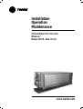
1
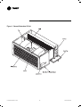
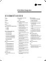
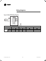
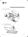
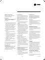
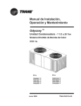
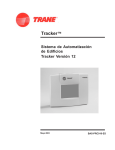
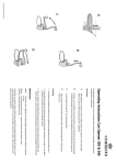
Installation
Operation
Maintenance
Chilled Water Fan Coil Unit
Maxxum™
Model:HCCA Size:10~24
HCCA-SVX01A-EN
Table Of Contents
General Information
3
Basic Unit / Fan Board / Coil / Drain Pan / Optional Plenum/Filters
Figure 1 : General Illustration Of Unit
HCCA Model Designation
5
Installation
6
Receiving And Handling
Installation Considerations
Mounting
Duct Connections
Piping
Electrical Connections
Table 1 : HCCA Unit Operating Weights
Table 2 : HCCA Unit Net Weights
Figure 2 : Typical Installation With Rear Return Plenum
Figure 3 : Duct Work
Coil Connections
9
Figure 4 : Model HCCA Coil Connections
10
Dimension Data
Figure 5 : HCCA Unit Without Plenum
Figure 6 : HCCA Unit With Rear Return Plenum
Figure 7 : HCCA Unit With Bottom Return Plenum
Figure 8 : S & T Drain Pan, For (Fig 5, 6, 7)
Wiring Diagrams
12
Figure 9 : Model HCCA Wiring Diagrams
Installation Checklist
13
Start Up/Operation
14
Maintenance
15
Periodic Maintenance Checklist
Maintenance Procedures
Figure 10 : HCCA Filter Assembly
Figure 11 : HCCA Plenum Assembly
Figure 12 : Fan Board Assembly
Figure 13 : HCCA Drain Pan Assembly
Maintenance Contract
Training
© American Standard Inc. 2003
2
HCCA-SVX01A-EN
General Information
This service manual covers the installation,
operation and maintenance of the Trane
HCCA chilled water Fan Coil. It should be
read thoroughly before installing the fan coil
Fan Board
All motors, with internal thermal temperature
cutout above 140°C, are permanent split-
unit.
capacitor, three speed, tap wound, induction
type for maximum efficiency. Motors have
Basic Unit
permanently lubricated ball bearings and alldirection, vibration isolating mountings to
The Trane Model HCCA fan coil unit
consisting rigid galvanized steel casing,
ensure vibration free operation and
minimum noise. Motor wiring is enclosed by
copper tube/aluminum fin coil type heat
exchanger, fan board assembly, manual coil
flexible metal conduit and connected to the
junction box. All motors are performed in-
air vent with drain pan, junction box with
terminal strip.
house test and finished unit test again prior
to shipment.
Unit casing manufactured by 1.2mm thick
galvanized steel with internal insulation of
All unit sizes have both ends shaft for motor.
The material of fan wheel is galvanized steel
9mm thickness, 108 kg/m3 high density nonflammable PU foam.
and mounted directly onto each shaft. The
DIDW centrifugal fans have balanced and
The standard unit is without return air
plenum, or selected with bottom return air
plenum or rear return air plenum in option,
while filter is another option associated to
the return air plenum.
forward curved blades. Fan housings are
made of galvanized sheet steel. The fan
board can be simply removed by loosening
the fasteners for easy service purpose.
Coil
Coils are 3/8 inch OD copper tubes
mechanically bonded to Wavy 3B aluminum
fin collars. A manual air vent with drain line
water drips when venting. Standard coils are
factory leak tested at 20 kg/cm2 (20 Bar)
and are recommended for operation up to
13kg/cm2 (13 Bar) working pressure.
Coils are fitted with either sweat connection
or female pipe thread connection. Cooling
while coil has one set of connection, hot
water heating option have two sets of
connection.
Available coils are 3 row cooling, 4 row
cooling, 6 row cooling, 3 row cooling + 1 row
heating, and 4 row cooling + 2 row heating.
Drain Pan
The drain pan is 25mm depth with 0.8mm
thickness galvanized steel c/w internal
epoxy resin coating.
For sure without leakage occur, the
fabrication of drain pan by one-piece
stamping process with seamless and no
joint. The standard insulation material is
5mm thickness, 27 kg/m3 density PE foam.
The drain pan has one 3/4-inch male pipe
thread (JIS B 0203-1966) connection.
to the drain pan is standard to avoid any
3
HCCA-SVX01A-EN
Figure 1 : General Illustration Of Unit
© American Standard Inc. 2003
4
HCCA-SVX01A-EN
HCCA Model Designation
H
1
C
2
C
3
A 14 C
4 5,6 7
N M 1 N A N C
8 9 10 11 12 13 14
DIGIT 1
H = High
DIGIT 2
C = Capacity
DIGIT 3
C = Concealed
DIGIT 4
A = Development Sequence
DIGIT 5,6 - Size / Nominal CFM (@100 Pa ESP)
10 = 1000 CFM
14 = 1400 CFM
18 = 1800 CFM
24 = 2400 CFM
DIGIT 7 - Coil Row, Connection Side
C = 3 Row Cooling, Right Hand
D = 3 Row Cooling, Left Hand
E = 4 Row Cooling, Right Hand
F = 4 Row Cooling, Left Hand
J = 3 Row Cooling, 1 Row Heating, Right Hand
K = 3 Row Cooling, 1 Row Heating, Left Hand
L = 4 Row Cooling, 2 Row Heating, Right Hand
M = 4 Row Cooling, 2 Row Heating, Left Hand
N = 6 Row Cooling, Right Hand
P = 6 Row Cooling, Left Hand
S = Special
DIGIT 8 - Electric Heat 220V (240V)
N = None
C = 2.0 kW(2.4 kW) Heater (Size 10~24)
D = 2.5 kW(3.0 kW) Heater (Size 10~24)
E = 3.0 kW(3.6 kW) Heater (Size 10~24)
F = 3.5 kW(4.2 kW) Heater (Size 10~24)
G = 4.0 kW(4.8 kW) Heater (Size 14~24)
H = 5.0 kW(6.0 kW) Heater (Size 18~24)
I = 6.0 kW(7.2 kW) Heater (Size 18~24)
J = 7.0 kW(8.4 kW) Heater (Size 24 Only)
K = 8.0 kW(9.6 kW) Heater (Size 24 Only)
S = Special
DIGIT 9 - Motor Type
M = Normal Capacity with Temperature Cutout
S = Special
DIGIT 10 - Voltage / Hertz / Phase
1 = 220-240 / 50 / 1
2 = 220-240 / 60 / 1
S = Special
DIGIT 11 - Water Connection
N = 2 Pipe System / Thread Connection / Without
Valve Package
B = 2 Pipe System / With Single 2-Way 2 Position
Valve/Without Thermostat
C = 2 Pipe System / With Single 2-Way 2 Position
Valve / With Cool Thermostat
D = 2 Pipe System / With Single 2-Way 2 Position
Valve / With Cool/Heat Thermostat
H = 4 Pipe System / With 2 Sets 2-Way 2 Position
Valve / Without Thermostat
I = 4 Pipe System / With 2 Sets 2-Way 2 Position
Valve / With Cool/Heat Thermostat
Y = 2 Pipe System / Sweat Connection / Without Valve
Package
1 = 2 Pipe System / With Single 2-Way 2 Position
Valve / With Trane Wall Mounted Zone Sensor /
ZN510 (Cooling Only)
2 = 2 Pipe System / With Single 2-Way 2 Position
Valve / With Trane Wall Mounted Zone Sensor /
ZN510 (Cooling & Heating)
3 = 2 Pipe System / With Single 2-Way Floating Valve
/ With Trane Wall Mounted Zone Sensor / ZN520
(Cooling Only)
4 = 2 Pipe System / With Single 2-Way Floating Valve
/ With Trane Wall Mounted Zone Sensor / ZN520
(Cooling & Heating)
5 = 2 Pipe System / With Single 3-Way 2 Position
Valve / With Trane Wall Mounted Zone Sensor /
ZN510 (Cooling Only)
6 = 2 Pipe System / With Single 3-Way 2 Position
Valve / With Trane Wall Mounted Zone Sensor /
ZN510 (Cooling & Heating)
7 = 2 Pipe System / With Single 3-Way Floating Valve
/ With Trane Wall Mounted Zone Sensor / ZN520
(Cooling Only)
8 = 2 Pipe System / With Single 3-Way Floating Valve
/ With Trane Wall Mounted Zone Sensor / ZN520
(Cooling & Heating)
5
DIGIT 12 - Drain Pan
A = STD. Galvanized Steel / 5mm PE Insulation
B = Long Galvanized Steel / 5mm PE Insulation
C = STD. SUS / 5mm PE Insulation
D = Long SUS / 5mm PE Insulation
E = STD. Galvanized Steel / 6mm Non-Flammable
BS476, Part7 Insulation
F = Long Galvanized Steel / 6mm Non-Flammable
BS476, Part7 Insulation
G = STD. SUS / 6mm Non-Flammable BS476, Part7
Insulation
H = Long SUS / 6mm Non-Flammable BS476, Part7
Insulation
I = STD. Galvanized Steel / 10mm PE Insulation
J = Long Galvanized Steel / 10mm PE Insulation
M = STD. Galvanized Steel / 15mm PE Insulation
O = Long Galvanized Steel / 15mm PE Insulation
S = Special
DIGIT 13 - Plenum / Filters
N = Without Return Plenum / No Filter
F = With Rear Return Plenum / No Filter
G = With Rear Return Plenum / 25mm Aluminum Filter
P = With Rear Return Plenum / 25mm Foam Filter
Q = With Bottom Return Plenum / No Filter
R = With Bottom Return Plenum / 25mm Aluminum Filter
T = With Bottom Return Plenum / 25mm Foam Filter
S = Special
DIGIT 14 - Design Sequence
C = Third
Notes:
1. The wiring of thermostat or zone sensor to motors,
ZN or valves must be done on job site.
2. Non-flammable PU insulation meet the regulation of
BS476 part7 class 1 and part6 class O.
HCCA-SVX01A-EN
Installation
CAUTION: The installation must be
conducted by a qualified technician.
Installation Considerations
Mounting
For proper installation and operation, check
each of the followings before mounting the
The Trane model HCCA units are designed
to be suspended from the ceiling on 3/8-16
Receiving And Handling
units:
Trane HCCA Fan Coil units are packaged in
individual cartons for maximum protection
during shipment, as well as for easy
handling and storage on the job site.
threaded rods furnished by the installer.
Holes are provided at the top of the unit, see
1. Allow adequate space for the unit and free
area or service clearances. See Figures
Figures 5, 6, 7 and 8 for cutout dimensions
and locations.
To protect against loss from in-transit
damage, complete the following upon receipt
of the units:
1. Inspect individual pieces of the shipment
before accepting it. Check for rattles, bent
corners on cartons or other visible
indications of shipping damage.
2. If a carton has apparent damage, open it
immediately and inspect the contents
before accepting the unit. Do not refuse
the shipment. Make specific notations
concerning the damage on the freight bill.
Check the unit casing, fan rotation, coils,
drain pan, filters and all options.
3. Inspect the unit for concealed damage
before it is stored and as soon as possible
after delivery.
4. Do not remove damaged material from
the receiving location if possible. It is the
receiver's responsibility to provide
reasonable evidence that concealed
damage was not incurred after delivery.
5. If concealed damage is discovered, stop
unpacking the shipment. Retain all
internal packing materials and original
cartons. Take photos of the damaged
material if possible.
6. Notify the carrier's terminal of damage
immediately by phone and mail if any
damage is found. Request an immediate
joint inspection of the damage by the
carrier and consignee.
7. Notify the Trane sales representative of
the damage and arrange for repair. Do not
repair the unit, however, until damage is
inspected by the carrier's representative.
© American Standard Inc. 2003
5, 6, 7 and 8 for general unit dimensions.
For other dimensions refer to the
submittal drawings provided by Trane
Sales Office not in carton. For servicing
and routine maintenance, must provide
access to the unit through removable
panels in the ceiling.
2. Before installing any unit make sure
proper preparation has been made at
each unit location for piping and electrical
connections.
3. Check that the supporting structure is
strong enough to support the operating
weights, as given on Table 1.
To install the Trane model HCCA, complete
the following:
1. Install the suspension rods or other
suspension devices which must be
provided by the installer.
2. Put the upper W3/8 nuts and W3/8 lock
washers on suspension rods to prevent
unit from upward tilting during unit
operation or duct installation, as shown on
Figure 2 Typical Installion.
3. Hoist the unit into position. See Table 2 for
unit net weights.
4. The clearance between drain pan and
ceiling should be enough for drain line
CAUTION: Due to the heavy weights.
ensure safety of all nearby installers
when hoisting the unit.
pitch with a minimun slope of 1:50.
5. Ducting connected to units (where
4. Put on the lower W3/8 lock washers and
applicable) should not exceed the external
static pressure rating of the unit.
6. Condensate protection for the chilled
water valves and piping must be provided
by installer. A drain pan extension
provided by installer should be located
under the valves or else the valves and
piping should be thoroughly insulated.
7. Units with valve package are equipped
with long drain pan which can carry the
condensation from water valves.
Insulation of valve package is not
then W3/8 nuts to secure the unit, as
shown on Figure 2 Typical Installion.
5. Place the unit to desired angle by
adjusting lower nuts up/down, and then
tignten the upper nuts.
6. Adjust the slope of the drain pan by
turning the drain pan suspension screws
up/down. The drain pan should be pitched
to provide proper drainage. Note side to
side as ewll as end to end level. See rain
”Pan Leveling” in maintenance procedures
for more details.
required.
Note: Level the unit by checking on the
unit casing. Do not use the coil or drain
pan for leveling as they are pitched to
provide proper drainage.
6
HCCA-SVX01A-EN
Duct Connections
Piping
Electrical Connections
Minimum 24 gauge galvanized sheet metal
duct (supplied by the installer) is recommended
Coil connections
To complete piping connections, attach the
For wiring and installion, refer to the wiring
diagram decals on each unit located on coil
to be attached to duct collars provided at the
unit air outlet and inlet (provided with plenum
water piping with famale connections copper
tube to the coil header and then sweat the
end panel. Also see Figure 9 for wiring
diagrams.
option only), see Figures 5, 6,7 and 8 for duct
collar dimensions.
connection area thoroughly. For optional
threaded connections, attach the water
To attach, slip the duct over the outlet collar
and fasten the duct and collar together with
screws or rivets, as shown on Figure 3 Duct
Work. Field-supplied transition fittings should
be used in installations where unit duct
collars do not match discharge air-grille
collars.
A return duct with plenum can be attached
to the return air collar provided at the return
plenum. To attach, slip the return duct over
the return air collar and fasten the duct and
collar together with screws.
piping with MPT connection to the coil
header and then fasten the connection. The
water inlet is on the bottom and water outlet
on the top of the coil. Coil connection size
and coil connection locations are given on
Figure 4. Refer to submittals for specific
connection locations.
Condensate Drain Connections
Either PVC pipe or steel pipe with 3/4-inch
FPT connection can be used as a drain line.
Attach the drain line to the drain connection
with tape-sealant to prevent leakage. A drain
line pitch with a minimum slope of 1:50 is
recommended.
A grounding point, which must be properly
connected to the building grounding system,
has been provided with a mark within the
Junction Box.
All electrical connections must comply with
local electrical codes and ordinances.
WARNING: Disconnect electrical power
source and secure in disconnected
position before servicing the unit. Failure
to do so may result in personal injury or
death from electrical shock.
CAUTION: Use only copper conductors
for wiring connections. Unit terminals are
not designed to accept other types of
wiring. Aluminum or other conductors
may cause overheating and unit damage.
Notice: The reserved space for power
supply cords is 20 mm in diameter.
Notice: Table shows the range of the fan
coil units with different heater options.
Please refer to the current and use the
proper power supply cords.
7
HCCA-SVX01A-EN
Table 1 : HCCA Unit Operating
Weights
Figure 2 : Typical Installation With Rear Return Plenum
HCCA Unit without Plenum Operating Weights (kg)
Row/Size
3ROW
4ROW
6ROW
10
50
54
62
14
54
59
70
18
71
76
88
24
81
90
105
HCCA Unit with Plenum Operating Weights (kg)
Row/Size
3ROW
4ROW
6ROW
10
64
68
76
14
69
74
85
18
90
95
107
24
106
115
132
Table 2 : HCCA Unit Net Weights
HCCA Unit without Plenum Net Weights (kg)
Row/Size
3ROW
4ROW
6ROW
10
47
50
56
14
50
54
62
18
66
70
79
24
75
82
93
HCCA Unit with Plenum Net Weights (kg)
Row/Size
3ROW
4ROW
6ROW
10
61
64
70
14
65
69
77
18
85
89
98
24
100
107
120
Figure 3 : Duct Work
© American Standard Inc. 2003
8
HCCA-SVX01A-EN
Coil Connections
Figure 4 : Model HCCA Coil Connections
Note:Dimension in mm
25.4mm = 1 inch
Cooling & Heating Coil Connection Dimension
Unit
10
Cooling
Heating
Coil Type
CONN.
SIZE
DIMENSION
A
B
C
D
E
F
G
H
Sweat (inch)
Thread (FPT)
Cooling
Heating
Cooling
Heating
14
18
24
3 Row
1 Row
109
153
182
187
100
228
60
263
7/8
5/8
4 Row
2 Row
65
131
165
208
88
228
154
216
7/8
5/8
3 Row
1 Row
109
153
182
182
152
229
66
290
7/8
5/8
4 Row
2 Row
65
131
165
200
139
229
165
170
7/8
7/8
3 Row
1 Row
109
153
182
182
152
229
66
290
7/8
5/8
4 Row
2 Row
65
131
165
200
139
229
165
170
7/8
7/8
3 Row
1 Row
109
153
182
208
152
229
174
181
7/8
5/8
3/4
3/4
3/4
3/4
3/4
3/4
3/4
Note:Dimension in mm
4 Row
2 Row
65
131
165
186
172
196
117
170
1-1/8
7/8
1
3/4
25.4mm = 1 inch
Cooling Coil Connection Dimension
CONN.
DIMENSION
SIZE
Unit
Coil Type
A
B
C
Sweat (inch)
Thread (FPT)
10
3R
131
88
215
7/8
3/4
4R
109
88
228
7/8
3/4
14
6R
65
88
228
7/8
3/4
3R
131
137
216
7/8
3/4
4R
109
137
229
7/8
3/4
9
18
6R
65
172
196
1-1/8
1
3R
131
137
216
7/8
3/4
4R
109
137
229
7/8
3/4
24
6R
65
172
196
1-1/8
1
3R
131
137
216
7/8
3/4
4R
109
172
196
1-1/8
1
6R
65
172
196
1-1/8
1
HCCA-SVX01A-EN
Dimension Data
Figure 5 : HCCA Unit Without Plenum
Figure 6 : HCCA Unit With Rear Return Plenum
© American Standard Inc. 2003
10
HCCA-SVX01A-EN
Figure 7 : HCCA Unit With Bottom Return Plenum
Figure 8 : S & T Drain Pan, For (Fig 5, 6, 7)
UNIT SIZE
HCCA-10
HCCA-14
HCCA-18
HCCA-24
Case & Drain Pan Size
A
887
963
1090
1623
B
921
997
1124
1657
C
189
157
171
163
D
*1164
*1208
*1349
*1874
External Dimension
D1
*1349
*1454
*1624
*2074
E
483
483
449
449
F
*748
*748
*799
*799
G
703
703
754
754
NOTES:
1. Dimension is mm.
2. Right hand coil connection shown.
3. External wiring, controls not supplied by Trane.
4. See coil connections size and location.
5. D=standard drain pan, D1=extend drain pan.
H
266
316
316
316
I
363
*416
416
416
J
*409
409
*448
*448
Without Plenum
L
310
310
361
361
M
825
901
1028
1561
N
370
370
412
412
O
889
965
1092
1625
Q
*706
*706
*758
*758
R
687
687
739
739
*Represent outine dimension of unit
11
HCCA-SVX01A-EN
Wiring Diagrams
Figure 9 : Model HFCA Wiring Diagrams
Factory Std. Wiring of HCCA-Standard Motor
Unit Size
Power Supply (Volt/Hz)
Wire Color
High
Medium
Low
© American Standard Inc. 2003
10
220/50
Yellow
Blue
Orange
14
220/60
Black
Yellow
Blue
220/50
Yellow
Blue
Orange
18
220/60
Black
Yellow
Blue
12
220/50
24
220/60
Black
Yellow
Blue
220/50
220/60
Black
Yellow
Blue
HCCA-SVX01A-EN
Installation Checklist
The following checklist is provided as an
abbreviated guide to the detailed installation
procedures given in this manual. This list
should be used by the installer to ensure
that all necessary procedures have been
completed. For more complete information,
refer to the appropriate sections in this
manual.
WARNING: Disconnect electrical power
source and secure in disconnected
position before servicing the unit. Failure
to do so may result in personal injury or
death from electrical shock.
CAUTION: Use only copper conductors
for wiring connections. Unit terminals are
not designed to accept other types of
wiring. Aluminum or other conductors
may cause overheating and unit damage.
• Units are checked for shipping damage.
• Unit location is prepared for weight,
leveling and service access.
• Unit is mounted securely to the ceiling
support rods.
• Ductwork connections are complete.
• Coil connections are complete and tight.
• Condensate drain pan connections are
complete and tight.
• Electrical connections are completed (fan
switches, thermostats).
• Ground connections are completed.
• Unit casing is reasonably level.
• Drain pan is adjusted and pitched to
provide proper drainage.
• Motor-blower assembly rotates freely.
• Units hydrostatically tested and air vented.
• Debris on the fan wheel and drian pan are
cleared.
• Start-up preparation is complete and unit is
in the proper pre-operating mode with
switch off.
• Owner-operator is instructed on unit
operation.
• IOM is properly stored for future reference.
13
HCCA-SVX01A-EN
Start Up / Operation
Start Up
Fan speed control can also be equipped (not
Before starting the unit, complete the above
mentioned INSTALLATION CHECKLIST to
provided by this unit) with automatic speed
control in which the control will adjust the fan
ensure the proper start-up preparation is
completed.
speed according to the desired set
temperature.
Operation
Two basic methods of fan coil control are
Although the units may operate with variable
speed control, Trane cannot warranty proper
available: (1) fan speed control and (2)
cycling of the waterflow to the unit coil. The
operation with any particular control. Contact
Trane if you have questions.
operation of the fan speed control can be
implemented by using a simple motor speed
switch, and a thermostat unit can be used to
control the cycling of waterflow.
All HCCA fan-coil motors have internal
thermal cutout. The motors will be deenergized if the internal temperature of a
motor exceeds 140˚C to protect the motors
The wall-mounted thermostat unit usually
includes a motor speed switch, an on/off
against over-heating and burning out. The
auto-reset function will resume the motor
switch and a thermostat. The on/off switch
turns the unit on and off, and the motor
operation when the internal temperature of
the motor drops below 140˚C.
speed switch controls the fan speed. The
thermostat controls the water line stop valve
and usually has a dial to select an
approxmate temperature.
Coil Venting
When water is first introduced into a coil, air
is sometimes trapped in the coil tubing. This
trapped air has a tendency to collect at the
Fan speed control is manually selected at
the appropriate position with the speed
highest point in the coil. Therefore, a manual
air vent is installed at the highest point of the
selector switch labeled Off-Hi-Med-Low. The
fan will run contnuously at the selected
header. When there appears to be air
trapped in the coil, resulting in "bubbling" or
speed until the occupant manually changes
the speed setting. lt is also possible to cycle
"lanking" noises within the unit, release air
from the manual air vent by rotating the
the fan, at the speed selected, using a
thermostat.
knob. A pair of pliers can be used if the knob
is too tight to turn by hand. Turn knob
counter clockwise 1-2 turns and allow air to
flow out of the air vent until a steady stream
of water appears. Then retighten knob.
© American Standard Inc. 2003
14
HCCA-SVX01A-EN
Maintenance
Periodic Maintenance Checklist
Maintenance Procedures
The following checklist is provided as a
recommended maintenance schedule.
Change/Clean Filters
Change or clean air filters at least twice a
Detailed instructions for specific
maintenance procedures are given after the
year. Filters will require more frequent care
under high load conditions or dirty air. A
checklist.
clogged air filter reduces airflow and cooling
capacity, and increases energy
WARNING: Disconnect electrical power
source and secure in disconnected
position before servicing the unit. Failure
to do so may result in personal injury or
death from electrical shock.
Monthly Maintenance:
• lnspect the unit air filter. Clean or replace
clogged filter element.
• Check the drain pan to be sure that it is
clean and free to carry the flow of
condensate through the drain line.
Annual Maintenance:
• lnspect the unit casing for corrosin. Clean
or repair in order to provide unit protection.
• lnspect the fan wheel and housing for
damage. Rotate the fan wheel manually
ensuring that no obstructions are blocking
its movement.
• lnspect the coil fins for excessive dirt or
consumption. Permanent (cleanable) or
replaceable filters are acceptable for all
units.
To Remove or Change Filters:
1. Turn off the electrical power source. Allow
the rotating fan wheel to stop.
2. Lossen two screws and brackets at the
rear of return plenum, as shown on Figure
10-A.
3. Pull out the filter and frame from the
return plenum.
4. Follow the opposite procedure to re-install
the filrer and frame.
5. Re-connect the electrical power source.
To clean permanent filters, remove the filrer
from the unit and wash it in water to remove
dust, dirt and lint; allow to dry thoroughly
before re-installing in the unit.
damage. Remove dirt and straighten fins.
• Clean and tighten all electrical
Removing Plenum Box
The return plenum can be removed from the
unit casing by completing the following
steps:
1. Turn off the electrical power source. Allow
the rotating fan wheel to stop.
2. Remove the screw from the junction-box
cover, as shown on Figure 11-E Open the
cover and then remove the motor wires
and power source wires from the terminal
strip.
3. Remove the fastener which tightens the
flexible conduit and junction box together.
4. Pull the flexible conduit with motor wires
out of the junction box and return plenum.
Also remove the power source wires from
the junction box.
5. Remove all screws that fasten the return
plenum and unit casing together, as
shown on Figure 11-B, C and D. And then
the return plenum can be separated from
unit casing.
CAUTION: Due to the dimensions and
weights of the return plenum, at lease
two installers are recommended to do
this step for safely.
6. Follow the reverse procedures to re-install
the return plenun and re-connect all wires.
connections.
• Drain and treat the whole system to control
Make sure that all wire connection are
correct before turning power on.
pipe scaling.
CAUTION: The use of untreated or
improperly treated water in this
equipment may result in scaling, erosion,
corrosian, algae or slime. The services of
a qualified water treatment specialist
should be engaged to determine what
treatment if any, is advisable. The Trane
Company assumes no liability for the
results of the use of untreated or
improperly treated water.
15
HCCA-SVX01A-EN
Figure 10 : HCCA Filter Assembly
Figure 11 : HCCA Plenum Assembly
© American Standard Inc. 2003
16
HCCA-SVX01A-EN
Changing Entire Fan Board
The entire fan board can be changed by
3. Loosen the bolt, located in the center of
the fan wheel, which fastens the fan wheel
competing following steps:
and motor shaft together.
4. Remove all screws that fasten the fan
1. Turn off the electrical power source and
allow the rotating fan wheel to stop. Then
disconnect the power source wires from
the terminal strip.
2. Disconnect the ground wire.
3. Due to the dimensions, weights and tight
clearance, we suggest following the
“Removing Plenun Box” procedures to
remove the return plenum, if applicable,
first before changing the entire fan board.
4. Remove the screws fastened at four
corners of the fan board, as shown on
Figure 12-F.
5. The fan board can be separated from the
discharge panel on the unit casing when
all screws are removed.
CAUTION: Due to the dimensions and
weights of the fan board, at least two
installers are recommended to do this
step for safely.
6. Follow the opposite procedures to reinstall the fan board.
Clean up debris on the coil and the inside of
housing and fan inlet cone together, as
shown on Figure 12-M.
5. Pull out the fan inlet cone from the fan
housing, and then remove the fan wheel
from the motor shaft and fan housing.
6. Follow the “Changing Entire Fan Board”
procedures to remove the fan board for
changing the fan housing.
7. Remove all screws that fasten the fan
housing and fan board together. Then the
fan housing can be separated from fan
board.
NOTE: lf the entire fan must be changed,
the step 4 and 5 can be omitted.
8. After replacing the fan housing or fan
wheel, follow the opposite procedures to
re-install.
When reassembling the fan housing, make
sure the fan wheel is balanced and centered
in the fan housing and not rubbing on either
side. Clean up debris on the fan wheel
before start-up.
3a. For size 10, one of the entire fan wheel
and housing must be removed first before
changing the motor. Follow the “Changing
Fan Housing and Fan Wheel” procedures
to remove one fan housing and fan wheel
from the fan coil unit.
3b. For size 14 to 24, one of the fan wheel
must be removed before changing the
motor. Follow the “Changing Fan Housing
and Fan Wheel” procedures to remove
one fan wheel out of the fan housing and
motor shaft.
4. Lossen the bolt, on the other fan wheel,
from the motor shaft.
5. Remove four screws which fasten the
motor and motor seat together, as shown
on Figure 12-H. Hold the motor with one
hand, when removing the last screw, to
prevent the motor from falling off.
6. Take the motor and shaft out of the fan
wheel which is still in the fan housing.
7. lf the motor seat must be changed,
remove four screws which fasten the
motor seat and fan board together, as
shown on Figure 12-G. Then the motor
seat be can separated.
8. Follow the opposite procedures to reinstall the new motor. Make sure that all
unit casing before re-installing the fan board.
Also check for debris on the fan wheel
Changing Motor
The Fan Coil Unit will not operate properly
wire connections are correct before power
on. All wire connections must be color
before start-up.
without a functionally normal motor. lf the
motor fails, order a replacement from the
matched, as shown on Figure 9.
Changing Fan Housing and Fan Wheel
The fan housing and fan wheel can be
replaced by completing the following steps:
1. Turn off the electrical power source and
allow the rotating fan wheel to stop. Then
disconnect the power source wires from
the terminal strip to ensure safety.
2. Follow the necessary procedures to
remove the filter and return plenum from
the unit, if applicable.
Trane Company. The motor should be
replaced by completing the following steps:
After replacing the motor, make sure the fan
wheel is balanced and centered in the fan
housing and not rubbing on either side.
1. Turn off the electrical power source and
allow the rotating fan wheel to stop. Then
disconnect the motor wires from the
terminal strip.
2. Follow the necessary procedures to
remove the debris and return plenum from
the unit, if applicable.
17
HCCA-SVX01A-EN
Figure 12 : Fan Board Assembly
Figure 13 : HCCA Drain Pan Assembly
© American Standard Inc. 2003
18
HCCA-SVX01A-EN
Maintaining Motor Bearings
Bearings are sealed for life and do not
Drain Pan Leveling
The drain pan is levelable independenly of
require periodic lubrication.
the fan coil unit. This allows it to be leveled
easily and fast, as well as to pitch it to a
Cleaning Coil
A clogged or dirty coil will reduce the cooling
capacity. Clean coil by completing the
follwing steps:
1. Turn off the electrical power source and
allow the rotating fan wheel to stop. Then
disconnect the power source wires from
the terminal strip to ensure safety.
2. Follow the “Changing Entire Fan Board”
procedures to remove the fan board.
3.Clean the coil through the opening for the
fan discharge on the discharge panel.
4. Clean coil:
• Clean coil by brushig fins with a stiff
nylon brush.
• Then clean coil with a vacuum cleaner.
maximum angle to accelerate drainage.
Follow the steps to adjust the slope of the
drain pan:
1. Loosen nuts which fasten the drain- pan
suspension screw with unit casing
together.
2. Using wrench to turn the two M6x50
suspension screws located at the drain
side to adjust the slope of the drain pan,
as shown on Figure 13-L. Turn these two
screws clockwise will raise the drain side.
Turn conter clockwise will decline the
drain side to accelerate drainage.
3. After adjust the drain pan to proper slope,
retighten the nuts loosened at step 1 to
fasten the suspension screw with drain
pan and unit casing.
• Coil may also be cleaned by using a
high pressure air hose and nozzle, if a
Changing Drain Pan
compressed air source is available.
• Straighten any bent fins.
To remove or change the drain pan,
complete the following steps:
5. Re-install the fan board and fasten all
necessary screws.
6. Re-connect the electrical power source.
lt should be pointed out that if the air filter is
used and taken care of properly, the coils
will not need cleaning.
Cleaning Drain Pan
The drain pan should be cleaned to allow
condensate flow. lf it is clogged, steps
should be taken to clear the debris so that
condensate will flow out easily.
1. Loosen two nuts, on each suspension
screw, which fasten suspension screw
with unit casing and with drain pan bracket
together, as shown on Figure 13-K.
2. Turn all suspension screws counter
clockwise until remove from the bracket.
Then the drain pan will be separated from
the unit.
CAUTION: Due to the dimensions of the
drain pan, two installers are
recommended to do this step for safety.
3. Follow the opposite procedures to reinstall the drain pan.
4. Level the drain pan after re-install. Make
sure the drain pan is pitched properly for
condensate drainage.
19
Repairing Controls
Controls such as thermostats and motor
speed switches may be repaired locally;
repair should be supervised by the control
manufacturer representative.
Service Parts
The replacement parts are available through
the Trane Company or local Sales
Representative. When ordering parts, the
service part number and description must be
provided.
Maintenance Contract
lt is strongly recommended that you using a
maintenance contract with your local Trane
Service Agency.
This contract provides regular maintenance
of your installation by a specialist trained in
servicing Trane equipment.
Regular maintenance ensures that most
malfunctions are detected and minimizes the
possibility that serious damage will occur.
Regular maintenance ensures the maximum
operating life and efficiency of your
equipment.
Training
The equipment described in this manual is
the result of many years of research and
continuous development. To assist you in
maintaining your equipment at peak
operating levels, Trane has operation training
available through the local Trane Sales
Office. This training could be provided at
nominal charge. The principle aim of this is
to give operators and maintenance
technicians a better knowledge of the
equipment they are using, or that is under
their charge.
For further information, contact your nearest
Trane Sales Office.
HCCA-SVX01A-EN
FM38631
ISO 9001 Qualified factory - Trane Taiwan
North American Group
The Trane Company
3600 Pammel Creek Road
La Crosse, Wl 54601-7599
Literature Order Number
http : // www.trane.com
Stocking location
An American-Standard Company
Since The Trane Company has a policy of continuous product improvement, it reserves the right to change design and
specifications without notice.
HCCA-SVX01A-EN-1103
File Number
HCCA-IOM-5
Supersedes
HCCA-SVX01A-EN-1001
Taipei, Taiwan