1
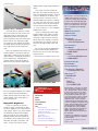
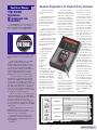
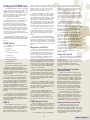
October 2000
Volume 2, No. 10
Dual-Stage
Air Bag Debuts
For the 2001 model year, a supplemental inflatable restraint (SIR) system
featuring dual-stage air bags is
installed in the Oldsmobile Aurora,
Buick LeSabre, Pontiac Bonneville and
Chevrolet Impala and Monte Carlo.
The dual-stage system was
designed to help tailor air bag deployment to the severity of the collision.
To help understand how the dualstage system works, let’s review operation of the model year 2000 singlestage system.
The air bag inflator module, mounted in the steering wheel or in the
instrument panel, consists of a
canister of stored gas, an initiator to heat the stored gas to
expand its volume, and a fabric bag. In a collision, the initiator is electrically energized.
This sets off a chemical reaction which heats the gas and
allows the gas to inflate the
bag. Once the bag is inflated,
it quickly deflates through vent
holes and/or the weave of the
fabric.
An electronic device called
the Sensing and Diagnostic
Module (SDM) located within the vehicle is wired in series with the initiator.
When the SDM detects the conditions
indicating that a collision is occurring,
it completes the circuit to the initiator.
the SDM. For moderate frontal collisions, the stage 1 initiator is energized. For more severe frontal collisions, both stage 1 and 2 initiators are
energized together.
continued on page 2
Dual-Stage System
The dual-stage air bag system adds
several enhancements to this basic
operation. The dual-stage inflator module contains a canister of stored gas,
but has two separate initiators, each
controlled individually by the SDM.
This means that there are two connectors on the module and two sets of
wires between the inflator module and
Contents
Dual-Stage Air Bag Debuts . . . . . . . . . . . . . . . .1
TIS 2000 Updates Broadcast via Satellite . . . . . .3
Common Diagnostics for Keyless Entry Systems . .3
Trunk Release Handles Now Inside All Trunks . . . .4
New Film Protects Vehicles during Transit . . . . . .4
TAC Tips . . . . . . . . . . . . . . . . . . . . . . . . . . . . .5
Tracker Rear Seat Belt Buckle Positioning . . . . . .5
Finding that EVAP Leak . . . . . . . . . . . . . . . . . . .6
Alero Outside Rearview Mirror Vibration . . . . . . .8
Bulletins . . . . . . . . . . . . . . . . . . . . . . . . . . . . .8
Dual stage airbag is identified by having two electrical connections.
1
Service Operations
continued from page 1
deployed dual-stage air bag module as
active.
Deployment Harness J-38826-75
The SDM also is different. In addition to its internal sensor circuitry, the
dual-stage SDM is connected to an
additional electronic frontal sensor
(EFS) mounted in the area of the grille
of the vehicle. The EFS helps judge
the severity of the collision and helps
the SDM decide whether to ignite just
one stage of the inflator module or
two.
Here’s an important fact. When the
inflator module is activated, all of the
stored gas is released. If only the first
stage initiator is energized, the propellant is heated less, and provides a
smaller volume of gas to the bag. If
both the first and second stage initia-
This means that you cannot dispose of a dual-stage module until you
have energized both initiators. The procedure is spelled out in detail in the
service manual. It involves use of a
special Deployment Harness J-3882675, which has two connectors, one for
each initiator. And if you are handling
an instrument panel inflator module,
you must first attach it to the J-39401-B
Deployment Fixture.
If you are deploying a dual-stage
inflator module with stage 1 already
deployed, the movement and noise
caused by stage 2 may be reduced,
because only the initiator is involved;
the stored gas was already used up
when the air bag inflated in the collision.
Be sure to consult the appropriate
service manual sections before performing any service to the dual-stage
air bag system.
– Chuck Wieseckel contributed to this story.
GM TechLink is a monthly magazine for
all GM retail technicians and service
consultants providing timely information
to help increase knowledge about GM
products and improve the performance
of the service department. This magazine is a companion to the GM Edge
publication.
VSSM Communications
Gracemary Allen
Publisher & Editor:
Mark Stesney
GM Service Operations
[email protected]
Technical Editors:
Mark Spencer
[email protected]
1-248-816-3647
Jim Horner
[email protected]
1-248-816-3641
Production Manager:
Marie Meredith
Desktop Publishing:
Greg Szpaichler, MediaWurks
[email protected]
FAX number:
1-248-649-5465
Write to:
Sensing and Diagnostic Module (SDM)
Connectors of the Deployment Harness
J-38826-75 are color-keyed.
tors are energized together, the stored
gas is heated more and provides a
larger volume of gas to the bag. The
whole inflation event takes place in
mere milliseconds.
Deployed Air Bag Service
If you are called on to service a
vehicle in which a dual-stage air bag
has been deployed, you must proceed
with caution. Here’s why. Even though
the deflated air bag will be hanging
from the module, you cannot tell by
looking whether only one or both of
the initiators were employed. It’s possible that the stage 2 initiator is still
active, so you must always treat a
Service
Information
Path
101001001000101
Model Year
Make
Model
Service Manual
Restraints
SIR
- Specifications
- Schematic and Routing Diagrams
- Component Locator
- Diagnostic Information and
Procedures
- Repair Instructions
- Description and Operation
- Special Tools and Equipment
TechLink
PO Box 500
Troy, MI 48007-0500
General Motors service tips are intended for use by professional technicians,
not a "do-it-yourselfer." They are written
to inform those technicians of conditions that may occur on some vehicles,
or to provide information that could
assist in the proper service of a vehicle.
Properly trained technicians have the
equipment, tools, safety instructions
and know-how to do a job properly and
safely. If a condition is described, do not
assume that the bulletin applies to your
vehicle or that your vehicle will have
that condition. See a General Motors
dealer servicing your brand of General
Motors vehicle for information on
whether your vehicle may benefit from
the information.
Inclusion in this publication is not necessarily an endorsement of the individual
or the company.
Copyright© 2000 General Motors Corporation
All rights reserved.
2
Return to page 1
Techline News
TIS 2000
Updates
Broadcast via
Satellite
TIS 2000 Data CD 17 will be the last
CD dealerships receive on a regular
basis to update their TIS 2000 applications. After CD 17, TIS 2000 will be
Common Diagnostics for Keyless Entry Systems
GM uses four different Keyless Entry systems:
- Keyless Entry A with
a dedicated receiver
module that does not
communicate with the
Body Control Module or
the Tech 2 tool.
- Keyless Entry C with
a dedicated module and
Class 2 serial data communicating with the BCM
and other modules.
- Keyless Entry X with
a dedicated module and a
keyless entry serial data
line communicating with
the BCM only.
The Keyless Entry
Inoperative table in all of
the service manuals will
start off by verifying the
customer’s complaint.
You should also read the
description and operation
of this vehicle’s Keyless
Entry system to insure
that you are testing the
system operation correctly. Next, it will ask you to
verify that the customer
is using the correct fob
for this vehicle.
- Keyless Entry UpIntegrated with the
receiver integrated
into the BCM.
updated via broadcasts through the GM
ACCESS satellite communications system.
With the broadcasts, the TIS 2000
application data, including Service
Programming System and the Tech 2,
will be updated automatically every two
weeks. This will provide dealerships
with up-to-date calibration and VIN information while eliminating the need to
load TIS 2000 Data CDs to the GM
ACCESS file server in the dealership.
In order to prepare for the satellite
broadcasts, it is important that all GM
ACCESS TIS 2000 users load Data CD
17 promptly. The updates that will be
broadcast to the GM ACCESS server will
build off of the data that is on CD 17. If
the dealership’s server is not updated
with CD 17, the satellite broadcasts will
not be received. Data CD 17 also should
be retained for backup purposes.
GM also
uses a large
number of
Keyless
Entry
Transmitters
(fobs),
depending on platform body styles. A common diagnostic strategy
has been developed to
save time in diagnosis.
This diagnostic strategy
will be similar for all
Keyless Entry systems
and will be tailored for
each service manual to
the exact vehicle system
and wiring for that vehicle line.
In
multiple
vehicle
families,
your customer may have a fob
that looks correct for the
vehicle but is different
internally and may not
work. The wrong fob will
pass on the J-43241
Keyless Entry Tester but
will not synchronize or
program to the vehicle.
If you are using the
correct fob for this vehicle, the diagnostic then
instructs you to test the
fob using the J-43241
Keyless Entry Tester to
find a dead or weak battery, sticking or inoperative buttons, or a dead
transmitter due to internal electronic failure. The
next step will instruct
you to try to synchronize
the fob to the vehicle by
pressing and holding both the Lock
and Unlock buttons for seven
seconds. If synchronization is
unsuccessful, the
next step is to try
to reprogram the fob
to the vehicle. If the
Keyless Entry system
still has a problem, you
have either a bad module
or a wiring problem. Use
the diagnostic procedures as written to help
you quickly isolate and
repair the condition.
A quick reference
table (sample shown) will
be included in every service manual that allows
you to associate the
physical appearance of a
fob with a part number,
the specific vehicle applications, and RPO numbers.
– Kemel Kulick
When new data is received from the
satellite broadcasts, the TIS 2000 application will automatically look for and pull
down the updates off of the GM
ACCESS server each time the application is opened. The system will display a
message that it is updating the TIS 2000
applications.
Dealerships that do not run the TIS
2000 applications off of the GM
ACCESS system will continue to receive
Data CDs on a monthly basis.
TIS Data CDs also may be sent out
periodically to all users for large data
updates and to act as backups for the
TIS 2000 data.
– Kurt Kilar
3
Return to page 1
Trunk Release
Handles Now
Inside All Trunks
trap resistant
latch and, if
required, a
rear seat
tether kit.
Beginning with the 2001
model year, all GM passenger
cars will now feature new
interior trunk release handles
as standard equipment.
In addition to the new handles, trap resistant trunk kits
are available for previous models. And upcoming on several
2001 models, the trunk
release TrapAlert™ system will
be available.
The two systems are
designed to help prevent a
child from becoming trapped
in the trunk. Some type of
interior trunk release to help
prevent trunk entrapment will
become a Federal requirement
for all motor vehicles beginning in January, 2001.
Trunk Release
Handle
The new trunk release
handle inside the trunk is
located on the trunk latch and
is easily identified. The handle
will glow in the dark following
exposure to a light source,
making it easier to locate
inside the trunk. By simply
pulling the release handle, the
trunk will open from the
inside.
It should be pointed out to
customers that the trunk
release handle is not designed
to be used to tie down the
trunk lid or as an anchor point
Truck release handle now in production
The kit’s
interior
release handle features
two LEDs
that illuminate when
the trunk lid
closes. The
LEDs remain
illuminated
for about one
hour after the
trunk lid is
closed.
The trap
resistant latch in the kit opens
the trunk normally but cannot
be relatched without the user
performing a reset function.
This function is a simple operation for an adult, but is difficult for a young child to perform.
when securing items in the
trunk. Such use of the trunk
release handle could damage
it and prevent proper operation.
The trunk release latch
handle is serviced as one component with the rear compartment lid latch assembly.
The rear seat tether kit is
required if the vehicle is
equipped with a pass-through
to the rear compartment or a
folding rear seat that can be
unlatched from within the passenger compartment without
the use of a key or other locking feature. The tether kit provides a secondary lock of the
seatback.
The trap resistant trunk kit
also requires a rear trunk lid
"ajar" switch. If the vehicle
being retrofitted is not
equipped with a trunk lid ajar
switch, one must be ordered
and installed.
Coming in a few months,
the new automatic TrapAlert™
System will be available. It is
designed to open the trunk
automatically if the electronic
sensor detects motion and a
difference of temperature in
the trunk. More details about
this new system will be coming shortly.
– John Force, Jerry Garfield
Trap Resistant
Trunk Kit
For most 1990-2000 passenger cars with trunks, a
retrofit trap resistant trunk kit
is available. Check bulletin 9908-66-002A for the complete
details on the system’s functions, vehicle modifications
and part numbers required to
install the kit.
The trap resistant trunk kit
includes three main system
components: an LED illuminated interior release handle, a
New Film
Protects Vehicles
during Transit
The paint finishes of the Chevrolet
Monte Carlo, Camaro and Corvette and the
Pontiac Firebird now have additional protection to help maintain their luster. Transseal
Temporary Protective Sheet Film (TPF), a
non-adhesive "breathable" temporary protective film, is being used to protect the paint
finish from mutilation and environmental
damage while the vehicle is being transported and when in vehicle storage at the dealership.
The Transseal TPF acts as a skin or
membrane that allows the paint surface to
breathe or out-gas while protecting the finish. It can be used over sheet metal, TPO,
RIM, SMC and many other types of painted
and molded automotive materials.
When it is applied, the TPF film reacts
like a shrink-wrap packaging material and
conforms to the surface of the vehicle.
It’s recommended to leave the film on
Retrofit trunk kit
the vehicle while it is in dealer inventory
until time of delivery to the customer to protect the paint finish.
Removing TPF Film
TPF film can be removed from the vehicle by using water pressure.
With the vehicle in a wash bay area:
• Wet the vehicle thoroughly with cold
or warm water. Never use hot water to
remove the film. The TPF film is designed to
remove easily from paint surfaces at ambient temperatures between 60 F and 90 F.
• Peel the film off by hand or use water
pressure from a garden hose or a pressure
washer from a manual car wash system.
• It may be efficient to combine the
peeling of the film with one hand while
directing the water with the other.
Place a wire screen over the drain to
stop the film from entering the drainage
system. The Transseal TPF film is classified
as a Class II Non-hazardous Industrial waste
and may be disposed of according to local
city and state disposal regulations. It also
4
may be recycled back into the plastics
industry.
The Paint Finish
The TPF film is designed to leave the
paint finish with a micronized polish. There
should be no need to wax or buff the paint
finish after removing the TPF film.
If a slight haze appears on the paint surface from the TPF film, it can be removed
by washing the vehicle by hand with soap
and water.
If there are any witness marks from the
water after removing the TPF film, park the
vehicle outside and allow the heat from the
sun to warm the paint finish and dry the
vehicle.
Any TPF film residue also may be
removed by using a small amount of the
GM "OptiKleen" windshield washing concentrate solution. If any residue remains,
general household ammonia may be used.
The vehicle should then be thoroughly
rinsed with warm water.
– Gary McAdam
Return to page 1
TAC Tips
2000 Pontiac Grand
Prix DTCs Not in
Service Information
There may be several possible intermittent Vehicle Theft Deterrent (RPO PK3)
DTCs (B3022 B3023 B3024 B3025) and/or
a crank, no start condition exhibited on
some 2000 Pontiac Grand Prix models.
Currently, there is no information about
these DTCs in the Service Information.
These DTCs are B3022, fuel enable
circuit range/performance; B3023, fuel
enable circuit low; B3024, fuel enable circuit high; and B3025, fuel enable circuit
open. When diagnosing these DTCs, keep
in mind that this system is not a Class 2
system. The components consist only of
the VTD module, the PCM and related
wiring.
For any of the above DTCs, disconnect the VTD module connector located
near the base of the steering column.
With the key On, measure the harness
side connector CKT 229 for the 5V/12V
voltage pull up.
If zero volts are measured, check CKT
229 for an open or short to ground. If the
circuit checks out OK, check the connec-
Tracker Rear
Seat Belt Buckle
Positioning
Each seat belt latch plate in every
vehicle is designed to connect only
to the matching buckle. This ensures
that the seat belts are buckled properly. On 1999-2000 Chevrolet Tracker
4-door models, rear seat passengers
may confuse the center and left rear
seat belt buckles, which may lead to
customer questions and unnecessary
parts replacement.
tions at the PCM for
poor contact or
shorts to ground.
Replacing the PCM
is a possible repair correction only if the
circuit and connections are OK.
If 5V/12V are measured, check the
connection at the VTD module (right
where the original disconnect was made)
for poor connections or shorts to ground.
If the connections are OK, replace the
VTD module.
The service information will be corrected shortly.
Lost AMCOR Wheel
Lock Key and
Identification Card
If the wheel lock key and/or identification card for 1994-2001 Chevrolet
Camaro, Corvette and Pontiac Firebird
models and 1994-96 Chevrolet Impala
models has been lost, a replacement can
be obtained in either of following ways:
1. Fill out and send in the registration
card with a check for $10 to:
AMCOR Wheel Locks
12955 Inkster Rd.
Livonia, MI 48150
gray color. Plus, all center rear seat
belt service replacement parts for the
1999, 2000 and 2001 model years
will be light gray in order to differentiate them from the left and right rear
seat belt components.
In the rear seat floor pan, the center buckle is located outboard of the
left buckle and the center latch plate
is located outboard of the right buck-
Allow 5-7 days from the receipt of the
order. AMCOR will return the I.D. Card
with the key.
2. Send a fax with the wheel lock
identification number, VISA or MC
account number and expiration date,
name, ship to address and a daytime
phone number with area code to: 734266-6927. There is a $1.50 process fee
for faxed orders.
Shipping costs are $11.50 for standard
shipping and $26.50 for express orders.
Customers who have lost their identification card should call AMCOR directly
for assistance with finding a GM dealer in
their area that has AMCOR master key
sets. AMCOR can be reached at 734-4588920, 8:30 a.m. - 4:30 p.m. Eastern time.
Regal and Monte
Carlo Headliner Sag
The interior roof trim panel (headliner)
may sag at the rear glass on some 200001 Buick Regals and Chevrolet Monte
Carlos due to insufficient adhesive. Add
Velcro® or adhesive to resecure the trim
panel. Do not replace the trim panel.
– GM Technical Assistance
le. If the latch plate or buckles are
ever removed, they must be reinstalled correctly in order to maintain
their effectiveness.
For more details and additional
graphics illustrating the correct positions of each of the rear seat belt
buckles on 1999-2000 Trackers,
check out bulletin 99-09-40-002A.
– Donald B. Sherman
The center rear seat belt buckle
on the Tracker is located outboard of
the left buckle when the buckles are
not in use. When in use, the center
and left seat belt buckles cross over
each other.
To make it easier to identify the
rear seat belt buckles, the center
buckle is clearly marked "CENTER"
on the buckle cover and on the
matching center rear latch plate.
Beginning with the 2001 model
year, the center rear seat belt buckle
cover has been changed to a light
5
Return to page 1
Finding that EVAP Leak
A leaking Evaporative Emissions (EVAP)
system can produce more hydrocarbons in
a day than what is emitted from the
tailpipe of a properly operating vehicle during the consumption of a complete tank of
fuel. Catching those leaks is one of the
main reasons behind OBD II.
In the past, many leaks were often
caused by owners who, for example, did
not fully tighten the fuel cap. Now, as
those large leaks decrease as owners
become more educated about the EVAP
system, small leaks pose a greater challenge to technicians. Most small leaks are
hard leaks in the system, which cannot be
corrected by software calibration changes.
Currently, there are no EVAP software
issues or new calibrations being developed
to address leaks.
Repairing EVAP conditions takes an
understanding of the EVAP system and the
related tools needed to troubleshoot EVAP
DTCs.
EVAP Basics
The EVAP system includes the following components:
• fuel tank
• EVAP vent valve
• fuel pipes and hoses
• fuel fill cap
• EVAP vapor pipes
• EVAP purge pipes
• EVAP canister
• EVAP canister purge valve
From the early 1980s until the advent
of OBD II, the system was virtually
unchanged. A canister filled with charcoal
(or in later years, activated carbon) was
designed to absorb and retain hydrocarbon
vapors emanating from the fuel tank or the
carburetor bowl.
A pulse-width-modulated purge solenoid controlled engine vacuum supply to
the canister. When the conditions were
correct, usually under certain high throttle
angles and engine RPM in a closed loop,
the ECM would actuate the purge solenoid. The vacuum applied to the canister
would pull fresh air into the canister
through an integral vent, forcing the hydrocarbons into the intake air charge and burning them in the engine during normal combustion.
The fresh air vent on the canister also
prevented system overpressure when the
vehicle was parked for long periods. The
fuel cap also provided an alternate vent
path if there was a vent failure of both vacuum and pressure.
OBD II
When OBD II was introduced, some
components were added to the EVAP system to aid the PCM in system diagnostics.
The first addition was a vent solenoid,
which provided a way to control the vent
path in order to test for leaks. Unlike the
purge solenoid, it is not pulse-width-modulated. Its valve is normally open to atmospheric air when the solenoid is off. The
PCM turns the solenoid on to close the
valve when running system tests.
Another new OBD II component was
the fuel tank pressure sensor. It is typically
mounted on or near the fuel tank pump
and sender module. This sensor is a threewire strain gage similar in operation and
appearance to a manifold absolute pressure (MAP) sensor. However, these parts
are not calibrated to the same bias and are
not interchangeable. The PCM uses the
pressure sensor to detect pressure or vacuum in the fuel system in various tests.
In addition, the fuel level sensor provides a direct input for the PCM that is
used to determine if the fuel tank level is
appropriate for testing (typically 15% to
85%).
Fuel caps also changed with OBD II.
Venting characteristics under pressure and
vacuum were changed to make the caps
fall within testing parameters. An aftermarket fuel cap may not conform to these test
standards, and may be the cause of a set
DTC.
Diagnosis and DTCs
With all of your diagnosis, begin with
the most likely source of leaks, the connections between system lines and components such as the connections at the
canister. Also pay close attention to the
seam on the filler neck and the o-ring at
the fuel tank sending unit. Check for
kinked or incorrectly routed vacuum lines
as well. Take diagnosis one step at a time
and systematically test from one end of
the system to the other. Isolate each part
of the system. Also check any parts that
were removed during other repairs that
may have created a leak.
When following the diagnostic tables in
the service manuals for each EVAP DTC,
remember that the tables are based on
current conditions. If there is an intermittent leak without a current DTC set, review
the "System Description" along with the
"Conditions For Setting the DTC" and the
"Diagnostic Aids."
Many times, EVAP DTCs are not current. But this doesn’t mean they should be
cleared immediately. Always try to duplicate the condition. If you can’t, don’t clear
the DTCs. They usually will offer some
insight into the condition.
Reviewing the Fail Records vehicle
mileage since the last diagnostic test
failed, for example, may indicate how often
the condition that caused a DTC to set
occurs. If there is a high amount of
mileage between failures, chances are
there is a very small leak in the system.
EVAP System Tests
Before the PCM can run the EVAP system tests, certain parameters must be
met, such as an appropriate fuel tank level,
ambient temperature, coolant temperature,
etc. (See the service manual for all parameters).
In the EVAP test cycle, the PCM first
6
looks for excess vacuum buildup during
normal canister purging. Normal canister
purging requires the vent solenoid to be
off (open to vent) and the purge solenoid
to be on (applying vacuum).
Simultaneously, another test run by the
PCM during normal purging monitors the
oxygen sensors for a fuel trim shift toward
rich, indicating sufficient loading of the canister. These tests are the setup for the leak
tests.
When the PCM determines that the
canister was not sufficiently loaded during
purge, it will turn on the vent solenoid. A
blocked vent path is anticipated to create a
vacuum condition in the fuel tank. If it does
not, a large leak is detected and DTC
P0440 is set or a gross leak is detected
and DTC P0446 is set.
If the PCM sees the vacuum build in
the system, it will turn off the purge solenoid and monitor the fuel tank pressure
sensor for vacuum decay or vacuum
increase. Vacuum decay indicates a small
leak above a calibrated amount, and an
increase in vacuum would mean a purge
solenoid problem.
The testing conditions vary slightly for
EVAP systems from vehicle to vehicle, so
consult the service manual under
"Conditions for Running the DTC" for each
set DTC for further clarification of the
enable criteria.
Using the Tech 2
The Tech 2 is the most powerful and
essential tool for EVAP system diagnostics.
Under Powertrain Special Functions, the
EVAP System menu contains essential outputs for testing the system. The four most
common are Purge Solenoid, Vent
Solenoid, System Performance and Seal
System.
Purge Solenoid and Vent
Solenoid Tests
Purge Solenoid and Vent Solenoid are
simply tests that allow you to actuate each
solenoid individually. If you are working on
a vehicle with a DTC P0446 – EVAP canister vent blocked, for example, what would
you do to verify the condition is present?
With the vehicle running, activating the
Purge Solenoid test should not cause the
fuel tank pressure to go excessively into
vacuum. If it does, you have verified the
presence of the condition and can utilize
this test after removing various vent path
components to help aid in diagnostics.
The Vent Solenoid test can be similarly
used to test the purge solenoid. A DTC
P1441 – EVAP system flow during nonpurge, can be verified with the vehicle running and by turning on the vent solenoid.
Assuming that the purge solenoid is off, the
tank pressure should not be decreasing.
System Performance Test
Using other Tech 2 tests, you can
recreate the testing performed by the
PCM. Here is another example. On a vehicle with a DTC P0440 – EVAP system large
leak detected, your first instinct should not
be to tighten the fuel cap, but instead to
use the Tech 2.
Return to page 1
required to test components and component fittings for a small inaudible leak.
Soap should be chosen carefully, as
any that contain ammonia may corrode
metal parts. Rinse any area tested with
soapy water with clean water afterwards.
Fuel Cap Adapters
If it’s necessary to raise the vehicle, a
fuel cap adapter may be used. There are
currently four different fuel cap adapters –
J-41415-10, -20, -30 and -40 -- that fit the
various types of cap designs.
From the EVAP System menu, select
System Performance. This test will actuate
both the purge and the vent solenoids.
What’s the anticipated result with the vehicle running? The open purge solenoid and
closed vent solenoid should create vacuum
in the tank at a level high enough to abort
the testing on the Tech 2. If the Tech 2
does not abort the testing at this point,
check for a loose fuel cap. If you tighten
the cap and then the Tech 2 aborts the
test, you have found the source of the
DTC P0440.
Seal System Test and the
EVAP Diagnostic Station
The last test found on the Tech 2, Seal
System, is used in conjunction with the J41413 EVAP Diagnostic Station. This tool
consists of a sturdy green cart outfitted
with two gages and a set of hoses. The
bottle installed on the cart contains dry
nitrogen gas, a non-toxic inert gas (79% of
what you are breathing right now is nitrogen) that is safe to use to pressurize the
fuel system. An in-line regulator keeps the
nitrogen pressure typically less than 30
inches of water pressure (approximately 2
psi).
The black hose attached to the cart is
for a built-in vacuum gage on the right side
of the top panel. The blue hose is designed
to go into your shop ventilation system to
carry the fumes away from the work area
upon system depressurization. The red
hose has the service fitting on the end to
be attached to the vehicle’s service port for
diagnostics.
Be sure to check the J-41413
Diagnostic Station for leaks before beginning any diagnostics. Turn on the nitrogen
bottle and attach the red service hose to
the test port. Next, twist the dial on the
face panel to the 9 o’clock position to
charge the hose with pressure. Turn the
dial to the 12 o’clock position for pressure
hold and watch to see if the pressure
degrades for a period of a few minutes. If
pressure degrades, the diagnostic station
needs to be repaired.
The theory of testing for leaks is simple. Using the Tech 2 Seal System test, the
PCM actuates the vent solenoid and prevents the actuation of the purge solenoid
to prepare the system for pressure testing.
Pressure is used rather than vacuum to aid
in locating the leak. Pressure leaks are outwardly audible or may be detected with a
soapy water solution. Snoop Liquid Leak
Detect from Kent-Moore, J-41365, or
equivalent may be used.
Using the diagnostic station, apply a
small amount of pressure (typically 5 to 7
inches of water column pressure). This is a
process that can vary in time depending on
the amount of fuel in the tank. If the system does not pressurize, locate the leak
using the J-41416 Ultrasonic Leak Detector
and repair immediately. The pressure apply
may be modulated by turning the dial on
the Diagnostic Station toward the 9 o’clock
position from the 12 o’clock position.
Watch the fuel tank pressure reading on
the Tech 2 to see if it is approaching the
pressure gage reading on the left side of
the J-41413 panel. After flow is stopped,
pressure readings will stabilize within a
few seconds. Add more pressure as necessary to reach the desired testing level.
The next step is to watch for any decay
of pressure. The general area of a rapid
pressure loss typically may be located with
the ultrasonic leak detector. This device is
sensitive to specific sounds associated
with air leaks. Be careful to use this tool in
an area that is free of other sources for air
noise, such as leaky shop lines or fittings,
air tools, spray cans, etc.
Soapy Water Testing
Leaks associated with DTC P0442 –
EVAP small leak, may require a different
approach. Once pressure decay is verified,
a trigger bottle of soapy water may be
7
Fuel cap adapters have become necessary in testing for one other reason. With
the advent of ORVR (On-board Refueling
Vapor Recovery), the fuel tank and filler
neck architecture have changed. No longer
is there a vent tube running parallel to the
filler tube. The filler tube is now much
smaller to provide a seal preventing the
loss of hydrocarbons during fill. The fuel
vapors are sucked down the neck by a
venturi effect created by the rushing fuel
and collected by the EVAP Canister. Also
integrated in the filler design is an anti-spitback check valve in the base of the filler
neck at the tank.
During pressurized system leak tests
using the vehicle’s underhood service port,
testing pressure may never make it to the
filler neck due to the level of fuel in the
tank and the anti-spitback valve. The valve
creates a positive seal under pressure,
whereas under vacuum (the way it is tested by the PCM) the valve allows for ventilation of the system and testing fails.
Therefore, a technician not using a fuel cap
adapter (typically, adapter J-41415-40 is
used on ORVR systems) may never see a
pressure decay if the leak is in the filler
neck or fuel cap. Testing with the
Diagnostic Station through a fuel cap
adapter can help to find these leaks.
Confirming Repairs
Once the leak is found and repaired,
another noteworthy Tech 2 feature under
Powertrain Special Functions is Service
Bay Tests – EVAP System. This test function helps the PCM run the diagnostics for
the various EVAP system DTCs more
quickly, broadening the enable criteria for
purposes of verifying the repair of the vehicle. This is a critical step in preventing an
EVAP related comeback.
Keep in mind that two consecutive
passes are needed when confirming a
repair. If it passes once in the service
department, it may not pass again in the
owner’s driveway.
As with all repairs, checks should be
made for any applicable bulletins and calibrations that address EVAP conditions.
Presently, however, there are not any new
calibrations being developed for current
EVAP systems.
EVAP system leaks can be hard to find.
But if you know what causes each DTC to
set, and understand how to use the tools
available to you, you’ll be well on your way
to expertly diagnosing EVAP conditions.
– Craig Blake
Return to page 1
Bulletins –
September 2000
This review of service bulletins released
through mid-September lists the bulletin number,
superseded bulletin number (if applicable), subject and models.
GENERAL INFORMATION:
00-00-89-018; July, 2000 Bulletin Summary;
2001 and Prior Passenger Cars and Trucks
00-00-89-019; New Electrical Relay Labor
Operation Numbers; 2001 and Prior Passenger
Cars and Trucks
00-00-89-020; September, 2000 Labor Time
Guide Updates; 1996-2001 Passenger Cars and
Trucks
00-00-89-021; Cross-line Warranty; 2001 and
Prior Passenger Cars and Trucks
HVAC:
99-01-39-006A; Replaces 99-01-39-006;
Production Changes to A/C System
Components, Revisions to Reduce Possible
Passenger Compartment Hiss Noise and New
Charging Guidelines; 1999 Chevrolet Corvette
00-01-37-003; Delphi®-Harrison and Denso
A/C Compressor Usage; 2000-2001 Chevrolet
and GMC C/K Pickup Models With 4.8L, 5.3L or
6.0L Gen III Gas Engine (VINs V, T, U – RPOs
LR4, LM7, LQ4)
00-01-38-006; Essential Tool J 43600 ACR
2000; 1993-2001 Passenger Cars and Trucks
(Except Medium Duty Trucks)
SUSPENSION:
00-03-10-003; Replaces 60-05-02; General
Motors Tire Warranty; 1996-2001 Passenger
Cars and Light Duty Trucks (Except Saturn
Models)
BRAKES:
00-05-22-007; Reduced Brake Pad/Lining
Life (Install New Brake Booster Pushrod Lever);
1997-98 Chevrolet and GMC T-Series Medium
Duty Tilt Cab Models With Hydraulic Brakes
(RPO JE3) Built Prior to January 28, 1998
00-05-23-005; Availability of Rear Wheel
Mud Flaps; 1999-2000 Chevrolet and GMC C/K
Pickup Models (Silverado and Sierra)
ENGINE/PROPULSION SYSTEM:
00-06-01-016; Enhanced Aluminum Engine
Component Thread Repair Process; 1993
Cadillac Allante, 1993-2001 Cadillac Eldorado and
Seville, 1994-1999 Cadillac DeVille Concours,
1996-2001 Cadillac DeVille, 2000-2001 Cadillac
DeVille Touring, 1997-2001 Chevrolet Corvette,
1998-2001 Chevrolet Camaro, 1995-2001
Oldsmobile Aurora (V8), 1999-2001 Oldsmobile
Intrigue, 2001 Oldsmobile Aurora (V6), 19982001 Pontiac Firebird, With 2.2L, 3.5L, 4.0L,
4.6L or 5.7L Engine (VINs F, H, C, 9, Y, G, S –
RPOs L61, LX5, L 47, L37, LD8, LS1, LS6)
00-06-01-018; Growl/Moan Noise During
Sharp Left Turn (Modify Engine Mount
Stamping): 2000 Chevrolet Cavalier, 2000
Pontiac Sunfire, With 2.2L Engine (VIN 4 – RPO
LN2)
00-06-02-006; Replaces 73-62-14; DEXCOOL® Engine Coolant Information; 2001 and
Prior Passenger Cars and Trucks
00-06-04-025A; Replaces 00-06-04-025; ABS
Light On at High Speeds (Above 70 mph or 113
km/h), Code C0237 Set (Install New PCM); 2000
Chevrolet and GMC S/T Pickup Models With
2.2L Engine (VINs 4, 5 – RPOs LN2, L43) and
4L60-E Automatic
Transmission (RPO M30)
00-06-04-028;
Bang/Slosh From Rear of Vehicle (Install Fuel
Tank Insulators); 2000 Buick Century and Regal,
2000 Chevrolet Impala and Monte Carlo
00-06-04-030; Revised Fuel Pressure
Operating Range; 2001 Buick LeSabre, Park
Avenue and Regal, 2001 Chevrolet Impala and
Monte Carlo, 2001 Pontiac Bonneville and Grand
Prix, With 3.8L Engine (VIN K – RPO L36)
00-06-04-033; Enhanced Emission
Inspection Maintenance Program – Emissions
Diagnostic Manual for OBD II Vehicles; 19962000 Passenger Cars and Trucks
00-06-04-037; Service Engine Soon (SES)
Light On With DTCs P0716 and/or P0717 Set
(Repair Input Speed Sensor Wiring at Transaxle
Wiring Pass-thru Connector); 2000-2001
Chevrolet Cavalier and Malibu, 2000-2001
Oldsmobile Alero, 2000-2001 Pontiac Grand Am
and Sunfire, 2000 Toyota Cavalier
00-06-04-038; Unwanted Switch to Gasoline,
Fuel Indicator Lamp (FIL) Inoperative, Cooling
Fan Inoperative, Engine Running Hot and/or
Overheating (Replace Cooling Fan/CNG Fuse);
2000 Chevrolet Cavalier With 2.2L Engine (VIN 4
– RPO LN2) and Bi-Fuel (CNG) (RPO KL6)
TRANSMISSION/TRANSAXLE:
00-07-29-001; 4-3 Downshift Gear Clash, 1-2
Upshift Gear Clash When Cold (Replace Affected
Gear, Synchronizer Ring, Synchronizer Assembly
and Transmission Fluid); 1999-2000 Chevrolet
Tracker With 5-Speed Manual Transmission (RPO
M59)
00-07-30-002A; Replaces 00-07-30-002;
Slips, Harsh Upshift or Garage Shifts, Launch
Shudders, Flares, Erratic Shifts and Intermittent
Concerns, DTC P1811 or P0748 Set (Replace
Pressure Control Solenoid Valve Assembly);
1999-2000 Buick LeSabre, Park Avenue/Ultra,
Regal and Riviera, 1999 Chevrolet Lumina,
Monte Carlo and Venture, 1999 Oldsmobile
Eighty-Eight, Intrigue and Silhouette, 1999
Pontiac Bonneville, Grand Prix and Montana,
With Hydra-Matic 4T65-E (RPO MN3, MN7 or
M15) and 3.4L, 3.5L or 3.8L Engine (VINs E, H,
K, 1 – RPOs LA1, LX5, L36, L67)
00-07-30-015; Revised DTC Tables for P0716
and P0717 (Section 7 Automatic Transmission);
1998-2000 Chevrolet and GMC C/K Models and
G Van With Hydra-Matic 4L80-E Automatic
Transmission (RPO MT1)
00-07-30-016; Removal of the PWM Filter
From the Spacer Plate – 4T40E/4T45E Automatic
Transmission; 1998-2000 Chevrolet Cavalier and
Malibu, 1998-1999 Oldsmobile Cutlass, 19992000 Oldsmobile Alero, 1998-2000 Pontiac
Sunfire, 1999-2000 Pontiac Grand Am, With
4T40E or 4T45E Automatic Transmission (RPOs
MN4, MN5)
00-07-31-001; Clutch Noisy, Slipping or
Inoperative (Replace Clutch Release Bearing);
1990-2000 Chevrolet and GMC C6-7
Conventional Medium Duty Trucks, 1993-2000
Chevrolet and GMC B7 School Buses, With Gas
or Diesel Engine and Spicer 310 mm Clutch
(RPO MRJ), Valeo 13 Inch Clutch (RPO MPJ), or
Midland Lipe Clutch Built Prior to May 24, 2000
and VIN Breakpoints
BODY AND ACCESSORIES:
99-08-48-001A; Replaces 99-08-48-001;
Wind Noise from Body Side Quarter Window
(Replace Body Side Quarter Window Assembly);
1999-2000 Chevrolet and GMC C/K Extended
8
Cab Pickup Models (Silverado and Sierra) Built
Prior to February 1, 2000
00-08-49-009; Addition of DTC B2961
Diagnostics; 2000 Chevrolet and GMC C/K
Pickup and Utility Models, 2000 Chevrolet S/T
Models and M/L Vans, 2000 Oldsmobile Bravada
00-08-51-001; Outside Rear View Mirror
Housing Turns Chalky/Dull (Color/Clear Coat
Mirror); 1998-2000 Buick Century, Park Avenue
and Regal, 1998-2000 Chevrolet Cavalier,
Lumina, Malibu, Metro, Monte Carlo, Prizm,
Tracker and Venture, 2000 Chevrolet Impala,
1998-2000 Oldsmobile Intrigue and Silhouette,
1999-2000 Oldsmobile Alero, 1998-2000 Pontiac
Bonneville, Grand Am, Sunfire and Trans Sport,
1998-2000 Chevrolet and GMC C/K, S/T Models
and M/L Van, 1998-2000 Oldsmobile Bravada
00-08-52-004; Intermittent Operation of
Remote Keyless Entry System (Replace
Instrument Panel Cluster); 2000 Chevrolet
Impala and Monte Carlo
00-08-61-002; Engine Mount Crossmember
Cracking (Replace Crossmember and Fasteners);
1993-2000 Chevrolet and GMC B6-7 Medium
Duty School Bus Models With 3116/3126
Caterpillar® Diesel Engine
00-08-62-002; Brush Guard Removal; 1999
Chevrolet Tahoe Utility Models With Off-Road
Chassis Package (RPO Z71)
Alero Outside
Rearview
Mirror
Vibration
The outside rearview mirror
on some 1999-2001 Oldsmobile
Alero models may vibrate at all
speeds. There also may be
excessive wind noise coming
from the "A" pillar area of the
vehicle.
The vibration and windnoise
may be caused by the breakaway
mirror not being properly seated
at the mirror patch. Cycle the
mirror housing forward and rearward to allow the mirror to snap
back. Observe the mirror housing. It should be flush to the mirror patch and fully seated around
the circumference.
In addition, the mirror glass
retainer may not be fully seated
into the power mirror motor
assembly, or into the retainer on
manual mirrors. Press the center
area of the reflective surface to
ensure that the mirror glass
retainer is fully seated (snaps in
place) in the power mirror motor,
or in the mirror retainer on manu al mirrors.
– Darryl Butler
Return to page 1