1
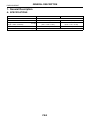
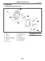
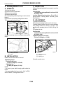
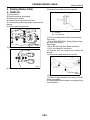
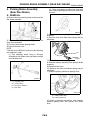
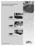
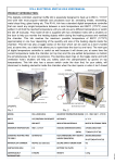
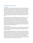
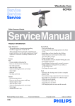
2001 IMPREZA SERVICE MANUAL
QUICK REFERENCE INDEX
CHASSIS SECTION
This service manual has been prepared
to provide SUBARU service personnel
with the necessary information and data
for the correct maintenance and repair
of SUBARU vehicles.
This manual includes the procedures
for maintenance, disassembling, reassembling, inspection and adjustment of
components and diagnostics for guidance of experienced mechanics.
Please peruse and utilize this manual
fully to ensure complete repair work for
satisfying our customers by keeping
their vehicle in optimum condition.
When replacement of parts during
repair work is needed, be sure to use
SUBARU genuine parts.
FRONT SUSPENSION
FS
REAR SUSPENSION
RS
WHEEL AND TIRE SYSTEM
WT
DIFFERENTIALS
DI
TRANSFER CASE
TC
DRIVE SHAFT SYSTEM
DS
ABS
ABS
ABS (DIAGNOSTICS)
ABS
BRAKE
BR
PARKING BRAKE
PB
POWER ASSISTED SYSTEM
(POWER STEERING)
PS
All information, illustration and specifications contained in this manual are
based on the latest product information
available at the time of publication
approval.
FUJI HEAVY INDUSTRIES LTD.
G1830GE5
PARKING BRAKE
PB
1.
2.
3.
4.
5.
Page
General Description ....................................................................................2
Parking Brake Lever....................................................................................6
Parking Brake Cable ...................................................................................7
Parking Brake Assembly (Rear Disc Brake) ...............................................9
General Diagnostic Table..........................................................................12
GENERAL DESCRIPTION
PARKING BRAKE
1. General Description
A: SPECIFICATIONS
Model
Type
Effective drum diameter
Lining dimensions
(length × width × thickness)
Clearance adjustment
Lever stroke
mm (in)
mm (in)
notches/N (kgf, lb)
Rear drum brake
Rear disc brake
Mechanical on rear brakes, drum in disc
228.6 (9)
170 (6.69)
218.8 × 35.0 × 4.1
162.6 × 30.0 × 3.2
(8.61 × 1.378 × 0.161)
(6.40 × 1.181 × 0.126)
Automatic adjustment
Manual adjustment
7 to 8/196 (20, 44)
PB-2
GENERAL DESCRIPTION
PARKING BRAKE
B: COMPONENT
1. PARKING BRAKE (REAR DISC BRAKE)
B4M1127A
(1)
(2)
(3)
(4)
(5)
(6)
(7)
(8)
(9)
Back plate
Retainer
Spring washer
Lever
Parking brake shoe (Primary)
Parking brake shoe (Secondary)
Strut spring
Strut
Shoe guide plate
(10)
(11)
(12)
(13)
(14)
(15)
(16)
(17)
Primary return spring
Secondary return spring
Adjusting spring
Adjuster
Shoe hold-down cup
Shoe hold down spring
Shoe hold down pin
Adjusting hole cover
PB-3
Tightening torque: N·m (kgf-m, ft-lb)
T: 53 (5.4, 39)
GENERAL DESCRIPTION
PARKING BRAKE
2. PARKING BRAKE CABLE
B4M0705B
(1)
(2)
(3)
(4)
(5)
(6)
Parking brake lever
Parking brake switch
Lock nut
Adjusting nut
Equalizer
Bracket
(7)
(8)
(9)
(10)
Clamp
Parking brake cable RH
Cable guide
Clamp (Rear disc brake model
only)
(11)
Parking brake cable LH
PB-4
Tightening torque: N·m (kgf-m, ft-lb)
T1: 5.9 (0.60, 4.3)
T2: 18 (1.8, 13.0)
T3: 32 (3.3, 24)
GENERAL DESCRIPTION
PARKING BRAKE
C: CAUTION
• Wear working clothing, including a cap, protective goggles, and protective shoes during operation.
• Remove contamination including dirt and corrosion before removal, installation or disassembly.
• Keep the disassembled parts in order and protect them from dust or dirt.
• Before removal, installation or disassembly, be
sure to clarify the failure. Avoid unnecessary removal, installation, disassembly, and replacement.
• Be careful not to burn your hands, because each
part on the vehicle is hot after running.
• Use SUBARU genuine grease etc. or the equivalent. Do not mix grease etc. with that of another
grade or from other manufacturers.
• Be sure to tighten fasteners including bolts and
nuts to the specified torque.
• Place shop jacks or safety stands at the specified
points.
• Apply grease onto sliding or revolution surfaces
before installation.
• Before installing O-rings or snap rings, apply sufficient amount of grease to avoid damage and deformation.
• Before securing a part on a vice, place cushioning material such as wood blocks, aluminum plate,
or shop cloth between the part and the vice.
• Keep grease etc. away from parking brake
shoes.
PB-5
PARKING BRAKE LEVER
PARKING BRAKE
2. Parking Brake Lever
C: INSPECTION
A: REMOVAL
While pulling parking brake lever upward, count the
notches.
1) Lift-up the vehicle.
2) Remove rear tire and wheel.
3) Remove rear cushion.
4) Remove console box.
5) Loosen parking cable adjusting nut and console
bracket.
6) Disconnect connector parking brake switch.
7) Remove parking brake lever.
Lever stroke:
7 to 8 notches when pulled with a force of 196
N (20 kgf, 44 lb)
Incorrect, adjust the parking brake. <Ref. to PB-11,
ADJUSTMENT, Parking Brake Assembly (Rear
Disc Brake).>
D: ADJUSTMENT
1) Remove console cover.
2) Forcibly pull parking brake lever 3 to 5 times.
3) Adjust parking brake lever by turning adjuster
until parking brake lever stroke is set at 7 to 8
notches with operating force of 196 N (20 kgf, 44
lb).
4) Tighten lock nut.
BR0029
8) Unbend parking brake lever pawls and remove
cable.
Lever stroke:
7 to 8 notches when pulled with a force of 196
N (20 kgf, 44 lb)
Tightening torque (Lock nut):
5.9 N·m (0.60 kgf-m, 4.3 ft-lb)
S4M0471A
BR0054
(1) Parking brake lever
(2) Cable
(1) Parking brake lever
(2) Lock nut
(3) Adjusting nut
B: INSTALLATION
Install in the reverse order of removal.
5) Install console cover.
Tightening torque:
Parking brake lever;
18 N·m (1.8 kgf-m, 13.0 ft-lb)
Adjusting nut;
5.9 N·m (0.6 kgf-m, 4.3 ft-lb)
NOTE:
• Be sure to pass cable through guide inside the
tunnel.
• Be sure to adjust the lever stroke. <Ref. to PB-6,
ADJUSTMENT, Parking Brake Lever.>
PB-6
PARKING BRAKE CABLE
PARKING BRAKE
3. Parking Brake Cable
9) Remove inner cable end from equalizer.
A: REMOVAL
1) Lift-up vehicle.
2) Remove rear tires and wheels.
3) Remove rear cushion.
4) Remove console box from front floor.
5) Loosen parking cable adjusting nut and console
bracket.
6) Remove parking brake lever.
S4M0473A
(1) Equalizer
(2) Inner cable end
BR0029
7) Roll up floor mat and remove clamps.
10) Pull out parking brake cable from rear brake.
Disc brake
<Ref. to PB-9, REMOVAL, Parking Brake Assembly (Rear Disc Brake).>
Drum brake
<Ref. to BR-48, Rear Drum Brake Assembly.>
11) Pull out clamp from rear brake.
12) Remove bolt and bracket from trailing link
bracket.
13) Remove bolt and clamp from rear floor.
BR0030
8) Remove equalizer cover.
G4M0433
14) Detach grommet from rear floor.
15) Remove cable assembly from cabin by forcibly
pulling it backward.
16) Detach parking brake cable from cable guide at
rear trailing link.
PB-7
PARKING BRAKE CABLE
PARKING BRAKE
B: INSTALLATION
C: INSPECTION
Install (new) parking brake assembly in the reverse
order of removal.
Check the removed cable and replace if damaged,
rusty, or malfunctioning.
1) Check for smooth operation of the cable.
2) Check the inner cable for damage and rust.
3) Check the outer cable for damage, bends, and
cracks.
4) Check the boot for damage, cracks, and deterioration.
NOTE:
• Be sure to pass cable through cable guide inside
the tunnel.
• Be sure to adjust the lever stroke. <Ref. to PB-6,
ADJUSTMENT, Parking Brake Lever.>
PB-8
PARKING BRAKE ASSEMBLY (REAR DISC BRAKE)
PARKING BRAKE
4. Parking Brake Assembly
(Rear Disc Brake)
(2) If disc rotor seizes up within hub, drive disc
rotor out by installing an 8-mm bolt in holes B on
the rotor.
A: REMOVAL
1) Remove the two mounting bolts and remove the
disc brake assembly.
G4M0383
G4M0412
2) Suspend the disc brake assembly so that the
hose is not stretched.
3) Pull down and release parking brake.
4) Remove the disc rotor.
5) Remove shoe return spring from parking brake
assembly.
6) Remove front shoe hold down spring and pin
with pliers.
NOTE:
If the disc rotor is difficult to remove try the following
two methods in order.
(1) Turn adjusting screw using a slot-type
screwdriver until brake shoe gets away enough
from the disc rotor.
BR0055
7) Remove strut and strut spring.
8) Remove adjuster assembly from parking brake
assembly.
9) Remove brake shoe.
10) Remove rear shoe hold-down spring and pin
with pliers.
11) Remove parking cable from parking lever.
S4M0463A
(1)
(2)
(3)
(4)
Adjusting screw
Cover (rubber)
Slot-type screwdriver
Back plate
B4M1774B
(1) Parking brake cable
(2) Parking brake lever
12) Using a standard screwdriver, raise retainer.
Remove parking lever and washer from brake
shoe.
PB-9
PARKING BRAKE ASSEMBLY (REAR DISC BRAKE)
PARKING BRAKE
B: INSTALLATION
CAUTION:
Be sure lining surface is free from oil contamination.
Brake grease:
Dow Corning Molykote No. 7439 (Part No.
725191460)
1) Apply brake grease to the following places.
• Six contact surfaces of shoe rim and back plate
packing
• Contact surface of shoe wave and anchor pin
• Contact surface of lever and strut
• Contact surface of shoe wave and adjuster assembly
• Contact surface of shoe wave and strut
• Contact surface of lever and shoe wave
2) Install in reverse order of removal.
CAUTION:
• Use new retainers and clinch them when installing brake shoes to levers.
• Ensure that parking lever moves smoothly.
• Do not confuse left parking lever with right
one.
• Do not confuse left strut with right one.
NOTE:
Ensure that adjuster assembly is securely installed
with screw in the left side, facing vehicle front.
S4M0462A
(1)
(2)
(3)
(4)
(5)
(6)
(7)
(8)
(9)
Back plate
Shoe guide plate
Retainer
Spring washer
Lever
Primary shoe return spring (Blue)
Secondary shoe return spring (Yellow)
Parking brake shoe (Primary)
Parking brake shoe (Secondary)
3) Adjust parking brakes. <Ref. to PB-11, ADJUSTMENT, Parking Brake Assembly (Rear Disc
Brake).>
CAUTION:
After replacing parking brake lining, be sure to
drive vehicle for “break-in” purposes.
(1) Drive the vehicle about 35 km/h (22 MPH).
(2) With the parking brake release button
pushed in, pull the parking brake lever gently.
(3) Drive the vehicle for about 200 meter (0.12
mile) in this condition.
(4) Wait 5 to 10 minutes for the parking brake to
cool down. Repeat this procedure once more.
(5) After breaking-in, re-adjust parking brakes.
S4M0461A
(1) LEFT
NOTE:
Ensure that shoe return spring is installed as
shown in Figure.
PB-10
PARKING BRAKE ASSEMBLY (REAR DISC BRAKE)
PARKING BRAKE
C: INSPECTION
2. LEVER STROKE
1) Measure brake disc inside diameter. If the disc is
scored or worn, replace the brake disc.
1) Remove console box lid.
2) Forcibly pull parking brake lever 3 to 5 times.
3) Adjust parking brake lever by turning adjuster
until parking brake lever stroke is set at 6 notches
with operating force of 196 N (20 kgf, 44 lb).
Disc inside diameter:
Standard
170 mm (6.69 in)
Service limit
171 mm (6.73 in)
2) Measure the lining thickness. If it exceeds the
limit, replace shoe assembly.
Lining thickness:
Standard
3.2 mm (0.126 in)
Service limit
1.5 mm (0.059 in)
BR0054
CAUTION:
Replace the brake shoes on the right and left
brake assembly at the same time.
(1) Parking brake lever
(2) Lock nut
(3) Adjusting nut
D: ADJUSTMENT
1. SHOE CLEARANCE
1) Remove adjusting hole cover from back plate.
2) Turn adjusting screw using a slot-type screwdriver until brake shoe is in close contact with disc rotor.
4) Tighten lock nut.
5) Install console box lid.
Lever stroke:
7 to 8 notches when pulled with a force of 196
N (20 kgf, 44 lb)
Tightening torque (Adjuster lock nut):
5.9 N·m (0.60 kgf-m, 4.3 ft-lb)
S4M0463A
(1)
(2)
(3)
(4)
Adjusting screw
Cover (rubber)
Slot-type screwdriver
Back plate
3) Turn back (downward) adjusting screw 3 or 4
notches.
4) Install adjusting hole cover to back plate.
PB-11
GENERAL DIAGNOSTIC TABLE
PARKING BRAKE
5. General Diagnostic Table
A: INSPECTION
Symptom
Brake drag
Noise from brake
Possible cause
• Parking brake lever is maladjusted.
• Parking brake cable does not move.
• Parking brake shoe clearance is maladjusted.
• Return spring is faulty.
• Return spring is faulty.
• Shoe hold down spring is faulty.
PB-12
Remedy
• Adjustment.
• Repair or replace.
• Adjustment.
• Replace.
• Replace.
• Replace.