1
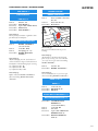
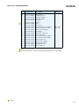
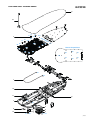
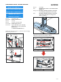
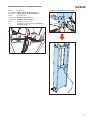
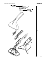
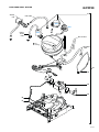
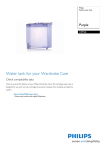
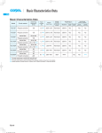
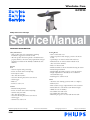
Wardrobe Care GC9920 Philips Consumer Lifestyle Service Manual PRODUCT INFORMATION Safety Information - This product meets the requirements regarding interference suppression on radio & TV. - After the product has been repaired, it should function properly and has to meet the safety requirements & legal regulations as laid down & officially established at this moment. Features Iron - Careeza soleplate with pointed tip - Power on switch cum iron ready lamp - Iron ready in 2 mins - Auto shut off in 5 mins - Suction & blowing button for active board - Steam trigger - Heel rest - Iron hose cord 1.6 m Steamer - Internal heating element - Power on switch cum steamer ready lamp - Steamer ready in 2 mins - Auto shut off in 5 mins - Suction & blowing button for active board - Steam trigger - Steamer hose cord 1.8 m Published by Philips Consumer Lifestyle 10/01 Printed in the Netherlands Ironing Board - Non-scorch board cover - Active & passive boards (Longer portion is the Active board) - Special shape on Active board for shirt & blouse - Refresh button on Active board for refresh mode (Auto shut off in 10 mins) - Heater on Active board - Bi-directional fan on Active board for blowing & suction - Board tilting mechanism - Board folding & locking strap for storage & transport - Height adjustment for board 0.75 m to 1.00 m in 22 intermediate steps - Rod hanger for steamer mode Stand - Automatic calc-cleaning system (2 mins to complete) - Boiler 4.5 bar - Heat resistant storage compartment for iron & steamer - Retractable auto cord-winder 3.5 m effective length - Wheels for ease of mobility - Detachable water tank 2.5 L - Detachable rinse tank 0.85 L - LED lamp for power-on, water tank & rinse tank © Copyright reserved Subject to modification GC9920 TECHNICAL INFORMATION - Power - Maximum Boiler Iron Steamer Board heater Fan : : : : : : Voltage : Frequency : Weight (product) : Weight (with package) : Product dimensions : in storage mode 2400 W at 240 V, 10 A 1200 W 800 W 500 W 400 W 40 W 230 V 50 - 60 Hz 20 kg 24 kg 500 x 480 x 760 mm (L x W x H) Indicator lamp All switch-cum-lamps on the appliance use blue LED. For the iron & steamer light, the LED flashes during heat up & burn steadily when ready. The power-on light on stand will remain lit as long as the appliance is plugged in & the main switch is on. Appliance power management scheme Please take note that the following combinations cannot be operated simultaneously: Iron mode + Steamer mode Iron mode + Refresh mode Start-up time Approximate 2 mins Approximate 5 mins if automatic calc-cleaning is required Board cover The non-scorch cover can withstand 230 deg C continuously for 45 mins. This allows iron to be rested horizontally on the cover during ironing. Board heating Heater is provided only in the active board. On the board cover, the feeling is warmth (< 60 deg C) & not scalding hot. For optimized performance of the appliance, the heater is permanently on during steamer & refresh mode while switches with iron during ironing mode. Active ironing board The ironing board has 2 portions: Passive & Active board. The longer portion is the Active board. The Active board is specially shaped for shirt or blouse during ironing, steamer & refresh mode. It also has a bi-directional fan & board heater that offers suction or blowing & board heating during use. For optimized performance of the appliance, fan is permanently on during use. Refresh mode During refresh mode, warm air blows out from the air vent at the side of the active board housing. The refresh mode runs for 10 mins & then switches off automatically. You can repeat the refreshing by pressing the refresh button again. Automatic calc-cleaning system When the power-on light blinks, automatic calc-cleaning is active. Wait 2 mins for the appliance to complete the calc-cleaning process. After calc-cleaning is completed, the rinse tray light blinks & a few beeps can be heard. Empty the rinse tray & re-insert it. The 0.85 L detachable rinse tank has sufficient capacity for 1 rinse (rinse volume 0.55 L) with buffer to avoid spillage while transporting to empty the contents. During automatic calc-cleaning, the appliance is disabled until the process is completed. 2-19 DISASSEMBLY ADVICE - IRONING BOARD FAN GRILLE 3 BOARD HEATER 1 FAN GASKET 4 BOARD TCO/FUSE 2 FAN ASSY 5 Remove Disassemble Disconnect Disassemble Disassemble GC9920 bolts A1 - A4 FAN GRILLE 3 4-pole cable of FAN ASSY 5 FAN ASSY 5 FAN GASKET 4 Remove heater terminal connections D1, D2 Unbend heater tabs E1 - E7 Disassemble Board heater Reassembly tip: Ensure fan assy orientation - light blue colour fan label to face board frame BOARD HOUSING ACTIVE 7 Remove BOARD STICKER 14 (on active board) Remove screws B1 - B20 Remove board plugs C1 - C3 Disassemble BOARD HOUSING ACTIVE 7 Reassembly tip: Adjust board plug C1, C2, C3 clockwise & counter-clockwise to align screw holes between board frame & board housing before screwing. C1: adjustment B1 - B6 C2: adjustment B7 - B12 C3: adjustment B13 - B14 Reassembly tip: Replace with new BOARD STICKER 14 after reassembling BOARD HOUSING ACTIVE 7 Disassembly tip: Do not over-bend heater tabs to prevent breakage Reassembly tip: The slot holes on the heater tab & board frame are for riveting. Use rivets SUS dia 3.2 x 6.35 & rivet gun when reassembling BOARD HEATER 1 Remove rivets F1, F2 Disassemble BOARD TCO/FUSE 2 Reassembly tip: Use rivets SUS dia 3.2 x 6.35 & rivet gun when reassembling BOARD TCO/FUSE 2 KNOB FLAP 10 KNOB 11 Remove screws G1, G2 Disassemble KNOB FLAP 10 Disassemble KNOB 11 COVER BUTTON REFRESH 12 BUTTON REFRESH ASSY 13 Disassemble COVER BUTTON REFRESH 12 (rotate anticlockwise) Remove screws H1, H2 Remove wire stud Disconnect 2-pole cable of BUTTON REFRESH ASSY 13 Disassemble BUTTON REFRESH ASSY 13 3-19 PARTS LIST - IRONING BOARD Pos Service code 1 2 3 4239 010 09690 4239 017 10080 4239 026 22820 4239 026 25910 4239 015 56230 4239 017 10090 4239 017 11040 4239 017 10100 4239 026 22750 4239 026 25870 4239 026 22830 4239 010 09750 4239 026 22840 4239 026 22760 4239 026 22780 4239 026 25880 4239 021 33280 4239 026 22810 4239 026 25900 4239 016 82220 4239 021 49080 4 5 6 7 8 9 10 11 12 13 14 55 57 GC9920 Description Board heater TCO/Fuse board Fan grille (Purple) Fan grille (Blue) Fan gasket Fan assy Fan * Board cover Board housing active (Purple) Board housing active (Blue) Button tilt (Dark grey) Rod hanger Knob flap (Dark grey) Flap (Dark grey) Cover button refresh (Purple) Cover button refresh (Blue) Button refresh assy Board sticker (Purple) Board sticker (Grey) Board heater rivet Hose holder assy Remark By order By order Note: Please order part with ‘*’ when servicing product which has date code wk934. = changed 4-19 EXPLODED VIEW - IRONING BOARD GC9920 6 57 C1 F2 F1 2 B12 B15 B11 C2 C3 B8 B14 B9 B7 B16 B17 B18 B19 B1 B20 B2 B10 B3 B13 Heater tab positions B4 B6 E5 B5 E6 E7 E4 E3 E2 E1 D1 D2 1 14 11 7 8 G2 G1 4 9 13 12 10 H1 H2 5 3 A1 - A4 5-19 DISASSEMBLY ADVICE - MOVING COLUMN MOVING COLUMN ASSY 15 PLATE PIVOT FLANGE LEFT 16 PLATE PIVOT FLANGE RIGHT 17 HANDLE LIFT LEFT 18 HANDLE LIFT RIGHT 19 Remove Disassemble Remove Remove Disassemble Disconnect GC9920 Remove Press screw M5 HANDLE LIFT LEFT 18 & HANDLE LIFT RIGHT 19 Pull upwards IRONING BOARD-MOVING COLUMN assy, detaching completely from the Stand. Place IRONING BOARD-MOVING COLUMN upside down, lying flat on ironing board surface as follows: screws M1 - M4 BACK COVER TOP 21 screw S1 screws T1, T2, T9, T10 PANEL LEFT ASSY 24 4-pole cable W4, 2-pole cable W5, Quick-connectors L3, N3 & Earth (Board heater) on STAND LECTRONICS 37 Undress the disconnected wires so that their ends are hanging freely from position Loc 1: Unhook 2x straps from the springs as follows: Strap 1 Strap 2 Spring 1 Spring 2 Loc 1 6-19 DISASSEMBLY ADVICE - MOVING COLUMN Remove Disassemble Disassemble Remove Disassemble Disassemble Remove Cut screws J1, J2 PLATE PIVOT FLANGE LEFT 16 PLATE PIVOT FLANGE RIGHT 17 screws K1, K2 HANDLE LIFT LEFT 18 HANDLE LIFT RIGHT 19 T10 Torx screws L1 - L8 3x cable ties to free the wires on MOVING COLUMN ASSY 15 GC9920 Disassemble MOVING COLUMN ASSY 15 7-19 EXPLODED VIEW & PARTS LIST - MOVING COLUMN GC9920 16 J1 15 18 L1 K1 L2 L4 L3 L5 L6 17 19 J2 L8 L7 K2 Pos Service code 15 4239 020 01350 4239 020 02511 4239 026 22920 4239 026 22930 4239 026 22940 4239 026 22950 16 17 18 19 = changed Description Remark Moving column assy By order Moving column assy * Plate pivot flange left (Dark grey) Plate pivot flange right (Dark grey) Handle lift left (Dark grey) Handle lift right (Dark grey) Note: Please order part with ‘*’ when servicing product which has date code wk934. 8-19 DISASSEMBLY ADVICE - STAND GC9920 WHEEL ASSY 31 CAP WHEEL PAINTED 32 FOOT ASSY 28 Remove screws R1 - R4 Disassemble FOOT ASSY E-RING 33 PANEL LEFT ASSY 24 Disassemble CAP WHEEL PAINTED 32 Disassemble E-RING 33 Disassemble WHEEL ASSY 31 SMPS 36 STAND ELECTRONICS 37 BACK COVER TOP 21 WIRE ASSY LED - STANDBY 39 BACK COVER BOTTOM 22 WIRE ASSY LED - WATER TANK 41 AUTO CORD WINDER 38 Remove Disassemble Remove Disassemble Remove Disconnect screws M1 - M4 BACK COVER TOP 21 screws N1 - N6 BACK COVER BOTTOM 22 screws P1, P2, P3 quick-connectors E, L, N at the back of AUTO CORD WINDER 38 Disassemble AUTO CORD WINDER 38 SPRING LIFT COLUMN ASSY 27 Remove IRONING BOARD-MOVING COLUMN assy (refer DISASSEMBLY ADVICEMOVING COLUMN) Remove screws Q1, Q2 Disassemble SPRING LIFT COLUMN ASSY 27 Remove Remove Disassemble Disconnect Remove Disassemble Disconnect Disassemble Remove Disconnect Disassemble Remove Disconnect Disassemble screw S1 screws T1, T2, T9, T10 PANEL LEFT ASSY 24 quick-connector W7 on STAND ELECTRONICS 37 LED cover WIRE ASSY LED - STANDBY 39 quick-connector W8 on STAND ELECTRONICS 37 WIRE ASSY LED - WATER TANK 41 screw U quick-connectors L4, N4 & 4-pole cable W3 on STAND ELECTRONICS 37 SMPS 36 screw V all connectors on STAND ELECTRONICS 37 STAND ELECTRONICS 37 9-19 WIRE LABELS ON STAND ELECTRONICS 37 Steamer Comm Black (W2) Iron Comm Black (W1) Steamer Live Brown (L2) Thermistor Blue and Orange (W11) GC9920 Standby LED Blue and Black (W7) Iron Live Brown (L1) Fan SMPS 24V/5V Cord winder 4x wire 4 x wire Neutral Red (W4) Black (W3) Blue (N5) Board HE-Fuse Brown (L3) SMPS Live Brown (L4) SMPS Neutral Blue (N4) Board HE-Fuse Blue (N3) Cord winder Live Brown (L5) A B D C E F Water tank LED Yellow and Black (W8) Rinse tank LED Red and Black (W6) Refresh Switch PCB (W5) G Rinse tank switch Black and Gray (W9) Reed Switch White (W10) Iron Neutral Blue (N1) Steamer Neutral Blue (N2) NOTE : ABC (brown, red, and blue) is a 3 pole connector to connect to boiler side. (W12) DEFG (white, blue, yellow and black) is a 4 pole conn to connect to boiler side (W13) 10-19 DISASSEMBLY ADVICE - STAND GC9920 PANEL RIGHT ASSY 25 PANEL FRONT BOTTOM 26 REED SWITCH ASSY 29 WIRE ASSY LED - RINSE TANK 40 IRON SLIDING TRAY ASSY 30 STEAMER ASSY 47 Remove Remove Disassemble Disconnect screw S2 screws T3, T4, T11, T12 PANEL RIGHT ASSY 25 quick-connector W10 on STAND ELECTRONICS 37 Disassemble REED SWITCH ASSY 29 Release catch at bottom of IRON SLIDING TRAY ASSY 30 Pull out completely IRON SLIDING TRAY ASSY 30 Remove T5, T6, T7, T8 Disassemble Boiler compartment Disconnect steam hose of HOSE CORD STEAMER 48 on EV1 Disconnect steamer Earth & quick-connectors L2, N2, W2 on STAND ELECTRONICS 37 Disassemble STEAMER ASSY 47 WIRE ASSY RINSE TANK SWITCH 42 CHASSIS BOILER ASSY 49 PUMP ASSY 50 ELECROVAVLE 51 Remove RINSE TANK ASSY 35 Disassemble PANEL FRONT BOTTOM Disassembly tip: Release 2x catches at the bottom of boiler chassis by inserting 2x screws (M4x8) into the holes located at Loc 2 & Loc 3 Refer following diagram. IRON ASSY 43 HOSE CORD IRON 46 Remove screw W Disassemble Backplate Disconnect quick-connectors of HOSE CORD IRON 46 at iron rear Disassemble IRON ASSY 43 SOLEPLATE ASSY 44 Lock 2 Lock 3 Disconnect Disconnect Disconnect IRON ELECTRONICS 45 Disassemble Remove Disassemble Remove Disassemble Remove Disassemble Disassemble Inlay screws X1 - X3 IRON ELECTRONICS 45 screws Y1 - Y3 Housing screws Z1 - Z3 Cover SOLEPLATE ASSY 44 Disconnect Remove Release Boiler chassis 3-pole cable W12 and 4-pole cable W13 boiler Earth, W6, W9, W11 steam hoses & connections on ELECTROVALVE 51 (EV1, EV2, EV3) De-air tube, Inlet tube, Safety cap Screws a1 & a2 2x catches at the Boiler chassis Release catch a2 Pull out chassis Pull out Disassemble Disassemble Disassemble Disassemble a1 Release catch Boiler chassis CHASSIS BOILER ASSY 49 WIRE ASSY LED - RINSE TANK 40 WIRE ASSY RINSE TANK SWITCH 42 PUMP ASSY 50 ELECTROVALVE 51 11-19 REPAIR INSTRUCTIONS GC9920 1. Due to the high wattage of the product, only the specified cordset must be used. 2. When replacing the ELECTROVALVE 51, please be reminded to apply loctite at the joints for good sealing. To check 5 V DC : 1) Probe at 5 V test point and N1/N2/N3. or 2) Probe at connector 9019 between VDD and GND 3. After the product is repaired, it should function properly & must meet the safety requirements & legal regulations as laid down & officially established at this moment. 2) 5 V DC 4. Basic checks for the STAND ELECTRONICS 37 as follows: N3 1) 5 V DC 4.1 Check for incoming AC voltage measured at L5 and N5 (220 - 240 V AC) N2 N1 L5 220 - 240 V AC N5 4.3 Check for AC power supply to Iron unit between L1 and N1 (220 - 240 V AC) 4.4 Check for AC power supply to Steamer unit between L2 and N2 (220 - 240 V AC) L2 L1 4.2 Check for output of 24 V DC and 5 V DC from switch mode power supply. To check 24 V DC : Probe at 24 V test point and N1/N2/N3. Iron 220 - 240 V AC 24V N3 24 V DC Steamer 220 - 240 V AC N2 N1 N2 N1 5.1 The calc clean process will automatically activate after 3.5 hrs of steaming. In terms of product usage time, it would depend on how often the consumer uses steam when he/she uses the product. 5.2 It is possible for service center to manually activate Auto Calc Clean process before time is due. The steps involved are as follows: - Unplug cordset from mains socket. - Allow boiler to cool down. (Boiler temperature must be < 50 Deg C for auto calc clean to take place) - Press & hold refresh button when plugging into the mains socket. - Release refresh button when power-on light starts blinking, indicating that calc clean process is active. 12-19 PARTS LIST - STAND, IRON ASSY, STEAMER & BOILER Pos Service code 20 21 22 23 24 4239 016 81880 4239 026 23090 4239 026 23100 4239 021 34230 4239 021 33550 4239 021 56331 4239 021 33560 4239 021 56341 4239 026 23080 4239 026 38951 4239 021 33840 4239 021 33470 4239 021 56301 4239 017 74040 4239 021 33530 4239 026 22850 4239 026 38931 4239 021 34220 4239 026 38941 4239 016 81890 4239 021 33570 4239 021 38420 4239 021 33600 4239 021 34370 25 26 27 28 29 30 31 32 33 34 35 36 37 38 4239 021 48980 4239 021 34350 4239 021 48030 4239 021 33520 4239 021 43310 4239 021 43320 4239 021 38380 4239 021 46950 GC9920 Description Pos Service code Boiler strap Back cover top (Grey) Back cover bottom (Dark grey) Steamer door hot foiled Panel left assy Panel left assy * Panel right assy Panel right assy * Panel front bottom (Grey) Panel front bottom * Spring lift column assy Foot assy Foot assy * Reed switch assy Iron sliding tray Wheel Wheel Frosted silver * Cap wheel painted Cap wheel * E-ring ID 10 Water tank assy (Purple) Water tank assy (Blue) Rinse tank assy 24 V SMPS (Switch Mode Power Supply) 24 V SMPS * Stand electronics Stand electronics * Auto cord winder (EU) Auto cord winder (EU) * Auto cord winder (Swiss) Auto cord winder (UK/SIN) Auto cord winder (Australia) 39 4239 017 74220 4239 017 75670 4239 017 74210 4239 017 11280 4239 017 74230 4239 017 11290 4239 017 74240 4239 020 01160 4239 020 02471 4239 020 01600 4239 020 02561 4239 020 02160 40 41 42 43 44 45 46 47 48 49 50 51 52 53 54 56 4239 021 41290 4239 021 33860 4239 021 47990 4239 021 34270 4239 021 48960 4239 021 47920 4239 020 01330 4239 020 02481 4239 020 01610 4239 020 02571 4239 021 34290 4239 021 48970 4239 020 01320 4239 020 02350 4239 017 09880 4239 017 09890 4239 026 22910 4239 015 58480 4239 015 56700 4239 015 58440 4239 026 23020 4239 026 22210 4239 026 26480 Description Wire assy LED - Standby Wire assy LED - Standby * Wire assy LED - Rinse tank Wire assy LED - Rinse tank * Wire assy LED - Water tank Wire assy LED - Water tank * Wire assy rinse tank switch Iron assy (Purple) Iron assy (Purple) * Iron assy (Blue) Iron assy (Blue) * Iron assy (Blue) (Hose holder version) Soleplate assy 230 V / 800 W Iron electronics Iron electronics * Hose cord iron Hose cord iron * Hose cord iron (Hose holder version) Steamer assy (Purple) Steamer assy (Purple) * Steamer assy (Blue) Steamer assy (Blue) * Hose cord steamer Hose cord steamer * Chassis boiler assy Chassis boiler assy * Pump service pack Electrovalve Foot pad Foot rubber (Black) * Wheel tread Wheel tread * Boiler compartment cover De-air valve De-air valve * Note: Please order part with ‘*’ when servicing product which has date code wk934. = changed 13-19 BLOCK DIAGRAM GC9920 RINSE E-VALVE STEAMER IRON STEAMER E-VALVE IRON CORD L,N,E,COMM 4x Conductor IRON E-VALVE PUMP STEAMER CORD L,N,E,COMM 4x Conductor 24 V DC, GND, DIR Sig, PWM Sig 4x Conductor BOILER 3x Conductor FAN STAND ELECTRONICS CONTROLLER L, N 2x Conductor MAINS PLUG L,N 2x Conductor BOARD HEATER 24 V DC, 5 V DC, 2x GND 4x Conductor SMPS Note: CONN means Signal wire 14-19 ELECTRICAL DIAGRAM GC9920 27 BOARD HEATER Refresh Sw ELECT FUSE T'MAL FUSE FAN L BD HEATER 4239 017 7411 24 FUSE1 BOILER HE LED-Rinse Tank Wire Assy 4239 017 7421 8 LED 3P F 3P M SOLDER 4PH 4239 017 7425 11 2PH 2PH 2PH 2PH 2PH 9017 9022 9016 9023 9018 F4.8 4239 017 7441 17 4239 017 7408 10 AWG26 23 4239 017 7415 AWG26 4239 017 7413 22 S-S E 4239 017 7417 24 220mm/Blue/AWG26 (XLPVC) Ribbon B19 R Sw-Rinse Tank Wire Assy 4239 017 7424 7 100mm/Blue/AGW26 COLUMN 9008 9013 4PH 2PH 9007 9020 9021 400mm 9001-R3 9004 (N) F4.8 9001-R2 9001-R1 9005 (L) F4.8 SOLDER RINSE TANK DETECT SW S-S Thermal Fuse FUSE2 F4.8 F 1600mm AWG26 (XLPVC) Ribbon S-S LED 4239 017 7416 20 LED-Water Tank Wire Assy 4239 017 7423 5 500mm/AWG26 (XLPVC) Ribbon 1800mm AWG24 (XLPVC) Ribbon 280mm/White/AGW26 Thermal Fuse R 1800mm AWG20 (TEFLON) Reed Sw Wire Assy 4239 017 7404 4 WATER TANK REED SW 2PT-M 2PT-F EARTH 1800mm AWG20 (TEFLON) SOLDER B19 F4.8 4239 017 7422 2 4PT-F 620mm/AWG26 (XLPVC) Ribbon 4x AWG26 F4.8 4PT-M FUSE2 R THERMAL FUSE STDBY LED FUSE1 28 4239 017 7428 F4.8 25 4239 017 7407 SMPS L 4239 017 7419 15 N E I EV2 - STEAMER F4.8 Cordwinder F4.8 16 4239 017 7418 9011 9025 9014 9010 F4.8 F4.8 F4.8 9015 F4.8 F4.8 L N N L SOLDER STEAMER IRON PLUG E 4239 021 3429 4239 021 3427 F4.8 Comm N 4239 017 7420 14 F4.8 F4.8 F4.8 L 13 4239 017 7409 F4.8 F4.8 E F4.8 9002 9009 EV3 - DRAIN E 9024 9012-R1 (EV1) 12 4239 017 7426 F4.8 N F4.8 PUMP L 9012-R2 (EV2) F4.8 H 9012-R3 (EV3) Comm 4P F 4P M N F4.8 F4.8 L F4.8 F4.8 G 24V 9006 (DC) GND GND 5V 4PH SOLDER STAND PCB 9012-R4 (PUMP) SOLDER E M tact B17 SPOT WELD Thermistor X2 SOLDER BOILER, SIDE VIEW R E E F4.8 J F4.8 HOSE L N HOSE EV1 - IRON E F4.8 M4.8 M4.8 F4.8 M4.8 F4.8 M4.8 F4.8 M4.8 F4.8 EARTH DAISY CHAIN 4239 017 7406 19 4239 017 7414 18 4239 017 7412 LEGEND 2PH 4PH SOLDER F4.8 B17 B19 4P M 4P F 3P M 3P F 4PT-M 4PT-F 2PT-M 2PT-F R M4.8 S-S 2P HEADER (JST XHP-2) 4P HEADER (JST XHP-2) Directly soldered to PCB Female faston connector 4.8 Stocko ID1.7 Pin receptable RBB8000R1.7-0.5 Stocko ID1.9 Pin receptable RBB 7854.001 R1.9 4-pole plug AMP 770275-1 (Male) 4-pole receptable AMP 770274-1 (Female) 3-pole plug AMP 770331-1 (Male) 3-pole receptable AMP 770333-1 (Female) JST XARR-01VF connector 2-pole SXH-002T-P0.6 terminal (Male) 2-pole SXH-002T-P0.6 terminal (Female) M4.3, Stocko RSB 7206 A4-1 Ring Terminal Male faston connector 0.8mm thickness Directly solder with heat shrink sleeve 15-19 EXPLODED VIEW - STAND GC9920 M1 21 M3 U 22 N1 36 N2 P1 24 37 P2 M2 N3 23 N4 P3 38 M4 N6 N5 V M5 LED cover Q1 S1 Q2 S2 T9 T10 T5 T6 39 T11 27 T1 T12 T2 30 T3 41 T4 T7 T8 54 25 35 29 28 R1 R2 R3 R4 34 52 33 53 31 26 32 16-19 EXPLODED VIEW - IRON ASSY GC9920 Inlay 45 X2 Backplate X3 X1 W Y2 Y3 43 Y1 Housing Z2 Z3 Cover Z1 44 46 17-19 EXPLODED VIEW - STEAMER GC9920 48 47 18-19 EXPLODED VIEW - BOILER GC9920 51 Safety cap Inlet tube EV2 EV1 Rinse outlet tube EV3 De-air tube Braided tube 49 20 50 56 40 42 19-19