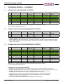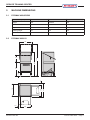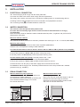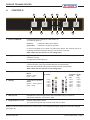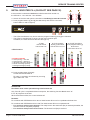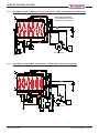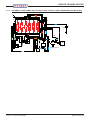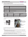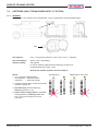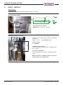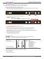
1
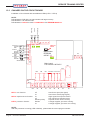
SERVICE TRAINING CENTER HOBART GmbH Service Manual EFFICIENT – RELIABLE – INNOVATIVE An ITW-Company ECOMAX 402/452/502 Start Serial No.: Facelift as of Serial No.: 8663 0001 – 8663 3999 8663 4000 EEPROM: 897547-6 EEPROM: 897547-17 ECOMAX 602/612/AM-10/AM-11 Start Serial No.: Facelift as of Serial No.: 8657 1001 – 8667 2999 8657 3000 EEPROM: 897547-6 EEPROM: 897547-17 This document is produced for internal use only. The detailed settings and servicing must be carried out by service technicians qualified by HOBART. Reproduction of this document is prohibited without the written permission of Hobart GmbH. SM-21912-001-GB © HOBART GmbH, Service Training Center Issue: 18.03.2011 SERVICE TRAINING CENTER Contents 1. Standard Models – Overview ...................................................................................................................................... 3 1.1Ecomax 402 Glasswasher (G-Series) .............................................................................................................. 3 1.2 Ecomax 452 FRONTDOOR-dishwasher (F-Series) ......................................................................................... 3 1.3 Ecomax 502 Frontdoor-dishwasher (F-Series) .......................................................................................... 3 1.4 Ecomax 602/612 Hood-dishwasher ................................................................................................................... 4 2. Machine Dimensions ......................................................................................................................................................... 5 2.1Ecomax 402/502 ......................................................................................................................................................... 5 2.2 ecomax 602/612 ......................................................................................................................................................... 5 3.Installation ........................................................................................................................................................................ 6 3.1Electrical Connection ....................................................................................................................................... 6 3.2Water Connection ................................................................................................................................................. 6 3.3 Drain Connection .................................................................................................................................................. 6 4.Controls .............................................................................................................................................................................. 7 5. Initial Booster fill (Facelift see page 32) ............................................................................................................. 8 6.Hydraulic Schematics .................................................................................................................................................... 9 6.1Legend of Components for ecomax 402/502/452 have look to page 3 ............................................... 9 6.1.1 Schematic for ecomax 402-10/502-10/502-30/502-141 (with pressure booster) ............................... 10 6.1.2 Schematic for ecomax 402-12/452-90 /502-12 (with pressure booster) ............................................. 10 6.1.3 Schematic for ecomax 402-20/452-91/502-20/502-21 (with pressure-less booster) ....................... 11 6.1.4 Schematic for ecomax 402s-10/502s-10 (with pressure-less booster) ........................................... 11 6.1.5 Schematic for ecomax 402S-12/402S-20/502S-12/502S-20 (with pressure-less booster) ............. 12 6.2Legend of Components for ecomax 602/612/AM-10/AM-11 ....................................................................... 13 6.2.1 Schematic for ecomax 602-10/602-141/aM-10/AM-11 with Pressure Booster ................................... 14 6.2.2 Schematic for ECOMAX 602-11/612-10/612-40/612-41 with Pressure-less Booster .......................... 14 6.2.3. Schematic for ECOMAX 602S-11/612S-10 with Pressure-less Booster ............................................. 15 7.Filling .................................................................................................................................................................................. 16 7.1Waterbreak with flowmeter ......................................................................................................................... 16 7.1.2.double-ball backflow preventer ............................................................................................................... 16 7.2 Pressure Transmitter B3/B4 ........................................................................................................................... 17 7.3 Dosing equipment ............................................................................................................................................... 18 7.4 Softener (only for machines with "S" option) ........................................................................................ 19 7.4.1 General ................................................................................................................................................................... 19 7.4.2 Softener Check Procedure ........................................................................................................................... 20 7.5 Booster / Tank / Temperature Probes ......................................................................................................... 21 8.Washing ............................................................................................................................................................................... 22 8.1 Technical Data – Wash Pump/Rinse Pump .................................................................................................... 22 9.Hood – Details .................................................................................................................................................................. 23 10. Electronic Control ...................................................................................................................................................... 24 10.1 10.2 10.3 10.4 10.5 Customer Settings ............................................................................................................................................. 24 Service Diagnostics (Facelift see page 32) ............................................................................................... 25 Machine Type Setting (Facelift see page 32) ............................................................................................. 28 Softener Test Program (Only Machines with "S" Option) ................................................................... 29 Printed Circuit board (Facelift see page 33) ........................................................................................... 30 11.Dosage Times .................................................................................................................................................................... 31 12Facelift february 2011 ................................................................................................................................................. 32 12.1 New Equipment and Program functions .................................................................................................... 32 12.2temperature modification ............................................................................................................................... 33 12.3 Changes on the Circuit board ....................................................................................................................... 33 Page 2 / Ecomax & AM Series SM-21912-001-GB SERVICE TRAINING CENTER 1. Standard Models – Overview 1.1 Ecomax 402 Glasswasher (G-Series) No. Device Code EEPROM1) Program No. (LED) Programs Racks/Hr. Glasses/Hr. Wiring Diagram 1 Ecomax 402-10 897547-006 9 (H28) 2 (90 s / 120 s) 40 / 600 01-295680-004 2 Ecomax 402-12 897547-006 9 (H28) 2 (90 s / 120 s) 40 / 600 01-295680-004 3 Ecomax 402S-10 897547-006 11 (H19) 2 (90 s / 120 s) 40 / 600 01-295681-204 4 Ecomax 402S-12 897547-006 11 (H19) 2 (90 s / 120 s) 40 / 600 01-295681-204 5 Ecomax 402-20 897547-006 10 (H29) 2 (90 s / 120 s) 40 / 600 01-295682-004 6 Ecomax 402S-20 897547-006 11 (H19) 2 (90 s / 120 s) 40 / 600 01-295682-004 Note: The green-marked rows refer to products targeted for the German market. 1) As of facelift: EEPROM 897547-17. 1.2 Ecomax 452 FRONTDOOR-dishwasher (F-Series) No. Device Code EEPROM Program No. (LED) Programs Racks/Hr. Glasses/Hr. Wiring Diagram 1 Ecomax 452-90 897547-017 6 (H25) 2 (60s / 180s) 60 / 1080 01-296685-002 2 Ecomax 452-91 897547-017 7 (H26) 2 (60s / 180s) 60 / 1080 01-295687-004 –– Ecomax 452-90: pressure booster without waterbreak/without rinse pump, –– Ecomax 452-91:pressure-less booster with backflow preventer instead of waterbreak/with rinse pump, –– Both versions have built-in rinse aid, detergent, and drain pump 230/50/1 (15A) with plug and rollerballcaster at the rearside. 1.3 Ecomax 502 Frontdoor-dishwasher (F-Series) No. Device Code EEPROM1) Program No. (LED) Programs Racks/Hr. Teller/Hr. Wiring Diagram 1 Ecomax 502-10 897547-006 6 (H25) 2 (60 s / 180 s) 60 / 1080 01-295685-002 2 Ecomax 502-12 897547-006 6 (H25) 2 (60 s / 180 s) 60 / 1080 01-295685-002 3 Ecomax 502S-10 897547-006 8 (H27) 2 (60 s / 180 s) 60 / 1080 01-295686-202 4 Ecomax 502S-12 897547-006 8 (H27) 2 (60 s / 180 s) 60 / 1080 01-295686-202 5 Ecomax 502-20 897547-006 7 (H26) 2 (60 s / 180 s) 60 / 1080 01-295687-004 6 Ecomax 502S-20 897547-006 8 (H27) 2 (60 s / 180 s) 60 / 1080 01-295687-004 7 Ecomax 502-21 897547-006 7 (H26) 2 (60 s / 180 s) 60 / 1080 01-295687-002 6 Ecomax 502-30 897547-006 6 (H25) 2 (60 s / 180 s) 60 / 1080 01-295685-004 6 Ecomax 502-141 897547-006 6 (H25) 2 (60 s / 180 s) 60 / 1080 01-295685-002 Note: The green-marked rows refer to products targeted for the German market. 1) As of facelift: EEPROM 897547-17. Remarks for device code Ecomax 402/502: –– Ecomax -10/-12 (without "S") have pressure booster without waterbreak/without rinse pump –– Ecomax -12 generally always have a built-in waterbreak/rinse pump, detergent pump and drain pump –– Ecomax -20 have pressure-less booster with waterbreak/with rinse pump (UK-version) –– Ecomax -21 have pressure-less booster with waterbreak/with rinse pump –– Ecomax -30 have pressure booster without waterbreak/without rinse pump 230/50/1/25A –– Ecomax -141 have pressure booster without waterbreak/without rinse pump 230/50/3 –– S means that a softener is integrated. Generally, all "S" machines have a built-in waterbreak and rinse pump. SM-21912-001-GBEcomax & AM Series / Page 3 SERVICE TRAINING CENTER 1.4 Ecomax 602/612 Hood-dishwasher No. Device Code EEPROM1) Program No. (LED) Programs Racks/Hr. Wiring Diagram 1 Ecomax 602 -10 / 897547-006 1 (H20) 2 (75 s / 150 s) 48 01-294570-002 2 AM-10 / AM-11 897547-006 1 (H20) 2 (75 s / 150 s) 48 01-294560-002 3 Ecomax 602 -11 897547-006 2 (H21) 2 (75 s / 150 s) 48 01-294575-002 4 Ecomax 602S -11 897547-006 3 (H22) 2 (75 s / 150 s) 48 01-294575-002 5 Ecomax 612 -10 897547-006 4 (H23) 2 (60 s / 120 s) 60 01-294580-002 6 Ecomax 612S -10 897547-006 5 (H24) 2 (60 s / 120 s) 60 01-294580-002 7 Ecomax 612 -40 897547-006 4 (H24) 2 (60 s / 120 s) 60 01-294580-826 8 Ecomax 612 -41 897547-006 4 (H24) 2 (60 s / 120 s) 60 01-294580-826 9 Ecomax 612 -141 897547-006 1 (H24) 2 (60 s / 120 s) 60 01-294570-003 Note: The green-marked rows refer to products targeted for the German market. 1) As of facelift: EEPROM 897547-17. Remarks for device code Ecomax 602/612/AM10/AM-11: –– Ecomax 602-10/AM-10/AM-11 have pressure booster without waterbreak/without rinse pump,without detergent dosage pump, without drain pump. –– Ecomax 602-11/all 612 generally always have waterbreak/rinse pump –– Ecomax 612-40 with rinse pump and 11 kW booster 220V/50/3/PE. –– S means that a softener is integrated. Generally, all "S" machines have a built-in waterbreak and rinse pump. Page 4 / Ecomax & AM Series SM-21912-001-GB SERVICE TRAINING CENTER 2. Machine Dimensions 2.1 Ecomax 402/452/502 Dimensions (mm) Ecomax 402 Ecomax 452 Ecomax 502 Height 700 830-852 830 Width 435 550 575 Depth 530 600 600 Loading height 301 356 356 Rack size 385x385 / 396x396 450x450 / 500x500 500x500 2.2ecomax 602/612 107 821 635 740 107 200* 860* 1480* 1960* 440 713 635 SM-21912-001-GBEcomax & AM Series / Page 5 SERVICE TRAINING CENTER 3.Installation 3.1 Electrical Connection The electrical supply shall comply with the name-plate data. Line fuses and cable cross section shall comply with the requirements The supply cord must be connected via a cut-off device (isolating switch or accessible plug device). According to EN 60 335 the appliance must be connected to an equipotential conductor. The connecting screw ( ) is located beside the cable inlet. 3.2Water Connection The machines must be operated with potable water. For water with an extremely high mineral content an external demineralization is strongly recommended. Ideal conductivity value for washware made of stainless steel 80 μS/cm, for glasses 100 µS/cm and for dishes 200 to 400 μS/cm Machines without softener: The machine should be connected to soft and if possible warm water (up to 3 °dh = 0.5 mmol/l, max. 60°C). Machines with softener: The machine should be connected to warm water if possible (max. 60°C). Softener has to be adjusted according to water hardness. Line Flow Ecomax 402-10 / 402-12 / 502-10 / 502-12 / 602-10 / AM-10 / AM-11 (without rinse pump M2): Line flow pressure 2 – 6 bar. If the line flow pressure is below 2 bar, provide a rinse pump at site. If line flow pressure is above 6 bar, provide a pressure reducing valve. All other models (with rinse pump): Line flow pressure 0.8 – 6 bar. Important: The line flow pressure must not be less than 0.8 bar. If the line flow pressure is above 6 bar, provide pressure reducer at source. Connect the union nut "A" (3/4") of the water supply hose to the site shut off valve. Do not kink or cut the supply hose. Eventually needed extension has to be provided with a suitable pressure hose (e.g. 324088-1). max. 650 mm Machine with drain pump (optional) Connection between machine and site drain must not e xceed max. height of 650 mm. Do not place the drain hose loosely on the floor (the hose could be rubbed through). Fix it at site! Do not kink drain hose. Page 6 / Ecomax & AM Series Machine without drain pump Ensure gravity drain. Drain hose must not exceed the height of 100 mm between floor and lower edge of the hose. Otherwise it could be that water remains in tank and hose. Do not kink drain hose. max. 100 mm 3.3Drain Connection SM-21912-001-GB SERVICE TRAINING CENTER 4.Controls 2 H1 1 Machine ON/STOP 2 H2 4 5 6 7 3 H3 1 H4 Pushing this button switches the dishwasher on. The LED H4 lights up. flashing permanent = Machine is filling and heating. = Machine is ready for operation. In case of operating error or faults, by pushing this button, the machine can be immediately switched-off without having to run the drain cycle first. After switch off, the machine is not voltage free! 2 Program buttons By pushing these buttons, it is possible to select between short cycle (1) and standard cycle (2). The appropriate LED lights up. 3 Drain/OFF button By pushing and holding (3 seconds) this button, the self-cleaning cycle starts. At the end of the cycle, the machine switches off automatically. Machines with optional drain pump will drain the tank automatically. After switch off, the machine is not voltage free! 4 Display Temperature indication Tank Temp. B2 Wash all models green: > 55°C (H14 - H19) Booster Temp. B1 5 Display Temperature indication Rinse green: > 75°C (>63°C) (H24 - H29) >75°C >70°C >65°C >55°C >45°C >35°C --------- 6 Salt required Indicates the need for regeneration salt to be added (only for machines with built-in softener). H10 and H11 flash. 7 Regeneration indicator Softener regeneration active. The cycle running time may increase. H10 and H11 flash. >55°C >50°C >45°C >40°C >35°C >30°C --------- all models model except -402 -402 only >63°C >60°C >55°C >50°C >45°C >35°C --------- Note: For serial numbers starting as of February 2011, the temperature display categories have been changed (see page 32). SM-21912-001-GBEcomax & AM Series / Page 7 SERVICE TRAINING CENTER 5. Initial Booster fill (Facelift see page 32) If the machine is switched on before the initial booster fill is carried out, the LEDs H14 - H17 and H24 - H27 will flash. ☞☞ Switch off machine and open the hood/door. Overflow pipe must be inserted. H27 H26 H25 H24 H17 H16 H15 H14 ☞☞ Push program buttons [1] and [2] simultaneously and hold for 3 seconds; button LEDs H1 and H2 light up. –– The LEDs H20-H29 are only shown after the program buttons [1] and [2] are released. –– The LEDs H1 and H2 light up as long as the menu remains open. In addition, the LEDs H10 and H20-H22 also light up. 1. Start LED H10 and H20 to H22 "on" 2. Push program button [1] two times. LED H10 to H12 "on" LED allocation: 3. Close hood/door. Push program button [1] three times. LED H10 to H15 "on" 6. Initial booster fill 5. Hose priming – rinse aid 4. Hose priming – detergent 3. Adjustment of water hardness 2. Rinse aid dosage quantity 1. Detergent dosage quantity 4. Push program button [2] briefly to start the initial booster fill. Fill valve Y1 activation is indicated by a moving light: LEDs H24 - H27. ATTENTION: Hood/door must not be opened during initial booster fill! Only if the fill cycle is completed without interruption, the switching function S03 is set to "0". If not, all programs are locked. When the booster is filled, the control switches off. Remarks: For machines with EEPROM revision <L1.0: Initial booster fill occurs for a predetermined set time. For machines with EEPROM revision L1.0: The initial booster fill is not completed until: –– For machines with pressure booster: The ready level in the wash tank (B4) is reached (thereafter, the machine must be completely emptied). –– For machines with pressure-less booster: The booster level (B3) is reached. Page 8 / Ecomax & AM Series SM-21912-001-GB SERVICE TRAINING CENTER 6.Hydraulic Schematics 6.1Legend of Components for ecomax 402/502 (Ecomax 452: see page 3) Ecomax 402 -10 402S -12 -10 -12 402 402S -20 -20 502 -10 502S -12 -10 -12 502 502S -20 -20 B1 Temperature sensor booster X X X X X X X X X X X X B2 Temperature sensor tank X X X X X X X X X X X X B3 Pressure transmitter booster --- --- X X X X --- --- X X X X B4 Pressure transmitter tank X X X X X X X X X X X X E1 Booster heating 5.50 kW 400/3/N/PE 3x13A/3x16A --- --- --- --- --- --- A A A A --- --- E1 Booster heating 230/1/N/PE 1x25A 3.70 kW --- --- --- --- --- --- --- --- --- --- A A E1 Booster heating 230/1/N/PE 1x20A 3.70 kW --- --- --- --- X X --- --- --- --- --- --- E1 Booster heating 1.80 kW 230/1/N/PE 1x13A/1x16A A A A A A A --- --- --- --- X X E2 Tank heating X X X X X X X X X X X X X X X X X X --- --- --- --- --- --- --- --- --- --- --- --- X X X X X X --- --- X X X X --- --- X X X X X X X X X X X X X X X X 1.80 kW M1 Wash pump C1 5.0 µF 0.25 kW M1 Wash pump C1 10.0 µF 0.37 kW M2 Rinse pump C2 4.0 µF 0.14 kW, 0.6A M3 Rinse aid dispenser M4 Detergent dispenser Kit X Kit X X X Kit X Kit X X X M5 Drain pump Kit X Kit X X X Kit X Kit X X X S1 X X X X X X X X X X X X Reed-switch – hood/door S2 Impeller --- --- X X --- X --- --- X X --- X S3 Salt deficiency switch --- --- X X --- X --- --- X X --- X Y1 Solenoid valve – fill 5 l/min. --- --- X X X X --- --- X X X X Y1 Solenoid valve – fill 15 l/min. X X --- --- --- --- X X --- --- --- --- Y3.1 Valve resin --- --- X X --- X --- --- X X --- X Y4.2 Switching valve softener --- --- X X --- X --- --- X X --- X 1 Water supply hose X X X X X X X X X X X X 2 Waterbreak (previously airgap) --- --- X X X X --- --- X X X X Backflow preventer X X --- --- --- --- X X --- --- --- --- 3 Pressure-less booster --- --- X X X X --- --- X X X X Pressure booster X X --- --- --- --- X X --- --- --- --- 4 Wash arms X X X X X X X X X X X X 5 Rinse arms X X X X X X X X X X X X 6 Salt chamber --- --- X X --- X --- --- X X --- X 7 Resin --- --- X X --- X --- --- X X --- X Notes: A = Delivery status connected load (according to wiring diagram) –– part number installation kit for drain pump Ecomax 402: 01-240784-1 –– part number installation kit for drain pump Ecomax 402S: 01-510154-1 –– part number installation kit for drain pump Ecomax 502: 01-240785-1 –– part number installation kit for drain pump Ecomax 502S: 01-510153-1 –– part number installation kit for detergent dispenser Ecomax 402/502:01-240786-1 –– Ecomax 502-20 and 502-21 are rotating current variants. –– Ecomax 502-30 (230/50/1/25A) and 502-141 (230/50/3) are pressure booster variants. SM-21912-001-GBEcomax & AM Series / Page 9 SERVICE TRAINING CENTER 6.1.1 Schematic for ecomax 402-10/502-10/502-30/502-141 (with pressure booster) 4 5 S1 2a Y1 15 l/min 5 4 1 B4 3a B1 B2 1E2 E1 M1 M3 Booster draining Drain 6.1.2 Schematic for ecomax 402-12/452-90/502-12 (with pressure booster) 4 5 S1 2a Y1 15 l/min 5 4 1 M4 3a B1 B4 B2 1E2 M1 M5 E1 M3 Booster draining Drain Page 10 / Ecomax & AM Series SM-21912-001-GB SERVICE TRAINING CENTER 6.1.3 Schematic for ecomax 402-20/452-91/502-20/502-21 (with pressure-less booster) Note: Ecomax 452-91 has a backflow preventer instead of a waterbreak. 4 5 S1 2 5 l/min Y1 5 4 1 M3 M4 B4 B2 3 B1 E2 B3 E1 M1 M5 M2 Booster draining Drain 6.1.4 Schematic for ecomax 402s-10/502s-10 (with pressure-less booster) 4 5 S1 S2 2 5 l/min Y1 5 4 1 M3 B4 B2 1E2 6 M1 S3 3 B1 Y4.2 B3 E1 7 M2 Booster draining Drain Y3.1 SM-21912-001-GBEcomax & AM Series / Page 11 SERVICE TRAINING CENTER 6.1.5 Schematic for ecomax 402S-12/402S-20/502S-12/502S-20 (with pressure-less booster) 4 5 S1 S2 2 5 l/min Y1 5 4 1 M3 B4 B2 1E2 M4 6 M1 S3 3 B1 Y4.2 E1 7 M5 Drain Page 12 / Ecomax & AM Series B3 M2 Booster draining Y3.1 SM-21912-001-GB SERVICE TRAINING CENTER 6.2Legend of Components for ecomax 602/612/AM-10/AM-11 Ecomax 602-10 602-141 Ecomax 602-11 Ecomax 602S-11 Ecomax 612-10 Ecomax 612S-10 AM-10 AM-11 B1 Temperature sensor booster X X X X X X X B2 Temperature sensor tank X X X X X X X B3 Pressure transmitter booster --- X X X X --- --- B4 Pressure transmitter tank X X X X X X X E1 Booster heating 5.50 kW A --- --- --- --- A A E1 Booster heating 6.10 kW --- A A A A --- --- Booster heating 4.10 kW Multiphasing 230/50/1 25A --- X X X X --- --- E2 Tank heating X X X X X X X M1 Wash pump 0.40 kW/12.5 µF X X X --- --- X X Wash pump 0.73 kW/16 µF --- --- --- X X --- --- --- X X X X --- --- 2.50 kW M2 Rinse pump M3 Rinse aid dispenser X X X X X X X M4 Detergent dispenser (retrofit kit) X X X X (retrofit kit) X M5 Drain pump (retrofit kit) (retrofit kit) X X X (retrofit kit) (retrofit kit) S1 Reed-switch – hood S2 X X X X X X X Impeller --- --- X --- X --- --- S3 Salt deficiency switch --- --- X --- X --- --- Y1 Solenoid valve – fill 5 l/min. --- X X X X --- --- Y1 Solenoid valve – fill 15 l/min. X --- --- --- --- X X Y3.1 Valve resin --- --- X --- X --- --- Y4.2 Switching valve softener --- --- X --- X --- --- X X X X X X X --- X X X X --- --- X --- --- --- --- X X --- X X X X --- --- Pressure booster X --- --- --- --- X X 4 Wash arms X X X X X X X 5 Rinse arms X X X X X X X 6 Salt chamber --- --- X --- X --- --- 7 Resin --- --- X --- X --- --- 1 Water supply hose 2 Waterbreak (previously airgap) 2a Backflow preventer 3 Pressure-less booster Notes: –– A = Delivery status connected load (according to wiring diagram) –– Ecomax 612-40 is a machine with rinse pump and 11 kW booster (220/60/30). –– Ecomax 612-41 is a machine with pressure pump and 11 kW booster (380/60/3). –– part number installation kit for drain pump Ecomax 602/AM-10-11 with installation manual: 01-240784-1 –– part number installation kit for detergent dispenser Ecomax 602/AM-10-11 with installation manual: 01-246480-1 SM-21912-001-GBEcomax & AM Series / Page 13 SERVICE TRAINING CENTER 6.2.1 Schematic for ecomax 602-10/602-141/aM-10/AM-11 with Pressure Booster S1 4 2a 5 15 l/min 5 Y1 1 4 M4 only AM-11 M4 B4 B2 1E2 M1 3a B1 E1 Drain M3 Booster draining 6.2.2 Schematic for ECOMAX 602-11/612-10/612-40/612-41 with Pressure-less Booster S1 4 2 S2 5 5 l/min Y1 1 M4 B4 B2 B3 1E2 M3 M1 3 B1 1E1 M2 M5 DRAIN Page 14 / Ecomax & AM Series booster draining SM-21912-001-GB SERVICE TRAINING CENTER 6.2.3. Schematic for ECOMAX 602S-11/612S-10 with Pressure-less Booster S1 2 S2 4 5 5 l/min Y1 1 M4 B4 B2 1E2 B3 Y4.2 M3 6 M1 7 S3 3 B1 1E1 M2 Y3.1 M5 Drain Booster draining SM-21912-001-GBEcomax & AM Series / Page 15 SERVICE TRAINING CENTER 7.Filling 7.1Waterbreak with flowmeter The flowmeter is activated by the impeller magnet. The impeller monitors the incoming water flow by counting impulses. The count rate is 200 impulses per liter. Maintenance Check whether water leaking from the airgap overflow (see figure) enters the wash tank chamber (visual inspection). If so, the leaking water quantity must not exceed 100 ml per fill step. All Ecomax machines with "S" Flowmeter Ecomax 402-20 / 502-20 / 602-11 / 612-10 / 612-40 / 612-41 Water flow Connection for filling supply Water flow Connection for filling supply Overflow Overflow Water for regeneration Fresh water to booster or softener Blind plug Fresh water to booster or softener 7.1.2. double-ball backflow preventer Ecomax machines with pressure booster (402-10/-12 / 452-90 / 502-10/-12 / 602-10 / AM-10 / AM-11) have a built-in backflow preventer. Ecomax 452-91 also has a backflow preventer (pressure-less booster). Overflow Water flow connection for filling supply Y1 Page 16 / Ecomax & AM Series Fresh water to booster SM-21912-001-GB SERVICE TRAINING CENTER 7.2Pressure Transmitter B3/B4 Via air traps (booster/wash tank) compressed air will be directed via clear hoses to the pressure transmitter booster (B3) and wash tank (B4). The transmitter changes the upcoming pressure into DC voltage which will be processed by the control as a water level message. Below example: 602S-11 Output Voltage Pressure Transmitter B3 Booster (if installed) approx. 0.50 V ± 60 mV Booster is empty. Fill valve will be activated approx. 0.60 V Booster heating will be switched on (heating up to fill start temperature 85 °C). approx. 0.90 V Booster is filled. Fill valve closes. Output Voltage * Pressure Transmitter B4 Tank approx. 0.50 V ± 60 mV Wash tank is empty. approx. 0.65 V Tank heating will be switched on. approx. 0.90 V Machine is ready for operation (tank is filled). * Additions for pressure transmitter B4 (tank): Ecomax Tank Heating ON Tank Filled Tank Heating ON While Washing 402 0.60 V 0.65 V 0.58 V 452/502 0.60 V 0.75 V 0.58 V 602/612 0.65 V (approx. 13 l) 0.90 V (approx. 21 l) 0.60 V NOTE: –– The hoses must incline above tank level and/or booster level to enable the condensate to drain off. –– The voltage value "tank full" is approx. 0.1 V to 0.15 V higher after rinse. PCB Detail Transmitter Arrangement + 0V 5 Press. Transmitter B3 Booster Voltage Signal from Transmitter 6 0 +5 V 7 + +5 V B3 Pressure transmitter Booster (not for Ecomax 402-10/-12, 502-10/-12, 602-10, or AM-10/-11) X14 Temp. Probe B2 Tank 1 Temp. Probe B1 Booster 0V 8 Press. Transmitter B4 Tank Voltage Signal from Transmitter 10 9 0 B4 Pressure transmitter Tank (all models) As a preventive measure, the pressure transmitters are covered with a protective foil 01-297533-1, (since April 28, 2009; starting with serial number 8657 1160). NOTE: –– The voltage supply of the two pressure transmitters is approx. 5 V. This voltage is measured between X14 Pin 5 (+5 V) and X14 Pin 6 (0 V) pressure transmitter booster B3, respectively, X14 Pin 8 (+5 V) and X14 Pin 9 (0 V) pressure transmitter tank B4. –– The output voltage is measured between X14 Pin 7 (+) and X14 Pin 6 (0 V) pressure transmitter booster B3, respectively, X14 Pin 10 (+) and X14 Pin 9 (0 V) pressure transmitter tank B4. If the sensor B3, B4 is outside the "normal" range (> 4.0 V / < 0.3 V), then the control is switched off. Service, customer, or machine selection menu can be still opened. The transmitter can be checked in the service menu (see section 10.2 Service Diagnostics on page 25). SM-21912-001-GBEcomax & AM Series / Page 17 SERVICE TRAINING CENTER 7.3Dosing equipment Dispensers Detergent Rinse aid Ecomax Part No. Delivery Rate Hose Inside 602/612 883828-2 3.0 l/hr Kit 775608-2 402/452/502 775556-2 602/612 883828-1 0.4 l/hr Kit 775608-1 402/452/502 775556-1 Pre-Adjusted Values Detergent see section 11. Dosage Times on page 31 Rinse aid Dosage Detergent Pre-dosing is activated simultaneous with fill valve Y1 or rinse pump M2. Wash dosing is activated simultaneous with the wash M1 pump. Rinse aid Pre-dosing is activated after the end of the fill cycle. Wash dosing is activated after the end of wash cycle. Hose priming and factory settings see section 10.1 Customer Settings on page 24. Maintenance 1. Check hoses, dispensers and connections. 2. As a precaution, the dosing hoses have to be replaced every two years (hoses inside dispensers, suction and pressure hoses). Dosing hoses (sold by meter) – part no. 01-246301-099 Page 18 / Ecomax & AM Series SM-21912-001-GB SERVICE TRAINING CENTER 7.4 Softener (only for machines with "S" option) 7.4.1General Before first run, the softener has to be filled with 1.5 kg of regeneration salt and potable water. Y3.1 Salt capacity: max. 1.5 kg (coarse grained, 3-8 mm, max.10 mm – no tablets) Salt consumption: approx. 40 g / regeneration Softener setting: see page 20 In case of softener replacement the fastening nut has to be re-tightend after three wash cycles. Special tool needed (softener wrench 775920-1) NOTE: 1. Y4.2 (switching drain/booster) de-energized = switched to drain energized = filling into booster. Salt deficiency Regeneration in process 2. It will take several wash cycles until the salt indicator switches off. 3. Salt deficiency will be indicated by flashing LEDs H10 + H11. 4. Active softener regeneration is indicated during operation by flashing LEDs H20 + H21. The cycle running time may be prolonged. SM-21912-001-GBEcomax & AM Series / Page 19 SERVICE TRAINING CENTER 7.4.2 Softener Check Procedure What you need to verify the softener function: 1. Test kit to measure the water hardness (part number 607236). Pay attention to expiry-date. 2. A temperature compensated conductivity-meter 609909 (possibly pH indicator strips 609927). How, respectively, where to measure? Use clean tea-cup or beaker for sampling water. 1. Take measurement of the total water hardness (°dh) at the tap where the machine is connected to. 2. Measure the conductivity (μS/cm) at the tap where the machine is connected to. 3. Measure the hardness of the water in the booster. Therefore, the booster drain hose is to be used. Discard the first cup of water to ensure that no residuals from the hose falsifies the measured value. 4. Measure the conductivity of the booster water. Adjustment of softener setting according to the hardness of incoming water: 1. Ensure adequate softener setting: H01 = up to 7°dh 20 wash cycles (see section 10.1 Customer Settings on page 24) H02 = 8 to 14°dh 15 wash cycles H03 = 15 to 21°dh 10 wash cycles H04 = 22 to 30°dh 5 wash cycles 2. Ensure that the salt chamber contains salt. 3. Ensure that granular salt is used (salt tablets are not allowed). 4. Ensure that the salt chamber has been filled up with water. Approximate values if softener function is O.K.: The conductivity of the booster water shall be about 300μS/cm higher than the conductivity of that water taken at the tap. For example: If the total hardness of the incoming water is 500μS/cm, the conductivity of the booster water will be roughly 800μS/cm. If this value is significantly higher (e.g. 3000 μS/cm), an incorrect softener function is very likely. Further steps: 1. Adjust the softener to "H04" to ensure a new regeneration will be actuated every 5 cycles. 2. Select the shortest program and take a sample of water (a tea-cup) at the booster drain hose immediately after the program cycle has ceased. 3. Measure and note down the water hardness. 4. Measure and note down the conductivity. Never run the softener test program at the beginning of the herein described procedure because it is unavoidable that salt will be flushed into the system. Thus, measurements would become incorrect. Proceed as follows in case of too high hardness and/or conductivity values: 1. Remove the right side panel. 2. Activate the softener test program as described on page 29. If the sequential operation deviates from the described one, it is very likely that the softener valve Y4.2 is jammed. The booster must be flushed thoroughly at the end of this procedure (run 5 wash cycles) to ensure that the chloride content is at an acceptable level to prevent corrosion. Page 20 / Ecomax & AM Series SM-21912-001-GB SERVICE TRAINING CENTER 7.5 Booster / Tank / Temperature Probes Parts with Booster Part Numbers Ecomax 402 Ecomax 452/502 Ecomax 602/612 Booster heating E1 01-240761-1 (5.5 kW) 01-240761-1 (5.5 kW) 01-240135-2 (6.1 kW) Viton-o-ring booster heating 01-240135-11 01-240135-11 01-240135-11 Air trap booster/tank 01-240076-2 01-240076-2 01-240076-2 Viton-o-ring air traps 01-276903-56 01-276903-56 01-276903-56 Temperature probes booster/ tank 775612-1 775612-1 775612-1 Booster temperature 65 °C 80-85 °C 80-85 °C Booster Volume/Water Consumption Rinse Cycle 402 452/502 602 Pressure PressureBooster less Booster Booster volume 4.9 l 5.6 l 5.7 l 10.3 l Water consumption/rinse cycle 2.5 l 2.9 l 2.9 l 2.9 l 402 452/502 602 Tank volume 11 l 22 l/25 l 21 l Tank heating 01-240766-1 (1.8 kW) 01-240766-1 (1.8 kW) 883423-1 (2.5 kW) Tank temperature 55 °C 60 °C 60 °C Tank Volume/Tank Heating NOTE: If one of the temperature probes (B1/B2) is out of "normal" range (>99 °C approx. /< °C) , then the control is switched off. Service, customer, or machine selection menu can be still opened. The probes can be checked in the service menu (see section 10.2 Service Diagnostics on page 25). SM-21912-001-GBEcomax & AM Series / Page 21 SERVICE TRAINING CENTER 8.Washing 8.1 Technical Data – Wash Pump/Rinse Pump Wash pumps – Connected load MODEL Part No. Voltage / Freq. / Phases Current Capacitor Power Impeller Ecomax 602 AM-10/AM-11 883833-1 220-240 V / 50 Hz / 1P 3.2 A 12.5 μF 0.40 kW 88 mm Ecomax 612 883617-1 220-240 V / 50 Hz / 1P 3.2 A 16.0 μF 0.73 kW 105 mm Ecomax 402 324093-21V 220-240 V / 50 Hz / 1P 1.2 A 5.0 µF 0.25 kW 72 mm Ecomax 452/502 01-240783-1 220-240 V / 50 Hz / 1P 2.3 A 10.0 µF 0.37 kW 85 mm Wash pumps – Service Kits (hood machines only) Ecomax 602/ AM-10/AM-11 883833-10 50 Hz Ecomax 612 883617-10 50 Hz The Service Kits include: 1. O-ring 2. Impeller 3. Mechanical shaft seal Rinse pump (pressure-less booster) – Connected load Ecomax Part No. Voltage / Freq. / Phases 602S/602-11, 612(S) 402S-10/402S-12, 775854-1 220-240 V / 50 Hz / 1P 402-20/402S-20 502 same codes Current Capacitor Power Impeller 0.46 A 4 μF 0.14 kW 72 mm NOTE: For all machines: Due to a single-phase alternating current pump, a rotation-direction test is not necessary. Page 22 / Ecomax & AM Series SM-21912-001-GB SERVICE TRAINING CENTER 9.Hood – Details Maintenance Check plastic bearings for sufficient lubrication (type P2 603219). 60 3 6 Y X Hood lift handle support 6 Spring bolt (for all models): 883683-2 (x = 12 mm / y = 22 mm) Adjustment of tension springs Distance "A" from lower edge of bend to upper edge of channel: approx. 18.5 cm – non-insulated hood A Tension spring: 2x1 883636-3 Insufficient spring force: The hood does not remain safely in "stand-by" position or closes. Too much spring force: The hood does not keep tightly closed during wash cycle. Make sure that in "stand-by" position, the hood neither opens nor slowly closes. SM-21912-001-GBEcomax & AM Series / Page 23 SERVICE TRAINING CENTER 10. Electronic Control 10.1 Customer Settings Requirements: Machine OFF and hood/door open. ☞☞ Push program buttons [1] and [2] and keep pressed (3 seconds) to enter the Customer Settings. Button LEDs H1 and H2 light up. Setting details: Left display – The LEDs H10 to H15 illuminate according to the selected function. Right display – Indicates the adjusted value. Detergent Dosage Time Rinse Aid Dosage Time 35.0 s 31.5 s 28.0 s 24.5 s 21.0 s 17.5 s 14.0 s 10.5 s 7.0 s 3.5 s 25.0 s 22.5 s 20.0 s 17.5 s 15.0 s 12.5 s 10.0 s 7.5 s 5.0 s 2.5 s 6. Initial booster fill 5. Hose priming – rinse aid 4. Hose priming – detergent 3. Adjustment of water hardness 2. Rinse aid dosage quantity 1. Detergent dosage quantity Water Hardness H04 H03 H02 H01 ------------22 to 30°d 15 to 21°d 8 to 14°d up to 7°d 1. Adjustment of detergent dosage quantity (LED H10 on): ☞☞ Push program button [2] repeatedly, until the desired value is indicated. See section 11. Dosage Times on page 31 for details. ☞☞ Push program button [1] to select the next function. 2. Adjustment of rinse aid dosage quantity (LEDs H10 and H11 on): ☞☞ Push program button [2] repeatedly, until the desired value is indicated. See section 11. Dosage Times on page 31 for details. ☞☞ Push program button [1] to select the next function. 3. Adjustment of water hardness (LEDs H10 to H12 on) ☞☞ Push program button [2] repeatedly, until the required value is indicated. ☞☞ CLOSE the hood/door and push program button [1] to select hose priming. 4.Detergent suction hose (LEDs H10 to H13 on) ☞☞ Push program button [2] and keep pressed. Detergent dispenser will be activated, indicated by moving light LEDs H24 - H27. ☞☞ Push program button [1] to select the next function. 5. Rinse aid suction hose (LEDs H10 to H14 on) ☞☞ Same procedure as point 4. ☞☞ Push program button [1] to select the next function. 6. Initial booster fill (LEDs H10 to H15 on) ☞☞ Procedure see section 5. Initial Booster fill on page 8. To exit the menu: ☞☞ Up to H10 - H12: close hood/door; starting from H13: open hood/door or do not press any button for 10 seconds. Page 24 / Ecomax & AM Series SM-21912-001-GB SERVICE TRAINING CENTER 10.2 Service Diagnostics (Facelift see page 32) Requirements: Machine OFF and Hood/Door open. ☞☞ Push program buttons [1] and [2] together with the [Drain/OFF] button and keep pressed (3 seconds) to enter the "Service Diagnostics" menu. 1. Input Signals (LED H10 on), Example: Ecomax 602S-11 As soon as an input is active = "1", the corresponding LED illuminates (e.g. S1 = "1" – H20 lights up etc.). LEDs H29 and H19 illuminated = Temperature probe B1 booster/B2 tank OK. LEDs H28 and H18 illuminated = Pressure transmitter B3 booster (if installed)/B4 tank OK. Setting details: Input signals B2 Temp. probe tank OK B4 Press. transmitter tank OK 5. Test mode operation unit (BAE) 4. Switching functions 3. Initial booster fill activation 2. Output control 1. Input signals B1 Temp. probe booster OK B3 Press. transm. booster OK (S8) (S7) (S6) (S5) (S4) S3 Salt deficiency S2 Impeller switch (Airgap) S1 Hood/door switch ☞☞ Close the hood/door. ☞☞ Push program button [1] to select the next function. SM-21912-001-GBEcomax & AM Series / Page 25 SERVICE TRAINING CENTER 2.Output Control (LEDs H10 and H11 on) Setting details: Control Outputs Ecomax: 602-11(S) 612(S) 402S-10/-12/-20 502S-10/-12/-20 402-20/502-20 452-91 5. Test mode operation unit (BAE) 4. Switching functions 3. Initial booster fill activation 2. Output control 1. Input signals RL10 RL 9 RL 8 RL 7 RL 6 RL 5 RL 4 RL 3 RL 2 RL 1 K1/E1 (M2) (M5) Y1 (Y4.2) M4 (Y3.1) M3 K2/E2 M1 Control Outputs Ecomax: 602-10/ AM-10/AM-11 402-10/-12 502-10/-12 452-90 RL10 RL 9 RL 8 RL 7 RL 6 RL 5 RL 4 RL 3 RL 2 RL 1 K1/E1 Y1 (M5) (M4) M3 K2/E2 M1 ☞☞ Select output by pushing program button [2]. The corresponding LED flashes (e.g. Relay "1" – H20 flashing etc.). ☞☞ By pushing the [Drain/OFF] button, the selected relay will be activated as long as the button is pressed. During activation, the corresponding LED stops flashing. ☞☞ Push program button [1] to select the next function. 3. Initial Booster Fill (LEDs H10 to H12 on) Setting details: 5. Test mode operation unit (BAE) 4. Switching functions 3. Initial booster fill activation 2. Output control 1. Input signals ☞☞ Push the [Drain/OFF] button and keep pressed (3 seconds) to activate the booster fill once more. E.g. necessary after heating replacement (machines with pressure booster). ☞☞ Push program button [1] to select the next function. Page 26 / Ecomax & AM Series SM-21912-001-GB SERVICE TRAINING CENTER 4. Switching Functions (LEDs H10 to H13 on), Example: Ecomax 602-10 Setting details: Switching Functions 5. Test mode operation unit (BAE) 4. Switching functions 3. Initial booster fill activation 2. Output control 1. Input signals S10 Reserve S09 Hood/door start S08 Nozzle humidification (airgap) S07 Interlocking - tank heating/booster S06 Interlocking - tank heating/detergent pump S05 Autostart S04 Rinse aid pump S03 Initial booster fill S02 Softener S01 Thermostop booster ☞☞ Select Switching function (S01 to S10) by pushing program button [2]. The corresponding LED of the chosen function is flashes briefly (2 seconds) (e.g. S01 selected – H20 flashes for 2 seconds etc.). Afterwards, the LED indicates whether the switching function is activated (LED on) or deactivated (LED off). ☞☞ Activate/deactivate by pushing the [Drain/OFF] button. ☞☞ To save the new setting, push the [Machine ON/STOP] button and keep pressed (3 seconds). The LED flashes. ☞☞ Push program button [1] to select the next function. 5. Test mode Operation Unit (LEDs H10 to H14 on) ☞☞ Push the [Drain/OFF] button (approx. 3 s.). All LEDs will be activated one after the other. To Exit the menu: ☞☞ Starting from Menu item "Output control" H11 up to "Switching functions" H13: open the hood/ door. ☞☞ Menu item "BAE" H14: push all four buttons simultaneously. SM-21912-001-GBEcomax & AM Series / Page 27 SERVICE TRAINING CENTER 10.3 Machine Type Setting (Facelift see page 32) Requirements: Machine OFF and Hood/Door open. ☞☞ Push program button [2] and [Drain/OFF] button simultaneously and keep pressed (3 seconds) to enter the menu item "Program Number Selection". The software version is briefly indicated (4 seconds). Example: Revision 1.5 1 is indicated by LED H10 5 is indicated by LED H20 to H24 (LED 4 flashes briefly) 1.Program Number Selection (LED H10 on) ☞☞ Select program number (machine type) by pushing the program button [2] repeatedly. The corresponding LED flashes (e.g. program number 01 selected, H20 flashes). Exception: When scrolling, the led of the currently programmed program number is permanently illuminated and does not flash. ☞☞ Push [Drain/OFF] button for 3 seconds. The selected program will be saved. Setting details: Left display – The LEDs H10 to H11 illuminate according to the selected function. Right display – Indicates the program number (machine type). Program Number Selection Program number: Program Number Machine Type 11 = Ecomax 402S-10/-12/-20 10 09 08 07 06 05 04 03 02 01 Ecomax 402-20 Ecomax 402-10/-12 Ecomax 502S-10/-12/-20 Ecomax 502-20 Ecomax 502-10/-12 Ecomax 612S-10 Ecomax 612-10 Ecomax 602S-11 Ecomax 602-11 Ecomax 602-10/AM-10 / AM-11 2. Softener Test Program 1. Program Number Selection After programming, please double-check the program numbers. To exit the menu: ☞☞ Close the hood/door. Page 28 / Ecomax & AM Series SM-21912-001-GB SERVICE TRAINING CENTER 10.4 Softener Test Program (Only Machines with "S" Option) Requirements: Machine OFF and hood/door open. ☞☞ Push program button [2] and [Drain/OFF] button simultaneously and keep pressed (3 seconds) to enter the menu item "Program Number Selection". ☞☞ Push program button [1] to select the menu item "Softener Test Program". ☞☞ Close the hood/door. 2. Softener Test Program (LEDs H10 and H11 on) ☞☞ Push the [Drain/OFF] button to activate the test program. Test sequence see below. Setting details: Left display – The LEDs H10 to H11 illuminate according to the selected function. Right display – Indicates the sequential operation. 2. Softener Test Program 1. Program Number Selection Sequential Operation Details 10. Filling 2 9. Pause 8. Filling 1 7. Pause 6. Wash out 2 5. Pause 4. Wash out 1 3. Pause 2. Salting 2 1. Salting 1 50 pulses Y1 + Y4.2 to booster 3 seconds 50 pulses Y1 + Y4.2 to booster 3 seconds 50 pulses Y1 to drain 3 seconds 50 pulses Y1 to drain 3 seconds 5 seconds Y3.1 5 seconds Y3.1 + 3 seconds break Notes: Step 1/2: The water level in the transparent hose sinks due to static pressure if the salt valve Y3.1 is opened. Step 4/6: The fill water flows down the drain. Step 8/10: The fill water flows into the booster. If the booster is already filled, the water flows through the booster overflow into the machine. To exit the menu: ☞☞ Open the hood/door. SM-21912-001-GBEcomax & AM Series / Page 29 SERVICE TRAINING CENTER 10.5Printed Circuit board (Facelift see page 34) B2 TEMP. PROBE BOOSTER B1 12 11 9 10 8 7 6 S3 SALT DEFICIENCY S2 IMPELLER SWITCH 5 4 3 PE L1 3 4 5 I N 6 P 7 1 8 A1 TEMP. PROBE TANK SLOT: E-EPROM (897547-6) X14 B3 PE X13 9 10 O U T PRES. TRANSMITTER BOOSTER P B4 O U I T N PRES. TRANSMITTER TANK 2 1 S1 DOOR SWITCH Fitting position of board: –– 602/612/AM: as displayed –– 402/452/502: board is rotated 180° LED 1 N 1 1 OPERATION PANEL X15 1 2 X0 RL1 RL2 RL9 RL8 RL7 RL6 RL5 RL4 RL3 L 1 L 1 L 1 L 1 1 N 3 2 N 3 2 N 3 2 N 3 2 2 X8 X7 X6 X5 X4 X3 L 1 L 1 N 3 2 X9 N 3 2 L 1 X10 3 N 3 2 2 L 1 1 N 3 2 RL10 X2 X1 LED 1 processor function: flashing = voltage on, processor running permanent = voltage on, processor not running NOTE: Generally, the partly-equipped PCB (897545-3) is built-in. As a replacement, the fully-equipped PCB (897545-1) can also be used. EEPROM 897547-6 / 897547-17 (Ecomax facelift) must be ordered separately. The control works with or without plugged EEPROM. To install a new Software Release: 1. Disconnect control fuse F1. 2. Plug in the new EEPROM (observe notch direction) and reconnect F1. A check is carried out and the stored software will be updated automatically. The progress is indicated by a moving light: Fully equipped PCB (897545-1): LEDs H20 to H29, partly equipped PCB (897545-3): LEDs H10 to H19. As soon as the software update is completed, the indicator switches off. 3. Set machine type as described on page 19 (also to be done after replacing the PCB) and double-check. 4. Disconnect control fuse F1, remove EEPROM and reconnect F1. Page 30 / Ecomax & AM Series SM-21912-001-GB SERVICE TRAINING CENTER 11.Dosage Times Ecomax 402 (3 LEDs) Rinse volume per cycle: 2.50 l Detergent Pump 3.00 l/h Rinse Aid Pump 0.40 l/h 11.67 g/l 10.50 g/l 9.33 g/l 8.17 g/l 7.00 g/l 5.83 g/l 4.67 g/l 3.50 g/l 2.33 g/l 1.17 g/l 35.00 s 31.50 s 28.00 s 24.50 s 21.00 s 17.50 s 14.00 s 10.50 s 7.00 s 3.50 s 1.11 g/l 1.00 g/l 0.89 g/l 0.78 g/l 0.67 g/l 0.56 g/l 0.44 g/l 0.33 g/l 0.22 g/l 0.11 g/l 25.00 s 22.50 s 20.00 s 17.50 s 15.00 s 12.50 s 10.00 s 7.50 s 5.00 s 2.50 s Ecomax 452/502 (3 LEDs) Rinse volume per cycle: 2.90 l Detergent Pump 3.00 l/h Rinse Aid Pump 0.40 l/h 9.72 g/l 8.75 g/l 7.78 g/l 6.81 g/l 5.83 g/l 4.86 g/l 3.89 g/l 2.92 g/l 1.94 g/l 0.97 g/l 35.00 s 31.50 s 28.00 s 24.50 s 21.00 s 17.50 s 14.00 s 10.50 s 7.00 s 3.50 s 0.93 g/l 0.83 g/l 0.74 g/l 0.65 g/l 0.56 g/l 0.46 g/l 0.37 g/l 0.28 g/l 0.19 g/l 0.09 g/l 25.00 s 22.50 s 20.00 s 17.50 s 15.00 s 12.50 s 10.00 s 7.50 s 5.00 s 2.50 s Ecomax 602/612 (3 LEDs) Rinse volume per cycle: 2.90 l Detergent Pump 3.00 l/h Rinse Aid Pump 0.40 l/h 10.06 g/l 9.05 g/l 8.05 g/l 7.04 g/l 6.03 g/l 5.03 g/l 4.02 g/l 3.02 g/l 2.01 g/l 1.01 g/l 35.00 s 31.50 s 28.00 s 24.50 s 21.00 s 17.50 s 14.00 s 10.50 s 7.00 s 3.50 s 0.96 g/l 0.86 g/l 0.77 g/l 0.67 g/l 0.57 g/l 0.48 g/l 0.38 g/l 0.29 g/l 0.19 g/l 0.10 g/l 25.00 s 22.50 s 20.00 s 17.50 s 15.00 s 12.50 s 10.00 s 7.50 s 5.00 s 2.50 s SM-21912-001-GBEcomax & AM Series / Page 31 SERVICE TRAINING CENTER 12Facelift february 2011 12.1 New Equipment and Program functions Start serial numbers are –– Ecomax 402/502: 8663 4000 –– Ecomax 602/612/AM: 8657 3000 –– Ecomax 702: 8656 1001 1. Display panel: The LEDs H18/H19 and H28/H29 are now red instead of green. Temperature values are also displayed. 70 65 60 55 50 45 85 80 75 70 65 60 2. Implementation of new software: 897547-17 (the program numbers remain unaffected). Additional programs: 12 (Ecomax 612-40/-41) and 13 (Ecomax 702-10). After programming, please double-check the program numbers. Program Number Selection Program number: Program Number Machine Type 11 = Ecomax 402S-10/-12/-20 12 = Ecomax 612-40/-41 13 = Ecomax 702-10 10 09 08 07 06 05 04 03 02 01 Ecomax 402-20 Ecomax 402-10/-12 Ecomax 502S-10/-12/-20 Ecomax 502-20/452-91 Ecomax 502-10/-12/452-90 Ecomax 612S-10 Ecomax 612-10 Ecomax 602S-11 Ecomax 602-11 Ecomax 602-10/AM-10/AM-11 2. Softener Test Program 1. Program Number Selection 3. Machines with drain pump: overflow pipe omitted. Intermediate drainage according to water level, controlled by B4. 4. Initial booster fill procedure changed (hood/door must be closed). –– Machines without drain pump: Overflow pipe must be inserted. –– The initial booster fill is automatically carried out when the machine is switched on for the first time. The fill valve is activated until: • For machines with pressure booster: The ready level of the wash tank is reached (measured by pressure transmitter B4). • For machines with rinse pump: The ready level of the booster is reached (measured by pressure transmitter B3). –– During this procedure, the [Machine ON/STOP] button flashes in 0.5 sec. intervals. –– During initial booster fill, the door must not be opened! –– The switching function S03 only switches to "0" if the fill procedure runs without interruption (e.g. by opening the hood/door or switching off the machine). –– As soon as S03 switches to "0", the actual filling of the machine begins. 5. In Service Mode, the wash and rinse temperatures can be changed. • Requirements: Machine OFF and Hood/Door open. • Press both program buttons and drain button for 3 sec. to enter Service Mode. Page 32 / Ecomax & AM Series SM-21912-001-GB SERVICE TRAINING CENTER 12.2temperature modification 70 65 60 55 50 45 85 80 75 70 65 60 70 65 60 55 50 45 85 80 75 70 65 60 ☞☞ Close the hood/door. ☞☞ Push program button [1] five times until LEDs H10-H15 briefly light up to enter the menu item "Temperature Settings". 6. Temperature setting 5. Test mode operation unit (BAE) 4. Switching functions 3. Initial booster fill activation 2. Output control 1. Input signals Temperature Setting (F02 and F05): (LEDs H12-13 and H22-23 on) The LEDs show the current setting for F02 (>60°C) in the wash temperature display and F05 (>80°C) in the rinse temperature display. Tank Temp. B2 all models F02= >70°C F02= >65°C F02= >60°C F02= >55°C F02= >50°C F02= >45°C ----------------------------- Booster Temp. B1 all models except -702 F05= >85°C F05= >80°C F05= >75°C F05= >70°C F05= >65°C F05= >60°C ----------------------------- ☞☞ To change the setting of the wash temperature, push program button [2]. ☞☞ To change the setting of the rinse temperature, push the [Drain/OFF] button. By repeatedly pushing the button, the LEDs switch to the next setting. If the current setting is identical to the saved setting, the respective LED illuminates permanently. If the settings are not identical, the LED flashes "ON" and "OFF" in 0.5 sec. intervals. ☞☞ Push and hold [Machine ON/STOP] button for 3 seconds to save both settings. The LEDs now illuminate permanently. SM-21912-001-GBEcomax & AM Series / Page 33 SERVICE TRAINING CENTER 12.3 Changes on the Circuit board Installation of circuit board with two additional LEDs (LED 1 / LED 2) NOTE: PCB 897545-5: PCB with new part number and larger memory. PCB 897545-1: can also be used. PCB 897545-3: cannot be used in combination with EEPROM 897547-17. Salt deficiency 1 Fill level Door switch 2 2 S1 1 2 S2 1 S3 1 X13 Part number EEPROM 897547-17 + B2 Temperature PE LED 3 X0 L1 1 1 sensor TANK B1 Temperature sensor BOOSTER X15 Slot for BAE A2 N o transmitter BOOSTER X14 B3 Pressure observe notch + transmitter TANK o B4 Pressure LED 1 LED 2 1 Main board: Part number: 897545-5 RL1 RL2 RL9 Rl8 RL7 RL6 RL5 RL4 RL.3 Booster heating off on on off flashes quickly flashes on X6 X5 X4 X3 1 X7 N X8 N LED 1 door function: LED 2 impulse sensor function: LED 3 processor function: X9 N N X10 L 1 IN OUT 1 L 1 N L L N N L N L L L K1 RL10 X2 X1 = door/hood open (low signal) = door/hood closed (high signal) = high signal from impulse sensor = low signal from impulse sensor = impulse sensor works correctly = voltage supplied, processor running = voltage supplied, processor not running NOTE: After the processor is running (LED 3 flashes), please load the correct program number. Page 34 / Ecomax & AM Series SM-21912-001-GB SERVICE TRAINING CENTER Notes SM-21912-001-GBEcomax & AM Series / Page 35 SERVICE TRAINING CENTER An ITW-Company Page 36 / Ecomax & AM Series SM-21912-001-GB