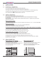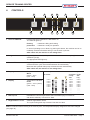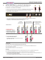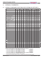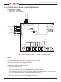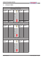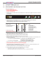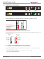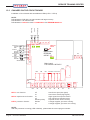
1
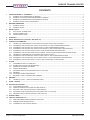
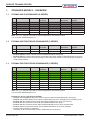
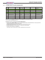
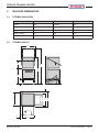
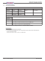
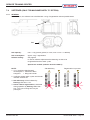
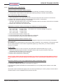
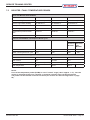
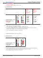
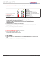
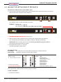
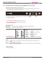
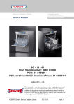
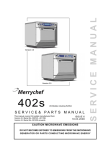
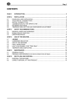
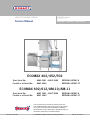
SERVICE TRAINING CENTER
HOBART GmbH
Service Manual
EFFICIENT – RELIABLE – INNOVATIVE
An ITW-Company
ECOMAX 402/452/502
Start Serial No.:
Facelift as of Serial No.:
8663 0001 – 8663 3999
8663 4000
EEPROM: 897547-6
EEPROM: 897547-17
ECOMAX 602/612/AM-10/AM-11
Start Serial No.:
Facelift as of Serial No.:
8657 1001 – 8667 2999
8657 3000
EEPROM: 897547-6
EEPROM: 897547-17
This document is produced for internal use only.
The detailed settings and servicing must be carried
SERVICE TRAINING CENTER
CoNTENTS
1.
STANdARd ModElS – oVERVIEw ..................................................................................................................................... 3
..............................................................................................................
........................................................................................
.........................................................................................
...................................................................................................................
2.
MAChINE dIMENSIoNS ........................................................................................................................................................ 5
........................................................................................................................................................
........................................................................................................................................................
3.
INSTAllATIoN ....................................................................................................................................................................... 6
......................................................................................................................................
................................................................................................................................................
.................................................................................................................................................
4.
CoNTRolS ............................................................................................................................................................................. 7
5.
INITIAl BooSTER fIll (fACElIfT SEE pAGE 32) ............................................................................................................ 8
6.
hydRAulIC SChEMATICS ................................................................................................................................................... 9
..............................................
..............................
............................................
......................
..........................................
............
......................................................................
..................................
.........................
............................................
7.
fIllING ................................................................................................................................................................................. 16
........................................................................................................................
...............................................................................................................
..........................................................................................................................
..............................................................................................................................................
.......................................................................................
..................................................................................................................................................................
..........................................................................................................................
........................................................................................................
8.
wAShING .............................................................................................................................................................................. 22
...................................................................................................
9.
hood – dETAIlS ................................................................................................................................................................. 23
10. ElECTRoNIC CoNTRol ..................................................................................................................................................... 24
............................................................................................................................................
..............................................................................................
............................................................................................
..................................................................
..........................................................................................
11. doSAGE TIMES ................................................................................................................................................................... 31
12 fACElIfT fEBRuARy 2011 ................................................................................................................................................ 32
...................................................................................................
..............................................................................................................................
......................................................................................................................
SERVICE TRAINING CENTER
1.
STANdARd ModElS – oVERVIEw
1.1
ECoMAx 402 GlASSwAShER (G-SERIES)
No.
device Code
EEpRoM1)
program
No. (lEd)
programs
Racks/hr.
Glasses/hr.
wiring
diagram
Racks/hr.
Glasses/hr.
wiring
diagram
Racks/hr.
Teller/hr.
wiring
diagram
Ecomax 402-10
Ecomax 402-12
Ecomax 402S-10
Ecomax 402S-12
Ecomax 402-20
Ecomax 402S-20
Note: The green
1)
1.2
ECoMAx 452 fRoNTdooR-dIShwAShER (f-SERIES)
No.
device Code
EEpRoM
program
No. (lEd)
programs
Ecomax 452-90
Ecomax 452-91
Ecomax 452-90
Ecomax 452-91:
caster at the rearside.
1.3
ECoMAx 502 fRoNTdooR-dIShwAShER (f-SERIES)
No.
device Code
EEpRoM1)
program
No. (lEd)
Ecomax 502-10
Ecomax 502-12
Ecomax 502S-10
Ecomax 502S-12
Ecomax 502-20
Ecomax 502S-20
7
Ecomax 502-21
Ecomax 502-30
Ecomax 502-141
Note: The green
1)
Remarks for device code Ecomax 402/502:
Ecomax -10/-12 (without "S")
Ecomax -12
Ecomax -20
Ecomax -21
Ecomax -30
Ecomax -141
S means that a softener is integrated.
S
programs
SERVICE TRAINING CENTER
1.4
ECoMAx 602/612 hood-dIShwAShER
No.
device Code
EEpRoM1)
program
No. (lEd)
programs
Ecomax 602 -10 /
AM-10 / AM-11
Ecomax 602 -11
Ecomax 602S -11
Ecomax 612 -10
Ecomax 612S -10
7
Ecomax 612 -40
Ecomax 612 -41
Ecomax 612 -141
Note: The green
1)
Remarks for device code Ecomax 602/612/AM10/AM-11:
Ecomax 602-10/AM-10/AM-11
Ecomax 602-11/all 612
Ecomax 612-40
S means that a softener is integrated.
S
Racks/hr.
wiring
diagram
SERVICE TRAINING CENTER
2.
MAChINE dIMENSIoNS
2.1
ECoMAx 402/452/502
dimensions (mm)
Ecomax 452
ECoMAx 602/612
635
107
635
821
107
200*
860*
1480*
1960*
440
713
740
2.2
Ecomax 402
Ecomax 502
SERVICE TRAINING CENTER
3.
INSTAllATIoN
3.1
ElECTRICAl CoNNECTIoN
3.2
wATER CoNNECTIoN
The machines must be operated with potable water.
for water with an extremely high mineral content an external demineralization is strongly
recommended.
Machines without softener:
max. 60°C
Machines with softener:
max. 60°C
line flow Ecomax 402-10 / 402-12 / 502-10 / 502-12 / 602-10 / AM-10 / AM-11 (without rinse pump M2):
below 2 bar, provide a rinse pump at site.
above 6 bar, provide a pressure reducing valve.
All other models (with rinse pump):
Important:
less than 0.8 bar.
above 6 bar, provide pressure reducer at source.
A
not kink or cut
dRAIN CoNNECTIoN
Machine without drain pump
max. 100 mm
Machine with drain pump (optional)
max. 650 mm
3.3
SERVICE TRAINING CENTER
4.
CoNTRolS
2
2
H1
1
H2
4
5
6
7
3
H3
1
H4
oN/STop
permanent
After switch off, the machine is not voltage free!
2 program buttons
1
2
3 drain/off button
After switch off, the machine is not voltage free!
4 display
5 display
6 Salt required
7 Regeneration indicator
Note:
Temperature indication
wash
Temperature indication
Rinse
Tank Temp. B2
Booster Temp. B1
all models
all models model
except
-402
-402
only
SERVICE TRAINING CENTER
5.
INITIAl BooSTER fIll (fACElIfT SEE pAGE 32)
before
H17
H16
H15
H14
.
☞
H27
H26
H25
H24
☞
1.
2. Push program
3.
three times.
lEd allocation:
4.
ATTENTIoN:
S03
Remarks:
<l1.0
l1.0
for machines with pressure booster:
for machines with pressure-less booster:
0
SERVICE TRAINING CENTER
6.
hydRAulIC SChEMATICS
6.1
lEGENd of CoMpoNENTS foR ECoMAx 402/502 (ECoMAx 452: SEE pAGE 3)
Ecomax
402
-10
402S
-12
-10
-12
402
402S
-20
-20
502
-10
502S
-12
-10
-12
502
502S
-20
-20
B1
Temperature sensor booster
X
X
X
X
X
X
X
X
X
X
X
X
B2
Temperature sensor tank
X
X
X
X
X
X
X
X
X
X
X
X
B3
Pressure transmitter booster
---
---
X
X
X
X
---
---
X
X
X
X
B4
Pressure transmitter tank
X
X
X
X
X
X
X
X
X
X
X
X
E1
Booster heating
5.50 kW
400/3/N/PE 3x13A/3x16A
---
---
---
---
---
---
A
A
A
A
---
---
E1
Booster heating
230/1/N/PE 1x25A
3.70 kW
---
---
---
---
---
---
---
---
---
---
A
A
E1
Booster heating
230/1/N/PE 1x20A
3.70 kW
---
---
---
---
X
X
---
---
---
---
---
---
E1
Booster heating
1.80 kW
230/1/N/PE 1x13A/1x16A
A
A
A
A
A
A
---
---
---
---
X
X
E2
Tank heating
X
X
X
X
X
X
X
X
X
X
X
X
X
X
X
X
X
X
---
---
---
---
---
---
---
---
---
---
---
---
X
X
X
X
X
X
---
---
X
X
X
X
---
---
X
X
X
X
X
X
X
X
X
X
X
X
X
X
X
X
1.80 kW
M1 Wash pump
C1 5.0 µF
0.25 kW
M1 Wash pump
C1 10.0 µF
0.37 kW
M2 Rinse pump
C2 4.0 µF
0.14 kW, 0.6A
M3 Rinse aid dispenser
M4 Detergent dispenser
Kit
X
Kit
X
X
X
Kit
X
Kit
X
X
X
M5 Drain pump
Kit
X
Kit
X
X
X
Kit
X
Kit
X
X
X
S1
Reed-switch – hood/door
X
X
X
X
X
X
X
X
X
X
X
X
S2
Impeller
---
---
X
X
---
X
---
---
X
X
---
X
S3
---
---
X
X
---
X
---
---
X
X
---
X
Y1
---
---
X
X
X
X
---
---
X
X
X
X
Y1
X
X
---
---
---
---
X
X
---
---
---
---
Y3.1 Valve resin
---
---
X
X
---
X
---
---
X
X
---
X
Y4.2 Switching valve softener
---
---
X
X
---
X
---
---
X
X
---
X
1
X
X
X
X
X
X
X
X
X
X
X
X
2
---
---
X
X
X
X
---
---
X
X
X
X
X
X
---
---
---
---
X
X
---
---
---
---
---
---
X
X
X
X
---
---
X
X
X
X
3
Pressure-less booster
Pressure booster
X
X
---
---
---
---
X
X
---
---
---
---
4
Wash arms
X
X
X
X
X
X
X
X
X
X
X
X
5
Rinse arms
X
X
X
X
X
X
X
X
X
X
X
X
6
Salt chamber
---
---
X
X
---
X
---
---
X
X
---
X
7
Resin
---
---
X
X
---
X
---
---
X
X
---
X
Notes: A
drain pump
402
drain pump
402S
drain pump
502
drain pump
502S
detergent dispenser
01-240784-1
01-510154-1
01-240785-1
01-510153-1
402/502 01-240786-1
SERVICE TRAINING CENTER
6.1.1
SChEMATIC foR ECoMAx 402-10/502-10/502-30/502-141 (wITh pRESSuRE BooSTER)
4
5
S1
2a
Y1
15 l/min
5
4
1
B4
3a
B1
B2 1E2
E1
M1
Booster draining
Drain
6.1.2
M3
SChEMATIC foR ECoMAx 402-12/452-90/502-12 (wITh pRESSuRE BooSTER)
4
5
S1
2a
Y1
15 l/min
5
4
1
3a
B1
B4 B2 1E2
M4
M1
M5
Drain
E1
Booster draining
M3
SERVICE TRAINING CENTER
6.1.3
SChEMATIC foR ECoMAx 402-20/452-91/502-20/502-21 (wITh pRESSuRE-lESS BooSTER)
Note: Ecomax 452-91
4
5
S1
2
5 l/min
Y1
5
4
1
M3
B4 B2
3
B1
E2
M4
B3
E1
M1
M5
M2
Booster draining
Drain
6.1.4
SChEMATIC foR ECoMAx 402S-10/502S-10 (wITh pRESSuRE-lESS BooSTER)
4
5
S1
S2
2
5 l/min
5
4
1
M3
3
B1
B4 B2 1E2
6
Y4.2
B3
E1
M1
S3
7
Booster draining
Drain
Y3.1
M2
Y1
SERVICE TRAINING CENTER
6.1.5
SChEMATIC foR ECoMAx 402S-12/402S-20/502S-12/502S-20 (wITh pRESSuRE-lESS BooSTER)
4
5
S1
S2
2
5 l/min
5
4
1
M3
3
B1
B4 B2 1E2
M4
6
Y4.2
B3
E1
M1
S3
7
M5
Booster draining
Drain
Y3.1
M2
Y1
SERVICE TRAINING CENTER
6.2
lEGENd of CoMpoNENTS foR ECoMAx 602/612/AM-10/AM-11
Ecomax
602-10
602-141
Ecomax
602-11
Ecomax
602S-11
Ecomax
612-10
Ecomax
612S-10
AM-10
AM-11
B1
Temperature sensor booster
X
X
X
X
X
X
X
B2
Temperature sensor tank
X
X
X
X
X
X
X
B3
Pressure transmitter booster
---
X
X
X
X
---
---
B4
Pressure transmitter tank
X
X
X
X
X
X
X
E1
Booster heating
5.50 kW
A
---
---
---
---
A
A
E1
Booster heating
6.10 kW
---
A
A
A
A
---
---
Booster heating
4.10 kW
Multiphasing 230/50/1 25A
---
X
X
X
X
---
---
E2
Tank heating
X
X
X
X
X
X
X
M1
Wash pump
0.40 kW/12.5 µF
X
X
X
---
---
X
X
Wash pump
0.73 kW/16 µF
---
---
---
X
X
---
---
---
X
X
X
X
---
---
X
X
X
X
X
X
X
X
X
X
X
X
X
X
2.50 kW
M2
Rinse pump
M3
Rinse aid dispenser
M4
Detergent dispenser
M5
Drain pump
S1
Reed-switch – hood
S2
Impeller
X
X
X
X
X
X
X
X
---
---
X
---
X
---
---
S3
---
---
X
---
X
---
---
Y1
---
X
X
X
X
---
---
Y1
X
---
---
---
---
X
X
Y3.1 Valve resin
---
---
X
---
X
---
---
Y4.2 Switching valve softener
---
---
X
---
X
---
---
1
X
X
X
X
X
X
X
2
---
X
X
X
X
---
---
2a
X
---
---
---
---
X
X
---
X
X
X
X
---
---
Pressure booster
X
---
---
---
---
X
X
4
Wash arms
X
X
X
X
X
X
X
5
Rinse arms
X
X
X
X
X
X
X
6
Salt chamber
---
---
X
---
X
---
---
7
Resin
---
---
X
---
X
---
---
3
Pressure-less booster
Notes:
A
drain pump
602/AM-10-11
detergent dispenser
602/AM-10-11
01-246480-1
01-240784-1
SERVICE TRAINING CENTER
6.2.1
SChEMATIC foR ECoMAx 602-10/602-141/AM-10/AM-11 wITh pRESSuRE BooSTER
S1
4
2a
5
Y1
15 l/min
5
1
4
M4 only AM-11
M4
B4
B2
1E2
M1
3a
B1
E1
Drain
6.2.2
M3
Booster draining
SChEMATIC foR ECoMAx 602-11/612-10/612-40/612-41 wITh pRESSuRE-lESS BooSTER
S1
4
2
S2
5
5 l/min
1
M4
B4
B2
B3
1E2
M3
M1
3
B1
1E1
M5
DRAIN
booster draining
M2
Y1
SERVICE TRAINING CENTER
6.2.3. SChEMATIC foR ECoMAx 602S-11/612S-10 wITh pRESSuRE-lESS BooSTER
S1
2
S2
4
5
5 l/min
1
M4
B4
B2 1E2
B3
Y4.2
M3
6
M1
7
S3
3
B1
1E1
Y3.1
M5
Drain
Booster draining
M2
Y1
SERVICE TRAINING CENTER
7.
fIllING
7.1
wATERBREAk wITh flowMETER
200 impulses per
liter.
100 ml
All Ecomax machines with "S"
Ecomax 402-20 / 502-20 /
602-11 / 612-10 / 612-40 / 612-41
Flowmeter
Water flow
Connection for
filling supply
Water flow
Connection for
filling supply
Overflow
Overflow
Water for regeneration
Fresh water to booster or softener
Blind plug
Fresh water to booster or softener
7.1.2. douBlE-BAll BACkflow pREVENTER
(402-10/-12 / 452-90 / 502-10/-12 / 602-10 / AM-10 / AM-11) have
Ecomax 452-91
Overflow
Water flow
connection for
filling supply Y1
Fresh water to booster
SERVICE TRAINING CENTER
7.2
pRESSuRE TRANSMITTER B3/B4
output Voltage
pressure Transmitter B3 Booster (if installed)
85 °C
output Voltage *
pressure Transmitter B4 Tank
* Additions for pressure transmitter B4 (tank):
Ecomax
Tank heating oN
Tank filled
Tank heating oN
while washing
NoTE:
pCB detail
Transmitter Arrangement
+
0V
5
Press. Transmitter B3
Booster
Voltage Signal from Transmitter
6
0
+5 V
7
+
+5 V
B3
Pressure transmitter
Booster (not for Ecomax
402-10/-12, 502-10/-12,
X14
Temp. Probe B2
Tank
1
Temp. Probe B1
Booster
0V
8
Press. Transmitter B4
Tank
Voltage Signal from Transmitter
10 9
0
B4
Pressure transmitter
Tank
NoTE:
5V
x14 pin 5 (+5 V) and x14 pin 6 (0 V) pressure transmitter booster B3,
and x14 pin 9 (0 V)
B4.
B3,
x14 pin 8 (+5 V)
x14 pin 7 (+) and x14 pin 6 (0 V) pressure transmitter booster
x14 pin 10 (+) and x14 pin 9 (0 V)
B4.
If the sensor B3, B4 is outside the "normal" range (> 4.0 V / < 0.3 V), then the control is switched off.
SERVICE TRAINING CENTER
7.3
doSING EquIpMENT
dispensers
Ecomax
part No.
delivery Rate
hose Inside
detergent
Rinse aid
pre-Adjusted Values
detergent
Rinse aid
dosage
detergent
Rinse aid
y1 or rinse pump M2.
M1 pump.
.
end of wash cycle.
SERVICE TRAINING CENTER
7.4
SofTENER (oNly foR MAChINES wITh "S" opTIoN)
7.4.1
GENERAl
y3.1
Salt capacity:
Salt consumption:
Softener setting:
In case of softener replacement the fastening nut has to be
Special tool needed (softener wrench 775920-1)
NoTE:
Active softener regeneration is indicated
during operation by
prolonged.
SERVICE TRAINING CENTER
7.4.2
SofTENER ChECk pRoCEduRE
what you need to verify the softener function:
how, respectively, where to measure?
Adjustment of softener setting according to the hardness of incoming water:
Approximate values if softener function is o.k.:
for example:
further steps:
immediately after the program cycle has ceased.
Never run the softener test program at the beginning of the herein described procedure because it
rect.
proceed as follows in case of too high hardness and/or conductivity values:
y4.2
chloride content is at an acceptable level to prevent corrosion.
SERVICE TRAINING CENTER
7.5
BooSTER / TANk / TEMpERATuRE pRoBES
parts with Booster part Numbers
Ecomax 402
Ecomax 452/502
Ecomax 602/612
Booster Volume/water Consumption Rinse Cycle
402
452/502
602
pressure pressureBooster less
Booster
Tank Volume/Tank heating
402
452/502
602
NoTE:
If one of the temperature probes (B1/B2) is out of "normal" range (>99 °C approx. /< °C) , then the
control is switched off. Service, customer, or machine selection menu can be still opened.
The probes can be checked in the service menu (see section 10.2 Service diagnostics on page
25).
SERVICE TRAINING CENTER
8.
wAShING
8.1
TEChNICAl dATA – wASh puMp/RINSE puMp
ModEl
part No.
Voltage / freq. / phases
Current
Capacitor
power
Impeller
Ecomax 602
AM-10/AM-11
Ecomax 612
Ecomax 402
Ecomax 452/502
Ecomax 602/
AM-10/AM-11
The Service kits include:
Ecomax 612
Ecomax
602S/602-11, 612(S)
402S-10/402S-12,
402-20/402S-20
502 same codes
NoTE:
part No.
Voltage / freq. / phases
Current
Capacitor
power
Impeller
SERVICE TRAINING CENTER
hood – dETAIlS
60
3
6
Y
X
hood lift handle support
6
Spring bolt (for all models):
883683-2 x
y
Adjustment of tension springs
non-insulated hood
Tension spring:
883636-3
A
9.
tion or closes.
Too much spring force:
cycle.
Make sure that in "stand-by" position, the hood
neither opens nor slowly closes.
SERVICE TRAINING CENTER
10.
ElECTRoNIC CoNTRol
10.1 CuSToMER SETTINGS
Requirements: Machine off and hood/door open.
☞
SETTING dETAIlS:
left display
Right display
detergent
dosage Time
Rinse Aid
dosage Time
1. AdjuSTMENT of dETERGENT doSAGE quANTITy (lEd h10 on):
☞
☞
2. AdjuSTMENT of RINSE AId doSAGE quANTITy (lEds h10 and h11 on):
☞
☞
3. AdjuSTMENT of wATER hARdNESS
☞
☞ CloSE
4. dETERGENT SuCTIoN hoSE
☞
☞
5. RINSE AId SuCTIoN hoSE
☞
☞
6. INITIAl BooSTER fIll
☞
To ExIT ThE MENu:
☞
water
hardness
SERVICE TRAINING CENTER
10.2 SERVICE dIAGNoSTICS (fACElIfT SEE pAGE 32)
Requirements: Machine off and hood/door open.
☞
1. INpuT SIGNAlS
on
1
h29 and h19
h28 and h18
S1 = 1
B1
B3
SETTING dETAIlS:
Input
signals
B1
B3
S8
S7
S6
S5
S4
S3
S2
S1
☞
☞
B2
ok.
B4
h20
ok.
SERVICE TRAINING CENTER
2. ouTpuT CoNTRol (
SETTING dETAIlS:
Control outputs
Ecomax:
k1/E1
M2
M5
y1
y4.2
M4
y3.1
M3
k2/E2
M1
☞
Relay 1
☞
☞
3. INITIAl BooSTER fIll
SETTING dETAIlS:
☞
☞
h20
Control outputs
Ecomax:
k1/E1
y1
M5
M4)
M3
k2/E2
M1
SERVICE TRAINING CENTER
4. SwITChING fuNCTIoNS
SETTING dETAIlS:
Switching
functions
S10
S09
S08
S07
S06
S05
S04
S03
S02
S01 Thermostop booster
☞
activated lEd on
deactivated lEd off
☞
☞
☞
5. TEST ModE opERATIoN uNIT (
☞
To ExIT ThE MENu:
output control
☞
door.
☞
BAE
Switching functions
SERVICE TRAINING CENTER
10.3 MAChINE TypE SETTING (fACElIfT SEE pAGE 32)
Requirements: Machine off and hood/door open.
☞
ExAMplE:
1 is indicated by lEd h10
5 is indicated by
1. pRoGRAM NuMBER SElECTIoN
☞
ExCEpTIoN:
of the currently programmed program number is
☞
SETTING dETAIlS:
left display
Right display
program Number Selection
program
Number
10
09
08
07
06
05
04
03
02
01
To ExIT ThE MENu:
☞
Machine
Type
SERVICE TRAINING CENTER
10.4 SofTENER TEST pRoGRAM (oNly MAChINES wITh "S" opTIoN)
Requirements: Machine off and hood/door open.
☞
☞
☞
2. SofTENER TEST pRoGRAM (
☞
SETTING dETAIlS:
left display
Right display
Sequential
operation
10.
9. Pause
8.
7. Pause
6.
5. Pause
4.
3. Pause
2.
1.
Notes:
opened.
To ExIT ThE MENu:
☞
details
SERVICE TRAINING CENTER
10.5 pRINTEd CIRCuIT BoARd (fACElIfT SEE pAGE 34)
B2
TEMP. PROBE
BOOSTER
B1
12
11
9
10
8
7
6
S3 SALT DEFICIENCY
S2 IMPELLER SWITCH
5
4
3
PE
L1
3
4
5
I
N
6
P
7
1
8
A1
TEMP. PROBE
TANK
SLOT:
E-EPROM (897547-6)
X14
B3
PE
X13
9 10
O
U
T
PRES. TRANSMITTER
BOOSTER
P
B4
O
U I
T N
PRES. TRANSMITTER
TANK
2
1
S1 DOOR SWITCH
fitting position of board:
LED 1
2
X0
X15
1
1
OPERATION PANEL
RL1
RL2
RL9
RL8
RL7
RL6
RL5
RL4
RL3
L
1
L
1
L
1
L
1
1
N
3 2
N
3 2
N
3 2
N
3 2
2
X8
X7
X6
X5
X4
X3
LED 1
NoTE:
3
1
EEpRoM 897547-6 / 897547-17 (Ecomax facelift) must be ordered separately.
L
1
L
1
N
3 2
X9
N
3 2
L
1
N
3 2
X10
3
L
1
2
N
3 2
RL10
1
N
1
X2
X1
SERVICE TRAINING CENTER
11.
doSAGE TIMES
Ecomax 402 (3 lEds)
Rinse volume per cycle: 2.50 l
detergent
pump
3.00 l/h
Rinse Aid
pump
0.40 l/h
Ecomax 452/502 (3 lEds)
Rinse volume per cycle: 2.90 l
detergent
pump
3.00 l/h
Rinse Aid
pump
0.40 l/h
Ecomax 602/612 (3 lEds)
Rinse volume per cycle: 2.90 l
detergent
pump
3.00 l/h
Rinse Aid
pump
0.40 l/h
SERVICE TRAINING CENTER
12
fACElIfT fEBRuARy 2011
12.1 NEw EquIpMENT ANd pRoGRAM fuNCTIoNS
Ecomax 402/502: 8663 4000
Ecomax 602/612/AM: 8657 3000
Ecomax 702: 8656 1001
display panel:
also displayed.
red instead of green. Temperature values are
70
65
60
55
50
45
85
80
75
70
65
60
Implementation of new software:
program Number Selection
program
Number
Machine
Type
10
09
08
07
06
05
04
03
02
01
Machines without drain pump:
pressure booster
wash tank is reached
rinse pump
booster is reached
SERVICE TRAINING CENTER
12.2 TEMpERATuRE ModIfICATIoN
☞
☞
TEMpERATuRE SETTING (f02 ANd f05): (
rinse temperature display.
Tank Temp. B2
all models
F02= >70°C
F02= >65°C
F02= >60°C
F02= >55°C
F02= >50°C
F02= >45°C
-----------------------------
Booster Temp. B1
all models
except
-702
F05= >85°C
F05= >80°C
F05= >75°C
F05= >70°C
F05= >65°C
F05= >60°C
-----------------------------
☞ To change the setting of the wash
☞ To change the setting of the rinse
☞
70
65
60
55
50
45
85
80
75
70
65
60
70
65
60
55
50
45
85
80
75
70
65
60
SERVICE TRAINING CENTER
12.3 ChANGES oN ThE CIRCuIT BoARd
NoTE:
5
1
3 cannot be used in combination
2
S1
1
Salt deficiency
Fill level
Door switch
2
EEpRoM 897547-17.
2
S3
S2
1
1
1
X13
Part number
EEPROM
897547-17
+
B2 Temperature
PE
LED 3
X0
L1
1
1
sensor
TANK
B1 Temperature
sensor
BOOSTER
X15
Slot for BAE A2
1
Main board:
Part number: 897545-5
RL1
RL2
RL9
Rl8
RL7
RL6 RL5
RL4 RL.3
Booster heating
X4
X3
1
X5
N
N
X6
N
X7
N
NoTE:
X8
N
LED 3
X9
N
LED 2
N
N
X10
L
1
IN OUT
1
L
1
L
L
L
L
L
L
K1
RL10
LED 1
N
o
transmitter
BOOSTER
X14
B3 Pressure
observe
notch
+
transmitter
TANK
o
B4 Pressure
LED 1 LED 2
X2
X1
SERVICE TRAINING CENTER
NoTES
SERVICE TRAINING CENTER
An ITW-Company