1
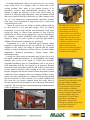
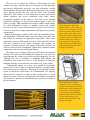
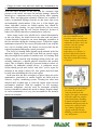
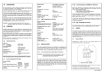
Charge air cooler maintenance considerations – what you must do.
Today’s emphasis on fuel economy and
exhaust emissions places a great deal of
responsibility on regulators, engine builders
and owners. Regulators dictate emission
limits to engine manufacturers who then
build compliant products for the market
place. However, the legal responsibility for
continued emissions compliance lies with
the engine owner and maintenance of the
Technical File and proof of adherence to
recommended
maintenance
schedules
should ensure that any emissions audit goes
smoothly.
Diligent record-keeping and the use of original-equipment rather than grey-market or will-fit parts can lead
to the assumption that an engine will maintain advertised fuel consumption and emission limits throughout its
useful life. This may be the case with normally-aspirated engines but they are increasingly rare in emissionscompliant marine propulsion and auxiliary applications. Turbocharging and charge-air cooling are now the
norm as, together, they facilitate improved combustion air management for reduced exhaust emissions.
The charge air cooler (often called an after-cooler or inter-cooler) permits a significant amount of heat to be
removed from the combustion air after it leaves the turbocharger and before it enters the engine combustion
chambers. This cooled air has two effects. Firstly, it can reduce combustion temperature so that the production
of NOx is lowered. Secondly, it increases the combustion air density (more oxygen) so that more fuel can be
burned efficiently in the finite space of the combustion chamber therefore allowing the engine to produce
even more power. Engine manufacturers establish the power output of the engine based on its mechanical and
thermal design, duty cycle and ability to comply with mandated emissions limits.
In marine applications, charge air coolers use raw (sea or lake)
water, jacket water or a separate circuit of fresh water as the
cooling medium. Raw water is less popular because of its
potentially corrosive and sediment-laden properties that can
damage or impair the efficiency of the cooler. Jacket water, by
nature of its relatively high temperature, limits the amount of heat
that can be removed from the combustion air. More common is the
use of a low-temperature, thermostatically controlled, separate
fresh water circuit sometimes in stage-series with a jacket water
cooled charge air cooler.
Charge air cooler cores are similar to vehicle radiators and can
be tube and fin or bar and plate design. They are densely
constructed to resist high thermal and mechanical loads while
having the ability to remove large amounts of heat from the
combustion air after it passes through the very hot turbocharger.
For example, a modern 4500bKW rated medium-speed engine
requires a charge air cooler capable of removing approximately
2000kw of heat from the combustion air at full load.
Encasement in a cast or fabricated metal housing makes
superficial visual inspection of the core difficult. As a result the
condition of the cooler core might be ignored until the engine
exhibits a related performance problem such as elevated exhaust
temperature, decreased performance, exhaust smoke and/or
turbocharger surge.
A charge air cooler passes an enormous mass of air on its way to
the engine combustion chambers. In our 4500bKW rated engine
example, this can be in the region of 27,000 cubic meters/hr.
Suspended machinery space air contaminants, such as oil mist or
solid particulates that are not trapped by an upstream filtration
system can easily accumulate on the air side of the core and reduce
its heat transfer efficiency while causing an air flow restriction.
Engines equipped with closed crankcase fumes absorption systems
usually have more stringent cooler core cleaning schedules as they
tend to foul more quickly due to residual oil-mist passing through
the fitted micronic air filter element. Poor coolant condition can
also cause the very narrow channels inside the cooler tubes to
become restricted or blocked entirely, also reducing its heat transfer
capability. The core therefore requires monitoring and maintenance
on the air and water sides.
The charge air cooler core on
this high-speed marine diesel is
located under the black cast
metal housing on the top of
engine. The core is accessible by
removing the top of the housing
and disconnecting the air and
cooling connections. The closedcrankcase ventilation system
requires that the core is
monitored intensively for
efficiency and cleaned regularly
to preserve engine performance
and emissions compliance.
This charge air cooler core,
removed from a high-speed engine
after approximately 4000hrs
operation, is heavily fouled on the
air side with oil residue from the
closed crankcase ventilation
system. Its heat transfer capability
is reduced by approximately 60%
resulting in higher engine fuel
consumption, elevated exhaust
temperatures and impaired
performance. Removal and
cleaning each 1000hrs of operation
is now part of the owner’s
maintenance schedule.
The best way to evaluate the efficiency of the charge air cooler
without removing it from the engine is to measure the air temperature
and pressure differentials across the core with calibration- certified
instrumentation. Measuring the differential temperature of the cooling
water passing through the core will also help with secondary
diagnostics. This practise is well understood by most professional
marine engineers and service technicians using either sensors
permanently installed on the engine or ones that can be attached
temporarily. Readings are always taken with the engine as near fullload as possible. Many medium-speed engine builders install charge
air cooler differential switches or analogue sensors that connect
directly to the ship’s alarm and monitoring system to warn of need to
service the core before engine performance and longevity are possibly
compromised.
Engine manufacturers publish specific data for acceptable pressure
and temperature differential limits across the charge air cooler core
and should be consulted for appropriate information. These limits
might allow pressure differentials of between 150% and 300% of testbed (new condition) levels before inspection and cleaning are
required. Operating engines with higher differential pressures can
result in increased fuel consumption, higher than permitted exhaust
temperatures and emissions and engine damage.
The engine service manual will provide safe practise and required
clearances for removing and handling the charge air cooler core. It is
important that the engine room layout provides adequately for this.
Although the core is designed to withstand high thermal and
mechanical stress when in service, it is not designed for improper
handling. Damage to fins and tubes can result in very costly repairs.
Contaminated charge air cooler cores should be thoroughly
inspected for obvious signs of mechanical damage or leakage before
the cleaning process commences. Photographic records and a written
report on superficial observations are recommended. For shipping
they need to be secured to a pallet or other carriage device to avoid
damage in transit. If heavily oil-fouled the core should be wrapped in
heavy plastic or placed in a containment tray to prevent oil escape to
the environment.
The manufacturer of the host
8000kw engine for this charge air
cooler core recommends servicing
when the pressure differential on
the air side reaches 150% of new.
Heavy deposition of airborne dust
resulted in a pressure differential
of almost 500% of new before it
was removed for cleaning. The
engine was in operational distress
with significant cost to the owner
and the environment.
This graphic shows a duplex
charge air cooler core that must
be fully disassembled for cleaning
and pressure testing. Reduced air
velocity between the individual
cores allows rapid contaminant
deposition that cannot be removed
by superficial cleaning. New
gaskets and seals must be used
during reassembly.
Charge air cooler cores must not, under any circumstances, be
cleaned with a commercial pressure washer. At best, this will only
clean the outer structure of the core and the extremely high
pressure at the nozzle can cause fin and tube damage. Instead it
should go to a competent cooler servicing facility where cleaning
tanks, filters and appropriate chemical solutions are available to
remove accumulated foulings from the air and water sides in an
environmentally sound manner. If the core is of the duplex type
where individual sections are bolted together they should be
separated before cleaning. Air gaps between the cores are more
prone to plugging than the core sections themselves because of
reduced air velocity that allows contaminants to settle out.
Some charge cooler cores should not be cleaned ultrasonically
as this can destroy the bond between the tubes and end plates.
Certain ultrasonic frequencies can create damaging resonances in
the fins and tubes during the cleaning process. Consult the engine
maintenance manual for the correct procedure and do not send the
core out for cleaning unless the chosen service-provider has the
required equipment and quality control procedures.
The choice of cleaning fluids depends on the material in the fins
and tubes. Highly caustic or acidic wash fluid can corrode copper
alloys but might be acceptable for stainless-steel. All cleaning fluid
residue must be removed with thorough rinsing before the core
assembly undergoes a detailed physical inspection and possible
repair. This is normally followed by pressure-testing to ensure it’s
suitability for additional, reliable service. A competent service
facility should provide and “before” and “after” service report for
inclusion in the engine’s history file. New gaskets and seals must
be used when reinstalling the core on the engine.
In the past there has been a tendency to ignore charge air cooler
maintenance, particularly in smaller engines not fitted with an
effective, in-place, monitoring system. Cleaning has often been
deferred until overhaul time or when the engine incurs obvious
performance problems. With the emphasis on fuel economy,
emissions compliance and the need for maximum reliability
between scheduled overhauls this needs to change. Regular charge
air cooler maintenance is a very wise investment for the business
and the environment.
The duplex charge air cooler on
this new 4500bKW marine
propulsion engine is designed to
remove 2000kw of heat from the
combustion air before enters the
cylinders. Note the separate
connections for the low
temperature and high
temperature core sections. A
pressure differential switch is
fitted to provide a signal to the
ship alarm system that cleaning
is required.
For cleaning the entire charge
air cooler core assembly is
removed axially from the
engine. The engine room layout
must allow sufficient room for
removal and proper handling.
It must be designed such that
bulkheads and support posts do
not interfere with safe cooler
core removal. Appropriate
rigging combined with safe
handling procedures facilitate
core maintenance.