1
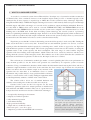
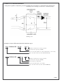
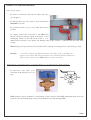
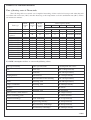
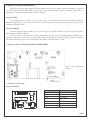
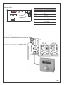
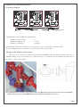
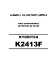
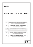
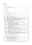
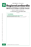
THERM
CASCADE BOILER
ROOMS
CASCADE CONTROL SYSTEM FOR THERM
TRIO 90(T), DUO 50(T), (FT), 20 and 28 (LX, LXZ, TLX,
TLXZ), 14 (X, XZ, KX, TX, TXZ, TKX) BOILERS
(with DIMS01 –TH01 automatics)
THERM CASCADE BOILER ROOMS
3/2006
THERM CASCADE BOILER ROOMS
1. WHAT IS A CASCADE SYSTEM
A cascade is a connected system of more Therm boilers. Its unique way of connection and the construction
of Therm boilers allow continuous increase of the installed output starting at 35% of nominal capacity of the
smallest boiler. If more capacity is required (up to 1MW) the cascade system has many advantages. Especially,
using Therm DUO 50(T) or TRIO 90 is highly advantageous because of the relatively little used space and the high
installed output, with all the advantages of a cascade and its continuous output modulation maintained. However,
not only DUO or TRIO boilers can be used in a cascade. THERM DUO 50(T) and THERM TRIO 90 can be
combined with other THERM boilers and in this way, the system can be adapted to the calculated heat loss of the
building and to the DHW need. In the field of heating system technology, the cascade system is a pioneering
method of optimizing installations with high output. Instead of one boiler with high capacity which would have to
work as a whole even when only little output is demanded, in the cascade system as many boilers as you need at the
moment will work. The number of boilers to work is controlled electronically.
Experience proves that 80% of time in the heating season the boiler capacity is used at only 50%. During the
entire season the boiler is used at only 30%. It means bad use and inefficient operation. As obvious, a cascade
system provides the immediate needed capacity by connecting more “small” boilers as opposed to one big boiler
with inefficient operation at small outputs. The cascade programmed control removes the troubles of setting the
optimum ration of the system capacity and heat consumption. The wide range of control enables long-time
operation with lower heating water temperatures, which reduces the losses caused by emissions and the losses
arising when the system is in the emergency mode. This enhances use of the system and makes the conditions in
the heated environment more pleasant, in other words, this improves the user’s comfort.
The consistent use of information technologies makes a control optimising the boiler room performance in
every moment possible. So far, the boiler room operation was controlled by an expensive system of cascade
controllers. Using a communication interface, which enables the information transfer among the boilers and also a
continuous output modulation of all boilers at the same time, has been a major step. It means not only that the
boilers can achieve the most efficient output at any moment of the
operation but also that there is an immediate access to current
information and possible analysis of any problem which could arise.
A today’s cascade boiler room is really intelligent equipment which
works independently, without a “fallible” man’s intervention.
The solution with a clever use of standard hardware and
software at reasonable prices is then accessible for everybody.
Cascade boiler rooms are the best response for the acute
demand for optimum solution for current problems of middle-sized
and small heat and DHW consumers. They are of a great interest to
both professionals and investors because of their basic advantages:
• exceptionally advantageous investment
• uniquely economical operation
• fully automated operation
• environment-friendly
• high operational reliability
• simple and easy technical solution
• little used space – saves floor space
• adapted for possible external DHW tank connection
The fact the cascade boiler room does
not require any special location means it
can be placed almost anywhere.
Installing boilers in the loft saves space
and removes the need of a high chimney
because of bad atmospheric conditions.
3/2006
THERM CASCADE BOILER ROOMS
It is possible to use several THERM DUO 50, 50T boiler units (up to 16 units in one cascade system, which
means the maximum output of 720 kW) or THERM TRIO 90 (up to 10 units in one cascade system, which means
the maximum output of 1 MW). A tailor-made cascade system then provides an optimum heat source and it is the
required compromise between an individual and central (external) heat delivery for flats and facilities. To sum up,
the cascade boiler rooms can be set up quickly using pre-prepared modules, they can be reconstructed while the
boiler room is fully operational, they are easy to service and maintain and they have long life; last but not least,
their surrounding remains untouched with no non-aesthetic external distribution nets. Moreover, THERM boiler
cascade can be located at almost any place. Since the start of the THERM boilers development and their cascading
in 1993, it has been attracting attention of experts both in the Czech Republic and abroad. Cascade boiler rooms
have been awarded many prestigious professional prizes, mainly because of their flexible innovations and
immediate use in the practice. Nowadays, they are the unrivalled technological top in their category, thanks to the
perfect programming and unlimited communication possibilities. If you are interested, you can get the best idea of
the cascade boiler room economy at www.thermona.cz where some examples of the real installations including the
assessment of their costs and return on investment are provided.
2. DESIGNING A CASCADE SYSTEM
When designing a cascade, it is necessary to consider the following points:
2.1
Calculate the heat need from the point of view of heat transmission of the installed heating system, which
has to correspond to the cascade capacity.
The number of boilers is to be determined in relation to this capacity.
2.2
Choose the location of heat sources.
2.3
Design the composition and the dimensions of the individual hydraulic parts of the cascade system
according to the cascade capacity.
2.4
Determine the bulk flow from the system capacity and determine the output of the main circulation pump
behind the hydraulic equalizer of dynamic pressures.
2.5
Design the flue exhaust, or a common collector.
2.6
The control, the operations and the setting of the cascade.
2.1 Calculating the number of boilers
The basic data for designing a boiler room, for choosing the wiring diagram and for dimensioning all the
equipment is the installed capacity of boilers, which is called the connecting heat output of the heat source. That is
the heat output necessary to cover the heat losses of the building and the heat needs of other appliances (DHW
heating, airing, etc.). The boiler room capacity is not just the sum of all maximum power requirements because the
heat consumption changes with time; it has to be determined individually. Norm ČSN 06 0310 provides the
calculation for these kinds of operation.
3/2006
THERM CASCADE BOILER ROOMS
1. Heating a facility with interrupted airing and DHW heating.
QPRIP = 0.7 x QTOP + 0.7 x QAIR + QDHW (W, kW)
2. Heating a facility with permanent airing or permanent technological heating.
QPRIP = QTOP + QVT (W, kW)
3. Heating a facility and DHW heating with a through-flow system with preferential DHW.
QPRIP = the higher value out of the need for heating or DHW heating.
where:
QPRIP – installed boilers capacity (total boiler room capacity) (W, kW)
QTOP – facility heat loss with local external calculated temperature (W, kW)
QAIR – heat input of air-conditioning technology (forced airing) (W, kW)
QDHW – heat input of DHW heating (W, kW)
QVT – heat input for airing or technological heating
It is recommendable to give the design of boiler room capacity great attention. The calculation of the heat
consumption and the heat loss is often underestimated and the result is a boiler room with over-dimensioned boilers
or with insufficient capacity. This leads to inefficient and uneconomical operation and useless increase of
investment costs or the heat source is considered insufficient by the user.
It is especially necessary to proceed carefully and properly when reconstruction solid fuel boiler rooms,
where the installed output of the current boilers is in almost every case over-dimensioned, sometimes by more than
100%.
2.2 Choosing the location of heat sources
It is necessary to use the diagram of the heating system to consider if a central heating system or a system of
more decentralized groups of boilers with calculated outputs is more convenient. The decentralization can be more
suitable because of easier control and lowering of hydraulic and heat losses in the system. Also, it is necessary to
decide what kind of flue exhaust will be more convenient – a common chimney or an exhaust of every individual
boiler etc. Moreover, the kind of airing needs to be considered and adapted to the kind of boilers.
2.3 Designing the individual hydraulic parts of the cascade system
Several basic technical regulations need to be observed when designing and installing a cascade system. If
these are met, you will avoid some basic mistakes that could later influence the use of the system. Especially, these
points need to be given attention:
- non-return flap valve, filter, draining and closing valve under each boiler
- hydraulic distributor + hydraulic equalizer of dynamic pressures (HEDP)
- safety device
- DHW heating solution
- the main circulation pump in the secondary circuit (see the following chapter)
3/2006
THERM CASCADE BOILER ROOMS
Non-return flap valve
There must be a non-return flap valve under each boiler in the cascade. The valve when the excess pressure is
about 20 mbar. It is installed to prevent heat losses that could be caused by the emission of heat over the heat
exchangers that are not operational at the moment.
Filter
It is strongly advisable to use filters in the system. There is a lot of dirt, impurities, rust and stone, especially
in the older heating systems. Filters prevent the dirt from getting to boilers and their damage. Filters need to be
place in the non-return valve of every boiler. Besides these filters that are located
under each boiler, there can be a system filter. This one is located in the return
branch of the primary circuit in front of the hydraulic equalizer of dynamic
pressures.
Draining valve
We recommend placing a draining valve under each boiler in the cascade.
This will be especially convenient for service technicians in cases of emergency
or even a regular check. Draining valves are related to closing valves.
Closing valves
Installing closing valves is a very good investment. These valves are located on the inlet and outlet of the
heating water from the boiler and they allow the user to close the inlet of heating water to the boiler, which then
can be easily drained using the draining valve. These valves can be used only when the boiler is disconnected and
unoperational, e.g. because of maintenance work! The valves should never be used when the boiler is running!
Hydraulic distributor + hydraulic equalizer of dynamic pressures (HEDP)
If the cascade system is to work properly, it is necessary to separate the boiler circuit and the heating circuit
because the bulk flow of boiler circuit water is variable dependent on
the number of working boilers. The bulk flow of the water in the
heating circuit also changes when mixing valves are used to regulate
independent heating zones. To separate the boiler circuit and the
heating circuit, a hydraulic equalizer of dynamic pressured HEDP
(torus) is used.
We recommend using a typified hydraulic distributor with an
integrated torus Thermset for specific connection of hydraulic parts
of Therm boiler cascade. The producer provides a wide range of
distributors that can be chosen in relation to the number and the kind of
connected boilers and the dimensions of the boiler rooms. Thermset
hydraulic distributors are produced as a left version (HEDP on the left)
and as a right version (HEDP on the right). These versions are further
divided into Thermset LINE and Thermset BACK. Thermset LINE
serves for easy connection of boilers located in a line. Thermset BACK is used to connect boilers standing in two
lines with their back to each other. This system is used in cascades installed for example in the centre of a boiler
room, where boilers are suspended on a common support frame.
3/2006
THERM CASCADE BOILER ROOMS
A diagram of equalizer of dynamic pressures including the approximate recommended ratio dimensions:
deaerating valve - heating system sensor - circulation pump
draining valve
Examples of signs of Thermset hydraulic distributor types:
DUO THERMSET BACK
180 / 4
Number of boilers in a cascade (4 units)
Total cascade capacity (180 kW)
Layout of boilers (Back - two lines with backs to each other)
Type of boilers in the cascade (Therm DUO 50)
TRIO THERMSET LINE L
360 / 4
Number of boilers in a cascade (4 units)
Total cascade capacity (360 kW)
Torus location (onthe left)
Layout of boilers (Line - in one line)
Type of boilers in the cascade (Therm TRIO 90)
3/2006
THERM CASCADE BOILER ROOMS
EXAMPLES OF THERMSET HYDRAULIC DISTRIBUTOR VERSIONS
3/2006
THERM CASCADE BOILER ROOMS
Safety system of the boiler room
The system of the heat source (a boiler room and the heating system) is directed by valid regulations (ČSN
06 0830). Its current version makes designers quite free as far as the safety precautions are concerned. The total
volume of water in the heating system changes with its
temperature. Water cannot be compressed and when
heated up its volume increases. The extra volume needs
extra space. For these reasons, expansion vessels are used
to “store” the extra volume and a safety device prevents
the system from exceeding the allowed pressure.
To calculate the expansion vessel volume, the
dimension of the safety pipings and to design the safety
valve use the calculations included in valid regulations
(ČSN 06 0830).
The volume of the expansion vessel depends on the
volume of heating media in the heating system!
When designing a new system of central heating, it
is easy to calculate the water volume. The volume is then
the sum of the volume of water in boilers, in pipings, in
heating radiators and in other parts. The data on the water
volume in individual parts are provided in project
documents of their producers and the water volume in the piping can be calculated out of the tables of piping
dimensions. Some producers of expansions vessels provide a simple application to calculate the heating media
volume in the system; such an application can usually be downloaded free from their websites.
The trouble is if we need to find out the water volume in a current (old) heating system, which is virtually
impossible given the lack of documents. When determining the water volume in current system, the experience and
comparison with new systems are used. The volume is then recalculated to 1 kW of installed heating radiators (not
the heat losses or boiler output!):
Systems with plate radiators.......................... 9 - 12 litres
Systems with sectional radiators...................14 - 16 litres
Systems with convectors................................ 7 - 9 litres
The lower value is applicable to smaller systems or to systems with forced heating water circulation and the
higher value is applicable to larger systems or to systems with gravity circulation. Be aware, this is only an
estimate, and it is necessary to proceed carefully and to consider all possible influences. Further, it is necessary to
add the volume of the water in boilers! If in doubt, it is better to consider higher volumes. Under-dimensioned
expansion vessel would cause considerable troubles with operational pressure fluctuation (which can cause an
accident), an over-dimensioned expansion vessel is “only” more expensive, but the heating system can then work
without troubles.
DHW heating
As the introduction chapter has shown, the Therm cascade can also provide a reliable and efficient solution
for DHW heating. Heating DHW is in some ways specific, which is necessary to observe. The basic rules to
calculate the DHW heating equipment are stated in valid regulations (ČSN 06 0320).
3/2006
THERM CASCADE BOILER ROOMS
Other specific points:
-
the boiler is connected to the tank via a three-way valve
(see the photo)
-
the time the three-way valve needs to reset itself must be
maximum 8 seconds
-
the connection needs to be as close under the boiler as
possible
-
the output of the boiler connected to the DHW tank
should correspond with the output of the heater or heat
exchanging surface in the tank. If the boiler is overdimensioned in relation to the heater, the heating water in this circuit is overheated and the boiler starts
cycling.
-
DHW heating can be provided by all controlled boilers. Only the controlling boilers cannot heat up a tank.
Example:
A cascade consists of 5 DUO 50 boilers. One boiler is the controlling one –
superior to the others. The other four boilers are controlled. It means all the four
boilers can be connected to a DHW tank over a three-way valve.
Terms such as a controlling boiler, a controlled boiler etc. are defined in the chapter Control.
-
the three-way valve needs to be
connected in the following way (see
fig.):
-
DHW heating is always dominant over the heating system; it means if the DHW temperature falls, the boiler
resets the valve from the heating system to the tank heater and starts heating DHW.
3/2006
THERM CASCADE BOILER ROOMS
Time of heating water in Therm tanks
The following table was created out of empirical measuring of time needed to heat up a tank when the tank
was filled with cold water (10°C) and then heated up to the temperature set be the tank thermostat (60°C). Times
are indicated in minutes.
Tank type
DHW
DHW
Heater
volume heated by capacity
[l]
°C
[kW]
OKC 40 NTR
Therm 40
Therm 55
stainless
Therm 60
Therm 100
OKC 125 NTR
OKC 160 NTR
OKC 200 NTR
OKC 200 NTRR
OKC 300 NTRR
OKC 400 NTRR
OKC 500 NTRR
OKC 750 NTRR
OKC 1000 NTRR
14
Boiler capacity [kW]
20
28
45
90
the time of tank heat-up in minutes
6
6
unsuitable unsuitable
38
36
50
50
14
22.4
10
9
55
50
25
13
9
7
58
95
120
160
210
200
292
380
470
731
958
50
50
50
50
50
50
50
50
50
50
50
17
24
24
24
24
48
72
82
98
93
100
13
25
29
38
38
48
70
91
113
175
229
9
17
20
27
27
34
49
64
79
123
161
unsuitable
14
17
22
22
24
35
46
56
88
115
unsuitable unsuitable
unsuitable
unsuitable
unsuitable
unsuitable
unsuitable
14
22
28
35
54
71
unsuitable
unsuitable
unsuitable
unsuitable
unsuitable
unsuitable
unsuitable
16
18
27
36
For DHW consumption in litres we can use the following values:
The type of facility
Some specifications
Consumption min.-max.:
flats
work days
100–110 l/person/day
weekends
140-160 l/person/day
with showers
90-110 l/person/day
with a kitchen in the building
120-130 l/person/day
hotels
including staff
130-200 l/person/day
camps, restaurants
including staff
80-100 l/person/day
lodging houses
kitchens
schools
10 l/meal
including staff
20-30 l/pupil
sports facilities with showers
50-70l/person/day
roofed swimming pools
60-100 l/customer
industrial buildings
clean workshops
20-25 l/person/day
engineering industry
35-50 l/person/day
dirty and dusty workshops
50-60 l/person/day
hot and dusty workshops
80-100 l/person/day
3/2006
THERM CASCADE BOILER ROOMS
Connecting the tank to cold water inlet
The connection must be carried out in compliance with valid regulations (ČSN 06 0830) – for safety
precautions of central heating and DHW heating, will all fittings (see fig.)
U-closing tap at the cold water inlet
Z-testing tap
K-return valve
P-safety valve
M-manometer
E-expansion vessel (recommended)
Besides these necessary fittings it is possible to fit an
expansion vessel to the cold water inlet, which will cover the DHW expansion when the tank is being heated up
and will prevent opening the safety valve. However, it is necessary to use an expansion vessel designed for this
purpose! Never can be used an expansion vessel for heating systems! (different pressures, different material…)
The tanks without a draining hole have to be fitted with T piece with a draining valve at the DHW inlet. Tank
exchanger is fitted to the heating water source (e.g. a gas boiler) and the thermostat controls DHW heating. If the
three-way valve and the pump are connected suitably, the heating water source heats up the domestic water
automatically and the DHW heating is dominant over “space” heating. To reach the demanded DHW temperature
set on the thermostat, the heating water temperature must be min. 5°C higher (15°C is recommended). Tanks work
on a pressure basis. There is a permanent water pressure in the tank. In this way, DHW can be taken to locations
with a higher pressure fall from the tank. If the DHW distribution net is long, we recommend using a circulation
system. All connecting nets need to be properly insulated.
Cold water is to be connected to the inlet marked with a blue ring or a sign "VSTUP TUV" = “DHW
INLET”. The safety valve is to be fitted according to the manual. Hot water is to be connected to the outlet marked
with a red ring or a sign "VÝSTUP TUV" = “DHW OUTLET”. The heating circuit is connected to the marked
inlets and outlets of the heater exchanger and the deaerating valve is fitted to the topmost spot.
Electrical connection of the DHW tank to the boiler
Type 14, 20, 28, DUO 50 boiler with a closing voltage of tank thermostat 24V DC are only connected with
the tank by a twisted pair (this must be a cable, not a wire!) and they require a tank thermostat with gilded
contacts. Boilers marked LO have the closing voltage of tank thermostat 230V/50Hz. With this voltage, it is
necessary to use a twin and earth cable with double insulation, to connect by protection green/yellow conductor and
to carry out protective interconnection. Boilers marked EZ/B sense the DHW in temperature in the THERM 100/B
tank by NTC resistance sensor wound in the rear part of the boiler.
The tank must be earthed with proper connection of earth conductor at the fastening bolt.
For more information on tank products go to www.thermona.cz.
2.4 Designing the system pump
It is quite easy to design the right system pump but it cannot be underestimated. An over-dimensioned pump
can cause troubles as well as an under-dimensioned one. The heat input to the central heating system and the heat
drop of water determines the needed volume of heating
water and the pump needs to provide its circulation. The
appropriate pump can be chosen from the catalogues of
producers of pumps; this pump’s characteristics should
correspond to the required capacity parameters for the
3/2006
THERM CASCADE BOILER ROOMS
transported amount. The optimum operational point is selected on the operational curve of the pump; the point
determines the pressure the pump can provide for the transported amount. This pressure is then considered when
calculating the rest of the central heating system for the hydraulic calculations of the piping. Thus, the operational
point of the pump and the operational characteristics of the system are determined. On the basis of the transport
output, the weight transported amount mdop (kg/sec) or the volume transported amount mobj (l/sec) of the pump are
set.
The basic relation of the heat usable from the heating water is expressed as a relation of the weight volume of
water, specific heat water capacity (specific heat) and temperature difference (water cooling when heat is
transferred):
Q = m dop .c.∆t
(J)
When modified, we can acquire the relation for the calculation of water weight with the set volume of heat
we can get from water when cooling it. The water weight can be calculated using this formula:
mdop =
Q
c.∆t
(kg)
where:
Q = transferred heat volume (J)
mdop = weight of water (kg)
c = water specific heat (J/kg.°K); when the water temperature is medium tm = 80 °C then c = 4230 J/kg.°K
∆t = water cooling – the difference between the inlet and the outlet temperature – after heat transfer (°C)
2.5 Designing flue exhaust
The basic guideline for calculating a common chimney is a valid norm (ČSN EN 13384-2). The calculation
of the flue exhaust carried out in
compliance with the guideline
expects a computer application
to be used for every boiler
room.
The issue of flue exhaust
is often underestimated when
reconstructions are carried out
although the norm makes it
clear that every flue exhaust
must be calculated. The
application that is often used to
calculate a common chimney is
one developed by ProTech, which also includes Therm boilers.
Some principles that have to be taken into consideration when designing a chimney:
-
maximum of four appliances can be connected to one chimney ventilation pipe. If there
are more boilers in the cascade, it is necessary to design more chimneys.
3/2006
THERM CASCADE BOILER ROOMS
-
for the calculation, the temperature conditions of the chimney and its pressure conditions
are to be assessed individually.
-
the chimney must be designed for all extreme conditions, i.e. for summer and winter, for
minimum and maximum operation etc.
-
DUO 50 T boilers cannot be connected to a common flue collector! (type B appliance) If
this condition is not met, the flue can escape to the neighbouring boiler over the exhaust
interrupter! The flue exhaust of DUO 50 T boilers needs to be carried out independently,
using ∅80mm piping. The maximum possible length of the exhaust is then 5m.
The boilers used most frequently for cascades are Therm Duo 50(T) and Trio 90 boilers. These appliances
are of type B – they have an open combustion chamber. Therefore, it is necessary to consider sufficient airing of
the boiler room!
2.6 Control, functions and setting of a cascade
Description of controls
As the cascade boiler rooms with autonomous control using an interface are extremely popular, we are
offering a new generation of this simple control that can use all the qualities of the boilers. The basic criterion was
the possible use of highly advantageous qualities of Siemens QAA 73.110 communication controller. This made
us develop new interface for the control boiler of the cascade called IU05q (when using the older Chronotherm
CX 51 MC the interface is marked IU05), which transmits information not only among the other boilers in the
cascade but also with Siemens QAA 73.110. The controller analyses the output temperature of the heating system,
therefore, the regulation software was modified and the temperature sensor of the heating system was relocated to
the torus outlet. At the same time, the communication among boilers (RS 485) has been expanded by operational
and failure information from the control boilers to be indicated in the controller; in the future it will be possible to
monitor the cascade operations from a computer. The modified interface for control boilers is marked IU04.10.
Several changes have also been done to the boiler processor with a new control panel marked DIMS01-TH01. For
the control boiler with IU05 and controlled boilers with IU04.10, software version 1.00 MB and higher is necessary
(for TRIO 90 boilers v. 1.03 MB and higher).
At the beginning of 2005 the production of Chronotherm CX 51 MC controller was finished and then it was
sold out. Currently, we are offering Siemens QAA 73.110 controller, which has similar features and qualities. A
detailed manual for this controller can be downloaded from www.thermona.cz.
For a very comfortable control of the cascade, there is a regulation system with programmable Tronic 2008E
controller. This can provide an independent control of up to 6 regulation circuits and it is able to send orders via
communication line and control the entire cascade according to their current needs. At the same time, it is able to
collect operational data from technological circuits and from the cascade and present them (e.g. using a common
serial interface RS232 or RS485, or a GSM gate or a modem) to a possible remote boiler room control centre.
Other features of this controller: remote processing of signals, simple programming, remote comfortable graphic
visualisation of parameters and their settings, data archiving and management, variable time programs etc.
Examples – versions – of typical project cases that are already available in Thermona include designs of TRONIC
2008E regulation system hw and sw equipment and they can be adapted to the specific needs of the controlled
technology, if the user wants more than the standard solution. TRONIC 2008E systems can be programmed on a
PC in WINLEDA graphic environment. This comfortable software enables designers and users – not only
programmers – to work with control program efficiently and without delays.
3/2006
THERM CASCADE BOILER ROOMS
Typical examples of TRONIC 2008E control system for cascade boiler rooms:
Version no. 1: 2 heating branches regulated by weather compensation - analogue electric actuators 0-10V
DC/24V
- safety precautions of the boiler room – safety valve; signalization of flooding, gas leaks, fire; automatic
refilling of heating circuit by solenoid valve; control of heating circuit pumps, of DHW circulation
Version no. 2: 2 heating branches regulated by weather compensation - three-point electric actuators 230V (e.g.
Komextherm)
- safety precautions of the boiler room - signalization of flooding, gas leaks, fire; control of heating circuit
pumps
Version no. 3: 3 heating branches regulated by weather compensation - 2 analogue electric actuators. 0-10V
DC/24V, 1 three-point electric actuator 230V
- safety precautions of the boiler room - safety valve; signalization of flooding, gas leaks, fire; automatic
refilling of heating circuit by solenoid valve; control of heating circuit pumps, of DHW circulation
Version no. 4: 4-6 heating branches regulated by weather compensation - analogue electric actuators 0-10V
DC/24V
- safety precautions of the boiler room - safety valve; signalization of flooding, gas leaks, fire; automatic
refilling of heating circuit by solenoid valve; control of heating circuit pumps, of DHW circulation
Communication principles and its description:
Specifications:
-
interface IU05 is in contact with interface IU04.10 via bipolar serial line (RS485)
8 bit DIP switch to set the number of boilers in the system and the operation mode
2 LED’s at IU05 signal the status of the serial communication line (RS485)
IU05 provides control of all the system in connection with:
-
regulation electronics of the control boiler DIMS01-TH01 directly
interface IU04.10 of the controlled boilers via serial line (RS 485)
controller QAA 73.110 ( TRONIC 2008 E ) using modified communication (Open-Therm)
The control boiler connected with IU05 does not allow for DHW tank heating, and these are connected to it:
-
system temperature sensor – connection to DHW temperature sensor connectors (connector X9)
system pump – connection over a closing relay to 3-way valve control terminals (connector X19)
boiler room switch (either a closing contact of auxiliary regulation or a room thermostat) – connection to
room thermostat connectors (terminal box X7)
outside temperature sensor – (terminal box X6)
Interface IU05 cooperates with Siemens QAA 73.110 and they inform each other on:
-
outside temperature
heating temperature modulation (the demanded and the real temperature of the system)
status or a failure of each boiler in the system (failure indication)
enabling or disabling of DHW tank heating for every controlled boiler
makes emergency mode possible if communication with QAA 73.110 (TRONIC 2008E) is interrupted
3/2006
THERM CASCADE BOILER ROOMS
Regulation with external controller Siemens QAA 73.110
Interface – IU05 in control boiler, IU04.10 in controlled boilers
DIMS01-TH01 automatics setting:
- Using service buttons, set parameters 3 and 4 to zero in all boilers (pump run-down and anticycling
time).
- Control boiler: SW1 Outside temperature sensor connected, parameter switch (SW1)
1, 4, 5, 6 = OFF; 2, 3 = ON, room thermostat connector interconnected
(it is possible to use the external contact for forced switch-off).
Controlled boilers: Parameter switch (SW1) 1–6 = OFF, room thermostat connector
interconnected.
If you choose this kind of regulation, QAA 73.110 carries out all calculations of the demanded heating
system temperature according to the chosen way of regulating (service setting). The value of the demanded
temperature is transferred into interface IU05, where it is processed further in view of the demanded output of the
boiler room (the ideal number of working boilers and the kind of their modulation are chosen). The information
between the control and the controlled boilers is transmitted in both ways along a serial line (RS 485) with the help
of interface IU04.10.
For the wiring between the boiler and the controller a double line is used with the max. length of 50 m and
max. resistance of 2 x 5Ω. This wiring also provides the electric supply for the controller (it does not need
batteries). To prevent any possible information transfer interference the wiring must not run in parallel with the
supply distribution wires in the building. To be able to use the regulation’s features it is necessary to connect the
outside temperature sensor THERM Q 01 into the appropriate terminal box of the control boiler.
Heating without the weather compensated regulation and without QAA 73.110
Interface – IU04.10 in control boiler, IU04.10 in controlled boilers
Setting of DIMS01-TH01 v. 2.01MB and higher:
- Using service buttons, set parameters 3 and 4 to zero in all boilers (pump run-down and anticycling
time).
Control boiler: Outside temperature sensor not connected, parameter switch (SW1) 1,
2, 4, 5, 6 = OFF; 3 = ON, room thermostat connector interconnected (it is possible to
use the external contact for forced switch-off).
-
Controlled boilers: Parameter switch (SW1) 1 – 6 = OFF, room thermostat connector
interconnected.
The heating starts when the contacts of the room thermostat or of the auxiliary control switch on the control
boiler close (if the room thermostat or the auxiliary regulation is not used, it is necessary to interconnect the
terminal connectors of the room thermostat with a jumper) – if the mode switch is set to winter mode. If the heating
system temperature is lower than the demanded temperature (control boiler temperature knob), the control boiler
and the heating system pump are activated (over the closing relay). With the help of communication the control
boiler then activates the controlled boilers according to their addresses.
When the demanded temperature is reached, it is maintained by continuous modulation of the boilers connected in
the cascade, including the control boiler. The output of the earlier activated boilers will approximate the maximum,
the last boiler (or the last two boilers) will only help to balance the output needed by more intensive modulation. If
the regulation range of the last boiler is not sufficient and the heating system temperature starts increasing, the
control boiler starts disconnecting the working boilers until the temperatures are balanced.
3/2006
THERM CASCADE BOILER ROOMS
If the heating temperature exceeds the set value more considerably (for example by opening the contact of the
night reduction), all the boilers are switched off. The system pump works for an hour after the last boiler is
switched off.
Heating with weather compensated regulation
Interface – IU04.10 (or IU05 if the communication with the controller is interrupted) in the control boiler,
IU04.10 in the controlled boilers
Setting of DIMS01-TH01 v. 2.01MB and higher:
-
-
Using service buttons, set parameters 3 and 4 to zero in all boilers (pump run-down and anticycling
time).
Control boiler: Outside temperature sensor connected, parameter switch (SW1) 1,
4, 5, 6 = OFF; 2, 3 = ON, room thermostat connector interconnected (it is possible
to use the external contact for forced switch-off).
Controlled boilers: Parameter switch (SW1) 1 – 6 = OFF, room thermostat
connector interconnected.
The boiler’s operations are the same as in the mode mentioned in paragraph 1.1, the only difference being
that the heating system temperature is set automatically according to the outside temperature (measured by the
sensor). Calculation of the demanded heating system temperature is the function of the outside temperature and the
function of K factor, which is set by the heating water temperature knob on the control panel of the control boiler,
according to the following formula:
Ttop = (20 – Text) * K + 20 oC
Ttop = heating water temperature
Text = outside temperature
System temperature reduction (only for IU04.10)
The night reduction is carried out by the change of the curve on the control boiler and its value is set by the
DHW temperature knob in the range of 0 – 30 oC (by turning from the left to the right). The value of the night
reduction is zero in the extreme left position. The night reduction starts when the contacts of the time switch,
connected to X14 connectors = tank thermostat open (DHW tank heating is not enabled in the control boiler). If
you do not use the night reduction, the connectors X14 must be connected by a jumper.
3/2006
THERM CASCADE BOILER ROOMS
DHW heating in the tank
A DHW tank can be connected to each controlled boiler in the cascade by a three-way valve. This mode starts
after tank thermostat (or auxiliary control) contacts close and this boiler is disconnected from the controlled
cascade during heating the water. When tank heating is finished the boiler is connected again if required.
CONFIGURATION OF SWITCHES
Field 1 – setting the operation mode – IU05 only as the controlling, IU04 as the controlling or the controlled.
Field 2 up to Field 5 - in the control boiler
- number of controlled boilers in the cascade
- in the controlled boiler
- the address of the rank of the boiler in the cascade
Field 6
- not used
Field 7
- in the control boiler - ON = heating system pump spin is disabled
Field 8
- in the control boiler - ON = rotation of boilers in the cascade is disabled
There has to be only one control boiler in the cascade.
The set number of controlled boilers (set on the control boiler) has to correspond to the real number of
boilers in the cascade.
Field 1
OFF
ON
FUNKCE KOTLE
IU04.10 as the controlled
IU05, IU04.10 as the
controlling
Example of an 8-boiler cascade:
Field 1
Field 2
ON
OFF
OFF
OFF
OFF
OFF
OFF
OFF
ON
ON
OFF
ON
ON
ON
OFF
ON
Field 3
ON
OFF
ON
ON
OFF
OFF
ON
ON
Field 4
ON
OFF
OFF
OFF
ON
ON
ON
ON
Field 5
OFF
OFF
OFF
OFF
OFF
OFF
OFF
OFF
Field 1
Field 8
Rank of
boiler in
cascade
1
2
3
4
5
6
7
8
the Address of the
the controlled
boiler
(Field 2– 5)
controls 7 boilers
1
2
3
4
5
6
7
the control boiler
1st controlled boiler
2nd controlled boiler
3rd controlled boiler
4th controlled boiler
5th controlled boiler
6th controlled boiler
7th controlled boiler
Anomalies
1. Serial communication failure
Each boiler which does not receive a signal from the serial line switches over to the local mode function after
1 minute.
2. Damage of temperature sensors
If a temperature sensor of the system is damaged (short circuit or disconnection) and the serial
communication among boilers continues, all boilers are started gradually and they work according to the
temperature set on the control boiler, or the temperature set in the controller. The control of boilers’ output will
operate in the whole range of their modulation.
3/2006
THERM CASCADE BOILER ROOMS
DHW heating continues in the given boiler.
If the internal sensor of the heating temperature fails, the affected boiler (control or controlled) is
disconnected from the cascade control (see the Boiler Service Manual).
If the outside temperature sensor is damaged, the system temperature control is set based on the control
boiler setting or according to the controller (see manual for the controller).
Cascade control
1. Delayed ignition
In order to avoid more boilers being ignited at the same time in response to an impact requirement for heat
increase, there is a variable time interval added to the connecting sequence of boilers in the cascade (according to
difference of the demanded and the real temperature of the heating system in the range of 20 to 180 s). Therefore,
the boilers ignite in the most suitable delay to reach the demanded temperature as soon as possible.
2. System pump
The system pump is activated just before the ignition of the first boiler in the cascade. It stops one hour after
the last boiler in the cascade is switched off. After each 24 idle hours the control boiler interface (IU05 or IU04.10)
activates the pump for 2 minutes (to avoid pump blocking). This function is optional and is set by dip-switch bit 7
setting (see setting).
Important: The heating system pump must be connected over 230V relay because of possible overloading
of the noise filter on DIMS01-TH01. The relay coil is connected to connector X19 (pins 1 and 3) DIMS01TH01 of the control boiler.
3. Cyclic rotation of boilers
To optimize the boilers’ wear the system uses the cyclic rotation of boilers. The sequence of ignition of
boilers is rotated once a day and it is enabled by setting of the dip-switch on the control boiler. If the bit 7 of the
dip-switch is ON, the rotation is disabled – the control boiler is always the first in the sequence.
Example of 4 boilers (1 control and 3 controlled boilers):
Sequence of ignition
Day
1
2
3
4
0–1–2–3
1–2–3–0
2–3–0–1
3–0–1–2
Sequence of switch-off
3–2–1–0
0–3–2–1
1–0–3–2
2–1–0–3
4. The boiler room main switch
A boiler room switch (a superior controller, a limiting room thermostat etc.) can be connected to the control
boiler’s room thermostat terminals. If the contact closes, heating of the system is enabled. If it is opened, the
heating is stopped but the pump spin (after 24h for 2 min.) and of course the antifreeze protection of individual
boilers continue operating.
The same happens when the control boiler switches over to the summer mode (DHW heating is enabled).
5. Signalization of operation
Boiler:
3/2006
THERM CASCADE BOILER ROOMS
Data flow (reception and transmission) between the boiler processor and the appropriate interface is signalled
by a short flash of the red LED (LD2) on the boiler control panel when the cascade is operating. The flash is so
short that no confusion with the failure indication can arise.
Interface IU05:
It is equipped with two LED’s (a red one and a green one) indicating data flow in the serial line (RS 485).
Because the interface is only for the control boiler, both diodes flash in cycles (transmission and reception of data
from the controlled boilers).
Interface IU04.10:
It is also equipped with two LED’s (a red one and a green one). If the interface is set as the control one, both
diodes flash (see interface IU05).
If it is set for the controlled boilers, the red diode flashes in shorter cycles (signalling data flow in RS 485 for
all boilers). The green diode signals a data backflow from the appropriate boiler (according to the boiler address)
therefore it flashes in longer cycles (dependent on the number of boilers in the cascade).
6. Placing of interface IU05 and IU04.10 on DIMS01-TH01
Type and
switch
parameters
7. Placing of components
Interface IU04.10
ON
Pin - title
Function
J1-HI
J1-LO
J2-1
J2-2
J2-3
J2-4
Serial RTX
Serial RTX
RX
TX
Vcc (5V)
GND
1 2 3 4 5 6 7 8
Pin1
Pin4
3/2006
THERM CASCADE BOILER ROOMS
Interface IU05
Pin - title
Function
J2-1
J2-2
J2-3
J2-4
J1-HI
J1-LO
J3
J3
RX
TX
Vcc (5V)
GND
Serial RTX
Serial RTX
CX 51 MC
CX 51 MC
ON
1
2
3
4
5
6
7
8
LD2
LD1
RS 485
CHRONO
8. Wiring diagram
8.1 Wiring of IU05Q, IU04.10, QAA 73.110 (CX 51 MC)
IU05Q
Connector for connection with DIMS01-TH01
QAA 73.110
3/2006
THERM CASCADE BOILER ROOMS
8.2 Wiring of IU04.10
L
L
Shielding – connect with
chassis faston (X3) on 1
DIMS01-TH01
Communication serial line (RS 485) specifications:
Number of wires installed:
2
Maximum length of row:
L=5m
Polarity of connection:
polarized
In surroundings with electric interference, it is necessary to use a twisted pair or a shielded cable.
The cable shielding must be connected to one board on the chassis faston (X3).
Placing of the heating system sensor:
The sensor is to be placed on the hot water outlet from HEDP (torus) into heating system (in front of or
behind the flange). It is to be fastened by a conductive sleeve or a conductive tape, horizontally into the centre of
the piping as shown in the picture.
* Pay attention to the fact the sensor is placed on a spot different from the last cascade version (only IU04),
(earlier in front of, now behind HEDP (hydraulic equalizer of dynamic pressures).
3/2006
THERM CASCADE BOILER ROOMS
Service settings and a shortened description of Siemens QAA 73.110:
Characteristics:
Siemens QAA 73.110 is a programmable controller with individually selected weekly programs (with max.
of three periods in one day) for room heating and DHW heating. Temperature comfort can be programmed in two
temperature levels (comfort temperature and reduction temperature). In the times of long absence of the user, it is
possible to use antifreeze temperature level in the holiday program.
The device as an expanded standard uses the general functions of OpenTherm-Plus (OT+) protocol and it is able
to display information data which are, however, not used for gas boilers (e.g. temperatures of solar heating, time
program of the second heating circuit etc.). All settings (except buttons of fast mode change and correction of
comfort temperature on the front panel) are carried out by modification of the appropriate line in the parameters
chart (see manual).
Types of control:
1. DHW
If the boiler is equipped with DHW tank heating, the DHW heating can be controlled by time program (either
independent or dependent on the heating time program). The basic option is according to 91st line, the program
itself on lines 30-36 of parameters chart.
2. Heating
Weather compensated regulation only
This option is usually used for larger buildings where it is difficult to choose a reference room or space. The
demanded temperature of the heating water is automatically set according to the weather-compensation curve
dependent on the outside temperature with no influence of the temperature of the room where the controller is
placed.
In this case, the outside temperature sensor must be connected to the boiler automatics and DIP-SWITCH (2)
must be set to ON.
Set line 75 (room temperature influence) on the controller to “none”. Set the demanded trend of weathercompensation curve on line 70 (heating curve trend).
Weather compensated regulation with room temperature compensation
This option uses the feedback from the room temperature and it is therefore able to eliminate the influence of
other heat sources. The room temperature difference (of the set and the real temperature) directly influences the
weather-compensation curve and in this way ensures higher comfort of control.
In this case, the outside temperature sensor must be connected to the boiler automatics and DIP-SWITCH (2)
must be set to ON. Set line 75 (room temperature influence) on the controller to “Na TO1”, set the demanded trend
of weather-compensation curve on line 70 (heating curve trend). Further, it is possible to choose automatic
adaptation of heating curve on line 77. Then, the controller will use the collected information during several days to
optimize the settings of weather-compensation curve.
Regulation dependent on room temperature only
This option works in dependence to the temperature of the room where the controller is placed only. It does
not need any outside temperature sensor. It is usually used for smaller building where the regulation according to a
reference room is sufficient. It is highly flexible and it uses PID algorithm to reduce overshoots.
3/2006
THERM CASCADE BOILER ROOMS
In this case, no outside temperature sensor must be connected and DIP-SWITCH (2) is to be set to OFF.
Set line 75 (room temperature influence) on the controller to “Na TO1”.
Controller settings:
The basic control elements and setting of time programs are described in the Manual including the
description of used buttons. For better information on this controller, there is a list of information and settable
parameters. The basic setting of parameters 51 - 98 (default) is suitable for standard applications and it is not
necessary to change them (except parameter 70 for weather compensated regulation only).
List of parameters – for end users
(access and browsing by pressing button Prog)
Line
Function
Range
Unit
Resolution Basic
setting
Time setting
1
Time
0 ... 23:59
hh:mm
1 min
–
2
Date (day, month)
1 Jan ... 31 Dec
dd.mm
1 day
–
3
Year
2000 ... 2094
yyyy
1 year
–
Demanded values
5
Demanded reduction temperature (TRRw)
TRF ... TRN
°C
0.5
16
6
Demanded antifreeze temperature (TRF)
Nominal demanded temperature of DHW
(TBWw)
4 ... TRRw
°C
0.5
10
TBWR ... TBWmax
°C
1
55
Mon...Sun, week
day
1 day
–
7*
Program of time switch TO1 (heating circuit 1)
10
Day of week – selection
st
– – : – – / 00:00 ... 24:00 hh:mm
10 min
06:00
st
– – : – – / 00:00 ... 24:00 hh:mm
10 min
22:00
11
Switch-on time 1 period
12
Switch-off time 1 period
nd
13
Switch-on time 2
period
– – : – – / 00:00 ... 24:00 hh:mm
10 min
––:––
14
Switch-off time 2nd period
– – : – – / 00:00 ... 24:00 hh:mm
10 min
––:––
Switch-on time 3 period
– – : – – / 00:00 ... 24:00 hh:mm
10 min
––:––
16
Switch-off time 3rd period
Program of time switch 3 (domestic hot water)
accessibility dependent on line 91 setting
– – : – – / 00:00 ... 24:00 hh:mm
10 min
––:––
Mon...Sun, week
1 day
–
15
30
rd
Day of week – selection
st
day
31
Switch-on time 1 period
– – : – – / 00:00 ... 24:00 hh:mm
10 min
06:00
32
Switch-off time 1st period
– – : – – / 00:00 ... 24:00 hh:mm
10 min
22:00
nd
33
Switch-on time 2
period
– – : – – / 00:00 ... 24:00 hh:mm
10 min
––:––
34
Switch-off time 2nd period
– – : – – / 00:00 ... 24:00 hh:mm
10 min
––:––
rd
35
Switch-on time 3 period
– – : – – / 00:00 ... 24:00 hh:mm
10 min
––:––
36
Switch-off time 3rd period
– – : – – / 00:00 ... 24:00 hh:mm
10 min
––:––
40
Beginning (day.month) – – : – – = not active
1 Jan ... 31 Dec
dd.mm
1 day
––:––
41
End (day.month) – – : – – = not active
The operation of the heating circuit during
holiday
1 Jan ... 31 Dec
dd.mm
1 day
––:––
Freeze, Reduction
–
–
Freeze
Standard time programs TO1, TO2 and DHW
No, Yes
–
–
No
Temperature of switch-over summer/winter
8 ... 30
°C
0.5
17
Language
Czech, English...
–
–
Deutsch
Failure reports (failure code and text
0 ... 255
–
1
–
Holiday
42
Other
45
(concurrent pressing of buttons +/- for 3 s)
46
47
50***
QAA73.110 or boiler control)
––:––
= switching point not active
3/2006
THERM CASCADE BOILER ROOMS
boiler failure code on line 50 is signalled by # and the failure number according to the manual of the boiler.
***
List of parameters – for professionals!
(access and browsing by pressing both buttons Prog for about 5 seconds)
Line
Function
Range
Unit
Basic
Resolution setting
Service values
51
Current demanded room temperature TO1
4 ... 35.0
Nominal-, reduction- or antifreeze demanded
temperature
°C
0.5
20
53
Reduction outside temperature
–50 ... +50
Reset is done by concurrent pressing of -/+ for
3s
°C
0.5
–
54
Geometrical outside temperature
–50 ... +50
°C
0.5
–
55
Real DHW temperature
0 ... 127
°C
1
–
56
DHW through-flow
0 ... 16
l/min
0.5
–
57*
Real temperature of boiler return pipe
–40 ... 127
°C
1
–
58*
Real temperature of flue
–40 ... 500
°C
1
–
59*
Real temperature of solar
–40 ... 250
°C
1
–
61*
Real temperature of solar tank
–40 ... 127
°C
1
–
62
OpenTherm mode
Demanded temperature of heating water of
heating circuit 1
Lite, Plus
–
–
–
0...100
°C
1
–
2.5 ... 40.0
–
0.5
15
8 ... TV1max
°C
1
8
TV1min ... TKmax
°C
1
80
K
0.5
0
63
Room heating (TO1 and TO2)
TO1 heating curve trend
70
– – . – = TO1 not active
Minimum limit of TO1 heating water
71
temperature (TV1min)
Maximum limit of TO1 heating water
72
temperature (TV1max)
73
Parallel change of TO1 heating curve
–4.5 ... +4.5
74
Type of building
Heavy, Light
75
Influence of room temperature (room control) None, Na TO1,Na TO2,
76
Room closing difference – – . – = not active
77
Adaptation of heating curve
Maximum advance of optimizing of heating
switch-on
Maximum advance of optimizing of heating
switch-off
–
–
Light
–
–
Na TO1
0.5 ... 4.0
K
0.5
0.5
Not active, Active
–
–
Active
0 ... 360
min
10
100
0 ... 360
min
10
30
8 ... TBWw
°C
1
40
24h/a day,
–
–
Na TO1 + TO2
78
79
Domestic hot water
DHW reduction demanded temperature
90*
(TBWR)
91
DHW preparation program
Program TO –1h,
Program
TO –1h
Program TO,
Program DHW
92*
Legionella function
Off, Weekly, Daily
–
–
Weekly
93*
Button of DHW preparation type
Without ECO, With ECO
–
–
94*
Program for circulation pump
According to DHW prep.
Without ECO
Program
DHW
Program DHW
Program2
Other
95
Parameterisation
Enables, Disabled
–
–
Enabled
96*
Time master
QAA73, External
–
–
QAA73
3/2006
THERM CASCADE BOILER ROOMS
97
Beg. of summer time
1 Jan ... 31 Dec
dd.mm
1 day
25/3
98
End of summer time
1 Jan ... 31 Dec
dd.mm
1 day
25/10
* these lines are not supported by the boiler automatics.
Lines 55 and 56 are only used for CX boilers (with DHW through-flow heating).
Usage of Info button
When you press this button, you can browse the system information parameters, as is shown in the following chart:
Line
Displays
1
Time, real room temperature and operation mode
2
Failure report
3
Time and heating circuit 1 operation mode
4
Day of week, time and date
5
Real outside temperature
6
The lowest outside temperature **
7
The highest outside temperature **
8
Real room temperature
9
The lowest room temperature **
10
The highest room temperature **
11
Real DHW temperature
12
Real boiler temperature
13
Burner modulation
14*
Water pressure in the heating circuit (not implemented)
* these lines are not supported by the boiler automatics.
Line 11 is only used for CX boilers (with DHW through-flow heating).
** To set it back to the current value, press + and – at the same time for 3 s.
Trend of weather-compensation curves (setting on line 70):
Heating water
temperature
Outside temperature
3/2006
THERM CASCADE BOILER ROOMS
!!! Important: Always consider the failure reports displayed on QAA 73.110 only as for your information
according to the following chart. The real failure code (and its cause) is always and only displayed on the
boiler display!
Failure report (failure code and text QAA73.110 /line 50/ or boiler controller)
#_ _ 1
#_ _ 2
#_ _ 4
#_ _ 5
#_ _ 6
#_ _ 7
#_ _ 8
10
#_ _ 2
FAILUER REPORTS with connection over interface IU05.Q
E01
boiler ignition failed
insufficient through-flow of heating water (between
E02
repeated attempts)
E04
heating water sensor damaged
E05
heating system sensor damaged /behind torus/
heating water temperature limit exceeded (safety
E06
thermostat) /in D50T-i boilers flue thermostat/
outside temperature sensor damaged ( DIP-SWITCH 2 ON)
E07
flue exhaust failure (flue thermostat), or manostat failure
E08
(turbo boilers)
Outside
room temperature influence disabled on QAA and on
sensor
boiler DIP-SWITCH 2 - OFF
insufficient through-flow of heating water (after several
E12
attempts)
# _ 13
#__y
# x x+y y
E13
microswitch of flow fuse closed with the pump open /or
transition resistance between microswitch contacts/
the control boiler failure code
a controlled boiler failure code (xx=boiler address,
yy=failure code)
Operation with Siemens QAA 73.110 damaged or communication interrupted (e.g. disconnected wiring)
If the communication between IU05 and the controller is interrupted, the heating system temperature control
is transferred to interface IU05 after the time sequence of attempts at reconnecting (about 60 s). The interface then
controls the cascade according to its own weather-compensation curve in dependence on K factor setting (see the
description of heating with weather compensated regulation). DHW tank heating is enabled on all controlled
boilers.
As soon as the communication with the controller is resumed, the system comes back to its standard
operation.
Transmission line features:
Number of wires installed:
Type of electric wiring:
Max. length of wiring:
Max. resistance of wiring:
Polarity:
between IU 05 and controller
2
bipolar (*)
50 m
2*5Ω
free
among boilers (RS 485)
2
bipolar (*)
5m
2*5Ω
polarized
3/2006
2
2
1
3
L
N
TOP.
IE
hnědý
modrý
zel./ žl.
Teplotní sonda
SO10001 - 20392
zel./ žl.
N
modrý
zel./ žl.
zel./ žl.
modrý
zel./ žl.
hnědý
hnědý
modrý
zel./ žl.
L
Plynová
armatura
Ventilátor
Přepínač volby
typu a parametrů
kotle
Čerpadlo
topného systému
Síťový přívod
HOŘÁK
ZE
hnědý
černý
M ÓD
hnědý
hnědý černý
černý
hnědý
modrý
černý
Teplotní čidlo
topného systému
Propan/zemní plyn
Průtokový
spínač
Manostat
Spalinový
a blokační
termostaty
Prostorový
termostat
Modulátor
*Čidlo venkovní
teploty
Interface, Iu04
Průtokový
spínač
Manostat
Spalinový
a blokační
termostaty
Prostorový
termostat
Modulátor
2
2
*Čidlo venkovní
teploty
Tepl. sonda
topení
1
3
IE
DIMS 01-TH01
ZE
Propan/zemní plyn
hnědý
černý
MÓD
hnědý
černý
TOP.
HOŘÁK
hnědý
černý
hnědý
modrý
černý
černý
modrý
černý
TUV
N
modrý
modrý
zel./ žl.
hnědý
černý
červený
bílý
hnědý
modrý
zel./ žl.
L
Síťový přívod
zel./ žl.
zel./ žl.
hnědý
hnědý
Tepl. sonda
topení
hnědý
DIMS 01-TH01
Plynová
armatura
Ventilátor
3-cestný
ventil
Čerpadlo
Přepínač volby
typu a parametrů
kotle
Interface IU04
2
2
1
3
Propan/zemní plyn
Průtokový
spínač
Manostat
Spalinový
a blokační
termostaty
Prostorový
termostat
Modulátor
*Čidlo venkovní
teploty
Tepl. sonda
topení
IE
ZE
hnědý
černý
MÓ D
hnědý
černý
TOP.
HOŘÁK
hnědý
černý
hnědý
modrý
černý
černý
TUV
Termostat
zásobníku TUV
DIMS 01-TH01
modrý
černý
zel./ žl.
Termostat
zásobníku TUV
hnědý
TUV
zel./ žl.
zel./ žl.
hnědý
zel./ žl.
zel./ žl.
Termostat
zásobníku TUV
modrý
zel./ žl.
hnědý
černý
červený
bílý
hnědý
zel./ žl.
modrý
L
Zásobník TUV
Plynová
armatura
Ventilátor
3-cestný
ventil
Čerpadlo
Přepínač volby
typu a parametrů
kotle
Interface Iu04,
Termostat zásobníku
Síťový přívod
N
modrý
LCD displej
se servisními
tlačítky
zel./ žl.
LCD displej
se servisními
tlačítky
hnědý
LCD displej
se servisními
tlačítky
THERM CASCADE BOILER ROOMS
WIRING OF 3-BOILER CASCADE WITH INTERFACE IU04.10 (set 2)
3/2006
2
2
1
3
L
N
TOP.
IE
hnědý
modrý
zel./ žl.
Teplotní sonda
SO10001 - 20392
N
modrý
zel./ žl.
hnědý
hnědý
zel./ žl.
modrý
L
Plynová
armatura
Ventilátor
Čerpadlo
topného systému
Síťový přívod
HOŘÁK
ZE
hnědý
černý
MÓD
hnědý
hnědý černý
černý
hnědý
modrý
Teplotní čidlo
topného systému
Propan/zemní plyn
Průtokový
spínač
Manostat
Spalinový
a blokační
termostaty
Prostorový
termostat
Modulátor
Přepínač volby
typu a parametrů
kotle
zel./ žl.
černý
zel./ žl.
*Čidlo venkovní
teploty
modrý
2
A2
A1
1
Průtokový
spínač
Manostat
Spalinový
a blokační
termostaty
Prostorový
termostat
Modulátor
A2
2
1
A1
2
2
*Čidlo venkovní
teploty
Tepl. sonda
topení
1
3
IE
DIMS 01-TH01
ZE
Propan/zemní plyn
hnědý
černý
MÓD
hnědý
černý
TOP.
modrý
zel./ žl.
hnědý
černý
červený
bílý
hnědý
modrý
zel./ žl.
L
Síťový přívod
N
modrý
zel./ žl.
CX 51 MC
Plynová
armatura
Ventilátor
3-cestný
ventil
Čerpadlo
Přepínač volby
typu a parametrů
kotle
Interface IU04
LE - stykač S20-10 230 - 40779
HOŘÁK
hnědý
černý
hnědý
modrý
černý
černý
modrý
černý
zel./ žl.
TUV
zel./ žl.
hnědý
hnědý
Tepl. sonda
topení
hnědý
Interface, Iu05
2
2
1
3
Propan/zemní plyn
Průtokový
spínač
Manostat
Spalinový
a blokační
termostaty
Prostorový
termostat
Modulátor
*Čidlo venkovní
teploty
Tepl. sonda
topení
IE
ZE
hnědý
černý
M ÓD
hnědý
černý
TOP.
HOŘÁK
hnědý
černý
hnědý
modrý
černý
černý
TUV
Termostat
zásobníku TUV
L
Síťový přívod
N
modrý
zel./ žl.
hnědý
černý
červený
bílý
hnědý
zel./ žl.
modrý
Zásobník TUV
Plynová
armatura
Ventilátor
3-cestný
ventil
Čerpadlo
Přepínač volby
typu a parametrů
kotle
Interface Iu04,
Termostat zásobníku
DIMS 01-TH01
modrý
černý
hnědý
Termostat
zásobníku TUV
hnědý
DIMS 01-TH01
zel./ žl.
zel./ žl.
zel./ žl.
zel./ žl.
TUV
zel./ žl.
Termostat
zásobníku TUV
modrý
LCD displej
se servisními
tlačítky
zel./ žl.
LCD displej
se servisními
tlačítky
hnědý
LCD displej
se servisními
tlačítky
THERM CASCADE BOILER ROOMS
WIRING OF 3-BOILER CASCADE WITH INTERFACE IU05Q, IU04.10 (SET 1)
QAA 73.110
3/2006
UV
F
Legenda:
Vstup TUV
Výstup TUV
TUV
ZV
UV
UV
3V
F
M
ZV
UV
F
UV
UV
ZV
K2
UV
F
UV
ZV
Úpravna vody
UV
K1,K2,K3 - kotle THERM DUO 50 (s pojistným ventilem)
TUV
- zásobník TUV
HVDT
- hydraulický vyrovnávač dynamických tlaků
ČS
- čerpadlo topného systému
EN
- ezpanzní nádoba tlaková s membránou
Rozvod plynu
UV
UV
K3
ZV
F
UV
PV
HVDT
UV - uzavírací ventil
ZV - zpětný ventil
F
- filtr
3V - třícestný rozdělovací ventil
PV - pojistný ventil
Automatické
dopuštění
UV
K1
sestava pro komunikaci s interface IU 04 - THERMONA
UV
UV
EN
systémové čidlo
F
ČS
Zjednodušené hydraulické schéma kaskádové kotelny
UV
UV
THERM CASCADE BOILER ROOMS
BOILER ROOM HYDRAULIC DIAGRAM
3/2006
THERM CASCADE BOILER ROOMS
EXAMPLE OF A PART OF CASCADE BOILER ROOM PROJECT – 3X THERM DUO 50
3/2006
THERM CASCADE BOILER ROOMS
EXAMPLE OF A PART OF CASCADE BOILER ROOM PROJECT – 3X THERM DUO 50
3/2006
THERM CASCADE BOILER ROOMS
EXAMPLE OF A PART OF CASCADE BOILER ROOM PROJECT – 3X THERM DUO 50
3/2006
N
V
PO
M
N
P
10%
S
PP
PO
M
ZASLEPENO
PO
10%
K
K
P
N
V
M
N
D = 270
S
PP
D = 270
PO
PH
PP
NP
PO
S
M
K
V
N
NÁSTAVEC 200 x 200 mm, DÉLKY 100 mm, Z OCEL. POZINK. PLECHU TL. 1 mm, PŘIPEVNĚNÝ
OCEL. POZINK. PLETIVO S OKY 5 x 5 mm
SÍŤ NA STÁV. VĚTRACÍ OTVORY VE VRATECH KOTELNY
ROZMĚRY min. 200 x 200 mm
KRYCÍ MŘÍŽKA S PLETIVEM NA ODTAHOVÝ VĚTRACÍ OTVOR
NASAZENO NA VÝDECH VENTILÁTORU
KOLENO 45° Z HLINÍK. FLEXOPOTRUBÍ D = 150 mm
V = max. 320 m3/h, Pc = 25 W, 230 V / 50 Hz, L (A) = 46 dB (A)
VENTILÁTOR NÁSTĚNNÝ AXIÁLNÍ, TYP JOLLY PLUS 150 (dod. ELITON a.s.)
RÁMEČKEM KE ZDI, S VYŘEZANÝM OTVOREM D = 152 MM PRO OSAZENÍ VENTILÁTORU
THERM CASCADE BOILER ROOMS
EXAMPLE OF A PART OF CASCADE BOILER ROOM PROJECT – 10X THERM DUO 50
3/2006
THERM CASCADE BOILER ROOMS
1
3
5
7
9
10
8
6
4
2
EXAMPLE OF A PART OF CASCADE BOILER ROOM PROJECT – 10X THERM DUO 50
3/2006
STÁV. KK 6/4" + ZV 6/4"
NOVÝ KK 2" + PŘECHODKA
STÁV. ZV 5/4" + KK 5/4"
STÁV. ODVZDUŠNĚNÍ
PLYN. ROZVODŮ Js 1"
1/2"
4
5
6
1"
1"
1"
9
7
5
3
1
10
8
6
4
2
6/4"
3/4"
1/2"
VEDENO POD STROPEM
3/4"
KK 6/4" KK 6/4"
6/4"
6/4"
VEDENO POD STROPEM
VEDENO 600 mm
POD STROPEM
3
2
Š 80 - HL. UZÁVĚR
PŘÍVODU VODY
VEDENO POD STROPEM
1
VEDENO 600 mm
POD STROPEM
STÁV. POTRUBÍ
UT Z KOTELNY - TICHELMANNŮV
TRUBNÍ ROZVOD
HL. DOMOVNÍ
VODOMĚR Js 6/4"
STÁV. PŘÍVOD STUDENÉ
VODY DO OBJEKTU
PH
ZPÁTEČKA PROTIPROUDÁ K PŘÍVODU UT
ZPĚTNÁ KLAPKA MEZIPŘÍRUBOVÁ, L 01.1-107-406
VYPOUŠTĚCÍ KOHOUT S NÁSTAVCEM NA HADICI (GIACOMINI)
ZV
ZK
VK
F
STÁV. ROZVODY POD STROPEM SUTERÉNU
FILTR SE SÍTEM PŘÍRUBOVÝ, D 71-118-616
AUTOMATICKÝ ODVZDUŠŇOVAČ ZÁVITOVÝ, S UZAVÍR. VENTILKEM (GIACOMINI)
UZAVÍRACÍ KLAPKA MEZIPŘÍRUBOVÁ, L 32-171-616
ZPĚTNÝ VENTIL ZÁV ITOVÝ, S TALÍŘKEM A PRUŽINOU (GIACOMINI)
UK
KULOVÝ KOHOUT UZAVÍRACÍ ZÁVITOVÝ (GIACOMINI)
PŘÍVOD NTL. PLYNU DO KOTELNY
ROZVOD STUDENÉ VODY
ROZVOD STUDENÉ VODY
VÝSTUP TUV Z KOTELNY
KK
AO
TICHELMANNŮV TRUBNÍ ROZVOD
JEDNOTLIVÁ PŘIPOJOVACÍ MÍSTA NOVÉHO POTRUBÍ NA STÁV. ROZVODY
CIRKULACE TUV (VRATKA)
1 AŽ 6
ZPÁTEČKA SOUPROUDÁ S PŘÍVODEM UT
PŘÍVOD OHŘÁTÉ TOPNÉ VODY DO SYSTÉMU UT
THERM CASCADE BOILER ROOMS
EXAMPLE OF A PART OF CASCADE BOILER ROOM PROJECT – 10X THERM DUO 50
3/2006
CIRKULAČKA ZAPOJENA
SOUPROUDÝM ZPŮSOBEM
/TICHELMANNOVÝM)
5
2"
4
STÁV. ROZVODY
U ZDI KOTELNY
6
KK
0-120°C
T
1
3
5
2
THERMSET
7
4
9
6
THERMSET
8
10
1
ZK 65
2x T 0-120°C
2x UK 100
2x VK 3/4"
2x T 0-120°C
UK 65
125/100
2
ZK 65
Ý 5
AN 2
H N1
C
D
E
N O UT
.P D
V
O
Á V
ST OZ
R
UK 65
K.
IR
É +C
N
A
H UV
EC , T
N SV
O
. P DY
ÁV VO
T
Z
S O
R
F 65
125/100
F 65
3
THERM CASCADE BOILER ROOMS
EXAMPLE OF A PART OF CASCADE BOILER ROOM PROJECT – 10X THERM DUO 50
3/2006
THERM CASCADE BOILER ROOMS
SETTING OF DIP-SWITCHES IU05 AND IU04.10 FOR VARIOUS BOILER SETS
A set of 2 boilers
A set of 3 boilers
Controlling
Controlled 1
Controlling
A set of 4 boilers
Controlled 1
Controlled 2
A set of 5 boilers
Controlling
Controlled 1
Controlling
Controlled 1
Controlled 2
Controlled 3
Controlled 3
Controlled 4
Controlled 2
A set of 6 boilers
Controlling
Controlled 1
Controlled 2
Controlled 3
Controlled 4
Controlled 5
A set of 7 boilers
Controlling
Controlled 1
Controlled 5
Controlled 6
Controlled 2
Controlled 3
Controlled 4
Controlled 3
Controlled 4
A set of 8 boilers
Controlling
Controlled 5
Controlled 1
Controlled 6
Controlled 2
Controlled 7
3/2006
THERM CASCADE BOILER ROOMS
A set of 9 boilers
Controlling
Controlled 5
Controlled 1
Controlled 6
Controlled 2
Controlled 3
Controlled 7
Controlled 8
Controlled 4
A set of 10 boilers
Controlling
Controlled 5
Controlled 1
Controlled 6
Controlled 2
Controlled 3
Controlled 4
Controlled 7
Controlled 8
Controlled 9
Controlled 2
Controlled 3
Controlled 4
Controlled 7
Controlled 8
Controlled 9
Controlled 2
Controlled 3
Controlled 4
Controlled 7
Controlled 8
Controlled 9
A set of 11 boilers
Controlling
Controlled 5
Controlled 1
Controlled 6
Controlled 10
A set of 12 boilers
Controlling
Controlled 1
Controlled 5
Controlled 6
Controlled 10
Controlled 11
3/2006
THERM CASCADE BOILER ROOMS
A set of 13 boilers
Controlling
Controlled 1
Controlled 2
Controlled 3
Controlled 4
Controlled 8
Controlled 9
Controlled 2
Controlled 3
Controlled 4
Controlled 9
Controlled 5
Controlled 6
Controlled 7
Controlled 10
Controlled 11
Controlled 12
A set of 14 boilers
Controlling
Controlled 1
Controlled 5
Controlled 6
Controlled 7
Controlled 8
Controlled 10
Controlled 11
Controlled 12
Controlled 13
A set of 15 boilers
Controlling
Controlled 1
Controlled 2
Controlled 3
Controlled 4
Controlled 5
Controlled 6
Controlled 7
Controlled 8
Controlled 9
Controlled 10
Controlled 11
Controlled 12
Controlled 13
Controlled 14
3/2006
THERM CASCADE BOILER ROOMS
A set of 16 boilers
Controlling
Controlled 1
Controlled 2
Controlled 3
Controlled 4
Controlled 5
Controlled 6
Controlled 7
Controlled 8
Controlled 9
Controlled 10
Controlled 11
Controlled 12
Controlled 13
Controlled 14
Controlled 15
3/2006
THERM CASCADE BOILER ROOMS
LIST OF ACCESSORIES FOR BOILER CASCADE
Set no.
1
2
1+2
1+2
Regulation
Type
Programmable controller QAA 73.110
Digital switch clock GRASLIN PA TALENTO 372
EST Distributor EK 02 small
LE – contactor S 20-10 230
Store no.
40942
40778
40780
40779
pcs
1
1
1
1
40922
1
40068
40579
23657
21650
21645
21540
1
1
1
1
2
2
2
1+2
1+2
1+2
1+2
1+2
The control boiler
Interface IU05q (for TRIO 90 boilers software version 1.03 and
higher)
Interface IU04.10
Outside sensor THERM Q01
Temperature sensor with cable (SO 10001)
End piece BS 95/7
DHW connector
Connector 2,54
1+2
Interface IU04.10
40068
1
1+2
1+2
1+2
1+2
1+2
Controlled boiler with DHW tank
Interface IU04.10
3-way distribution valve – VC 6613MQ6000 1“ 230V (external thread)
Cable for 3-way valve
End piece BS 95/7
DHW connector
40068
23370
24294
21650
21645
1
1
1
1
3
1
The controlled boiler
Set 1 = cascade regulation with QAA 73.110
Set 2 = cascade regulation with digital switch clock GRASLIN.
3/2006
THERM CASCADE BOILER ROOMS
RECOMMENDED PROCEDURE FOR PUTTING CASCADE INTO OPERATION
!!! Important:
When inserting or taking out interface (IU 05, IU04.10) to or from connector X13 on DIMS01-TH01
board, the boiler must be unplugged. Otherwise, there is the danger of destroying microprocessors!
Boiler cascade with interface IU04.10
1. Checking individual boilers: Unplug the boilers from the supply mains. Take out interface IU04.10 from all
boilers while the cascade is still connected. Switch all levels of parameter switch (SW1) to OFF, disconnect
one cable wire on X14 terminal box and turn the knob for night reduction (the right knob on the control panel)
to the extreme left position. Make sure the terminal connectors of the room thermostat are interconnected in all
the boilers. Connect boilers to the supply mains, switch them on one by one, and check their operational
features and gas pressure setting (starting power). Correct any possible faults. Set parameters 3 and 4 (pump
run-down and anticycling time) to zero using service buttons in all boilers. Again disconnect the boilers from
the supply mains.
2. Connecting the cascade: Connect the disconnected cable wire on X14 terminal box in the control boiler and
check the connection of components for cascade control according to the wiring of connection. Set dipswitches on interface IU04.10 according to the appropriate chart and insert them to the connector X13 on
DIMS0-TH01 of individual boilers (only one boiler can be the controlling one in the cascade). Set the
parameter switch on the control boiler (SW1) 3 = ON, others OFF. In controlled boilers all levels of parameter
switch (SW1) remain OFF. If a tank is connected to the boiler, disconnect one cable wire from X14 terminal
box (cancel tank heating so that it cannot disturb checking of boiler switching for system heating). Set the
controlled boilers’ knobs for heating water temperature to the middle of the track about 60 °C (with cascade
functional this setting is not valid, it is only used when there is a communication failure). Set the control
boiler’s knob for heating system temperature to about 1/3 - to about 50 °C, the night reduction knob remains in
the extreme left position (no reduction). Connect boilers to the supply mains.
3. Checking the control boiler‘s operation: Switch on the control boiler to the position “Winter”. After the
initial processor diagnostics (about 15 s no data on display) two arrow are displayed on the bottom edges of the
display (signalling data transmission into interface). Within the next about 20 s both LED’s start flashing on the
control boiler’s interface (signalling reception and processing of data from the microprocessor and data
transmission into interfaces of controlled boilers). After the communication starts the control boiler is ignited
and the system pump starts. The starting ramp of the graduate boiler output increase is shortened by software
from 50 s to 5 s because of faster cascade output reaching. After this operational check switch the boiler off by
the mode switch.
4. Checking the controlled boilers’ operation: Connect all cascade boilers to the supply mains. Switch on the
control boiler to the position “Summer” and wait for the communication to start. Then switch the controlled
boilers to the position “Winter”. Red LED signalling data flow from the control boiler flashes on the interface
IU04.10 on the controlled boilers and green LED flashes in longer intervals (returning status data according to
the boiler address). There are also down arrows displayed on the control panel of controlled boilers signalling
the data reception from the appropriate interface IU04.10 to the processor on DIMS01-TH01. The boilers do
not ignite yet because the control boiler is in the “Summer” mode. If a controlled boiler ignites one minute after
switch on, it means this boiler does not receive data and it has been switched over to the local mode. The
starting ramp of output increase will be 50 s in this case.
3/2006
THERM CASCADE BOILER ROOMS
5. Checking the cascade’s operation: Switch the control boiler over to the “Winter” mode. The control boiler
ignites and the system pump starts at the same time. The controlled boilers in the cascade ignite one by one
with a variable delay (according to the temperature differences in the range of 20 – 180 s). The continuous
modulation of boilers is done according to the temperature difference between the set temperature (should be
about 50 °C) and the heating system temperature. When the set temperature is reached, boilers are disconnected
one by one. The pump of the boilers being disconnected runs for another 4 to 8 s. If the night reduction contact
is open (X14 terminal box on control boiler), it is possible to test this function by reducing the demanded
temperature with the right knob (range of 0 – 30 °C from the left to the right). When the demanded temperature
is reduced bellow the heating system temperature, all boilers are put out but the system pump runs for another
hour in this case. In this way we have tested the cascade’s operation under no influence of the outside
temperature.
6. Final setting: On the control boiler (with a connected outside temperature sensor), set the parameter switch
(SW1) 2 and 3 = ON, others OFF and check the night reduction contact connection. Connect the tank
thermostat cable if there is a tank connected in the boiler. Then we can put the boiler in the case. Set the
heating curve knob to the middle position (factor K = about 1.6) and set also the night reduction knob to the
middle position (weather compensated curve reduced by 15 °C). Then set the times of the comfort and
reduction temperatures on the time switch according to the customer’s requirements. Correct the setting (or the
user can) according to the thermal characteristics of the building and the demanded thermal comfort in winter.
The function of cascade’s heating in summer can be switched off in two possible ways.
All boilers which do not heat up the DHW tank can be switched off by the mode switch (they will be in the
“Summer” mode). Or the control boiler can be set to the “Summer” mode and the other boilers setting need not
be changed. In this case the function of cyclic spin of the heating system pump after 24 hrs of idleness will be
operational.
Boiler cascade with interface IU05 in the control boiler, IU04.10 in the controlled boilers
The procedure of checking boiler’s operation and cascade putting into operation is the same as in the
previous section. The only difference are the parts concerning setting the control by knobs on the control panel.
Check the microprocessor version (IU05 on TRIO 90 control boiler needs to be v. 1.03 MB and higher). In
this set all cascade control is transferred to QAA 73.110 controller. It means: after you connect all necessary
elements on the control boiler (outside temperature sensor, pump relay and heating system temperature probes)
set the parameter switch (SW1) 3=ON, others OFF. Set QAA 73.110 to the most suitable control mode. Switch
on the control boiler to the “Summer” mode and then switch on all the controlled boilers to the “Winter” mode.
Switch the control boiler over to the winter mode and put the cascade into operation by increasing the
demanded room temperature on the controller.
To sum up:
The proper cascade operation depends on suitably chosen hydraulics of the boiler room. The heating
system and boiler circuits need to be separated by HEDP (torus). Not less important are the non-return flap
valves on the heating water outlets in all boilers in the cascade. They prevent the unwanted water circulation
through the disconnected boilers caused by overpressure in the collecting main. Energy loss (by chimney
exhaust) is reduced considerably and the regulation is not confused by mixing of heating and returning water in
the boiler circuit.
Boilers must be protected against sedimentation of dirt from the heating circuit. Therefore, the boiler room
has to be equipped with filters. The filters can be placed on the returning water inlets in all boilers or there can
3/2006
THERM CASCADE BOILER ROOMS
be a central filter on the collecting main of return water near the torus. A filter in front of the heating system
pump will not do for the protection in any way. It is also important that the electrical distribution in the boiler
room is carried out properly.
If the cascade uses TRIO 90 (T) boilers, it is necessary that the minimum distance between
neighbouring boilers is 100 mm to ensure better cooling.
Communication lines (OpenTherm and RS485) must be shielded from the energy distribution net in the
boiler room (this mainly concerns the placing in the same cable channel etc.) so that the transmitted
information is not disturbed (in serious cases, this is signalled by disappearance or shifting of arrows on the
boiler display). Also, the connection of other boiler room elements (main switch, tank thermostat, outside
temperature sensor etc.) needs to be carried out so that voltage peaks cannot induce in the wiring (mainly
concerns distributions in the common distributor, common cable channels etc.); these could cause
microprocessor reset (data on display disappears and it resets) and worse failures.
*******************************************************************
3/2006