1
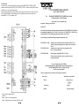
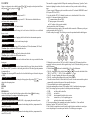
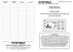
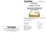
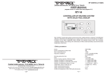
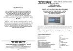
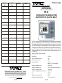
Admission date Realization date Signature RT16/2013/v.1.0 ANG Remarks Zakład elektroniczny TATAREK Jerzy Tatarek USER MANUAL software 1.0 (14.06.2013 software v1.0) RT-16 CONTROLLER OF THE HEATING SYSTEM EQUIPPED WITH THE SOLID FUEL BOILER The RT-16 controller controls the central heating system with the boiler equipped with an automatic fuel feeder, in which changing the cycles of feeding the fuel alters the boiler temperature. The applied PID algorithm enables the operation with automatic modulation of the boiler power. The generated heat is delivered depending on the demand, thanks to which the combustion process is evenly distributed (there is no sudden increase in temperature of the combustion chamber and the chimney), more efficient and guarantees long life of the heating system. The RT-16 controls the fan, the CWU loading pump (utility water) and 2 central heating circulations equipped with mixing valves and room thermostats. 1.Basic parameters of the controller Supply voltage Power consumption without load Maximum connection power Operating conditions Zakład elektroniczny TATAREK Jerzy Tatarek 50-559 Wroclaw, 75 Swieradowska st. ph. (071) 367-21-67, 373-14-88, fax 373-14-58; Tax index number 899-020-21-48; Bank account: BZ WBK S.A. WROCLAW 6910901522-0000-0000-5201-9335 www.tatarek.com.pl.; E-mail: [email protected] 16 230V/50Hz 10W 1400W 5÷50 oC, humidity 10÷80% no condensation 300W/230VAC 250W/230VAC variable control of rotation 150W/230VAC 450W/230VAC 6,3A/250V NTC 2.2k 2 oC with resolution 0,1 oC Output for controlling the feeder Output for controlling the fan Output for controlling the pumps Output for controlling the heater of the biomass Fuse Temperature sensors of the boiler Temperature measurement precision 1 2. Overview The controller is a module-based device. It consists of the OPERATIONAL PANEL “RT-16” mounted on the boiler and the EXECUTIVE MODULE “RT161” mounted on the DIN-Rail under the boiler cover or in the switching cabinet. The measuring signals from the sensors and the power supply of executive devices are connected to the executive module. The operational panel is connected with the executive module via a standard RJ45 1:1 UTP5 computer cable. CE CONFORMITY DECLARATION Ref. No. 58.RT.01.2007/1/B We, ZAKŁAD ELEKTRONICZNY TATAREK Jerzy Tatarek 75 Swieradowska St. , 50-559 Wroclaw declare under our sole responsibility that the product: Heating system controller model: RT-16 is in conformity with the basic requirements included in Directive EMC 2004/108/WE of 15.12.2004 (the electromagnetic compatibility law of 13.04.07) and Directive LVD 2006/95/WE of 21.08.07 (Laws Journal of 2007 No. 155 pos. 1098) regarding the requirements for electric devices. white green To the conformity evaluation the following harmonized standards were used: PN-EN 60730-2-1: 2002 PN-EN 60730-1: 2002 PN-EN 55022: 2000 - FUSE Automatic electric regulators for house usage and the like. Part 2-1: Specific requirements regarding electric regulators for electric house devices Automatic electric regulators for house usage and the like. Part 1: General requirements. Electromagnetic compatibility (EMC)- IT devices Characteristics of radioelectric noises. Acceptable levels and measurement methods Electronic Engineering Plant TATAREK has initiated management system and complies with the following standard : ISO9001: 2000 CERTIFICATE No. 133/2004 of 01.2004 Polish Foreign Trade Chamber The last two digits of the year in which the CE marking was affixed: 07 Place of issue: Manufacturer representative: Wroclaw Fig.1. Executive module wiring INPUTS: Tzew - Sensor of external temperature Tcwu - Temperature sensor of warm utility water tank 2 Mirosław Zasępa Date of issue: Position: 08.2007 Electronic Designer 15 WARRANTY 1.Warranty is valid [24] months from the date of sale. 2.Producer does not take responsibility for any mechanical damages made by user. 3.MAKING REPAIRS OR MODYFYING THE CONTROLLER BY USER IS FORBIDDEN AND CAUSES WARRANTY CANCELATION 4.Warranty card is valid only with date of sale, seller's signature and stamp 5.Warranty and after-warranty repairs should be done only by producer, damagedcontrollers should be sent to the producer in order to make all repairs needed. 6.Warranty protection involves the EU 7.Warranty does not exclude, not restrict and not suspend buyer’s rights coming from the incompatibility of the article with the agreement (Laws Journal No. 141 Pos. 1176) WARNING ! ANY MODIFICATION OF THE CONTROLLER MADE BY THE USER CAN BE THE CAUSE OF SAFETY CONDITIONS DETERIORATION AND CAN EXPOSE THE USER TO ELECTRIC SHOCK OR DAMAGE DEVICES SUPPLIED. Connection cable of the controller may be replaced only bythe producer or his authorized service WARNING! 1. Producer does not take the responsibility for damage caused by atmospheric discharge 2. and overvoltage in the mains 3. Burnt fuses are not subject to warranty replacement Date of sale Seller's signature and stamp ARGO-FILM Recycling Plant No. 6 180 Krakowska st., 52-015 Wroclaw Worn out electronic and electric devices must be transfered to ph.: 071 794 43 01, 0 515 122 142 the utilization collection place, where will be accepted for free Register No.. GIOS: E 0002240WZ Tkcz - Sensor of the delivery temperature of the boiler Tkcp - Sensor of the return temperature of the boiler Tpod - Temperature sensor of the feeder Tco1 - Temperature sensor of the heating system (behind the mixing valve 1) Tco2 - Temperature sensor of the heating system (behind the mixing valve 2) TP1 - Room thermostat of the circuit CO1 TP2 - Room thermostat of the circuit CO2 Tspal - Temperature sensor of waste gas RS485 -Connection to other executive modules (option) RJ45 - Connection to the operational panel RT16 OUTPUTS: M2 - Drive of the mixing valve 2(Terminal marked "-" means shutting the valve), 150W max M1 - Drive of the mixing valve 1(Terminal marked "-" means shutting the valve), 150W max G - Heater of firing up the biomass, 450W max P.CO2 - Pump CO2, 150W max Note: CO=CH(central heating) P.CWU - Pump CWU, 150W max P.CO1 - Pump CO1, 150W max STB - Safety thermostat W - Fan, 250W max PD - Drive of the feeder, 300W max SERVICE: Service LED diode indicates the operation of the module: - blinking orange - awaiting the start of the controller - blinking green – correct operation - fast blinking red – no connection with the operational panel, the outputs are turned off. The service switch is used while connecting other executive modules. It should be set to ON (both positions to ON acc. to the figure) !The boiler operates correctly if you connect the sensor Tkcz (delivery temperature of the boiler) and sensor Tpod (temperature of the feeder). ! The other sensors enable additional features of the controller: Tcwu - controls loading the CWU tank via the P.CWU pump Tco1 - connecting this sensor indicates that in the heating system an electronically controlled mixing valve M1 is mounted. The sensor controls the opening of the valve M1 so the preset temperature in the circuit CO1 is reached. Tkcp - sensor along with the 4-way mixing valve M1 turns on the protection of the boiler against too low water temperature returning from the system (protection against a premature corrosion) Tco2 - connecting this sensor indicates that in the heating system an electronically controlled mixing valve M2 is mounted. The sensor controls the opening of the valve M2 so the preset temperature in the circuit CO2 is reached. TP1 - room thermostat limits the heating in the circuit CO1 if the temperature exceeds the preset value of the thermostat TP2 - room thermostat limits the heating in the circuit CO2 if the temperature exceeds the preset value of the thermostat Tzew - sensor of external temperature enables the weather compensation of the circuit CO1 and CO2 Tspal - sensor of waste gas is required to automatically fire the biomass up. Zakład elektroniczny TATAREK Jerzy Tatarek 50-559 Wroclaw, 75 Swieradowska st ph. (071) 367-21-67, 373-14-88, fax 373-14-58; tax index number 899-020-21-48; Bank account : BZ WBK S.A. O/WROCŁAW 6910901522-0000-0000-5201-9335 www.tatarek.com.pl.; E-mail: [email protected] 14 3 ! Operation of the pump CO: 5 Weather compensation (weather control) P.CO1 (without the mixing valve M1) –the pump turns on after exceeding the minimum temperature of the boiler (protection against corrosion) P.CO1 (the mixing valve M1 installed) – the pump runs in the continuous mode and can be switched off in emergency in case of exceeding the maximum temperature of the circulation. The P.CO1 switches on after exceeding the maximum temperature of the boiler. P.CO2 - When the mixing valve M2 is installed in the heating system causes the selection of the second heating ciruit CO2 that consists of the valve M2, pump P.CO2, sensor Tco2 and optionally room thermostat TP2 and sensor Tzew. The pump P.CO2 runs in the continuous mode and can be switched off in emergency in case of exceeding the maximum temperature of the circulation. The controller can automatically detect the preset temperature of the heating system on the base of measurement of external temperature and programmed heating curve. The slope (number) of the heating curve characterizes the thermal properties of the building: 3. Servicing the controller At a well chosen heating curve the internal temperature ought to be constant, regardless of the external temperature. If at a decreasing external temperature the internal one drops then you need to select a higher number of the curve, if it increases then you select a lower number of the curve. The required temperature of the room is defined by the curve parameter "Tpok". It shifts the curve upwards or downwards to ensure a proper heat comfort. In the controller you can choose independently the weather compensation for the circulation CO1 and CO2. The choice of the curve number 0 indicates turning off the weather compensation - then with the parameter P01 "Temperatura ogrzewania 1"(Heating temperature 1) you set directly the preset temperature (respectively the parameter P02 for CO2). After switching on the power of the boiler the operational panel activates. The panel consists of control elements (Fig.1). The status of the controller is presented on the graphic display(1). The displayed screens inform about an operation of devices, temperature of the sensor and enable changing the patameters and the like. 1 2 3 4 Heating Building Heating curve number Floor Heater-based cold warm warmed up The parameter P11 „Charakterystyka pogodowa 1”("Weather characteristics 1") enables setting the heating curve for CO1 (respectively P12 for CO2) With the button you select the highlighted field: (1) room temperature (2) curve number You change the values with the buttons On the graph the controller automatically sets the preset temperature (3) Entering new settings follows after pressing 5 8 7 Fig.1 View of the operational panel (1) Display (2) Return button (3) Upward button (4) Confirmation button (5) Downward button (6) Information button (7) The LED diode of the status of the controller: WORK (green) DEFECT (red) AWAITING THE READINESS (orange) (8) Shield-protected USB port (pendrive) 4 6 ! The sensor of external temperature needs to be mounted on the shaded wall of the building. At a half height no less than 2m above the ground far away from windows and ventilation openings. 13 3.1 Start screen After switching on the power the start screen shows up on the display indicating awaiting service actions (e.g. upgrading the software). The displayed asterisks indicate the countdown to the start. If during that initial time the button (6) installed software is shown. 3.2 Main screen 10. The update of the executive module software begins. the rotating flag shows up and at the end the operation status displays in the field (2) E-DIR no folder with the data files E-FILE no data files E-CONF data incompatible with the device version Exx internal error „xx” of the updating process OK update has been carried out successfully. 11. The correct updating of the executive module software should last 2..3 min and finish displaying the status "OK". 12. The end of the updating process is indicated by a blinking field (1), which recalls about removing the USB memory from the port. It causes an activation of the installed software . The restart of the controller with the new software takes place. ! While restarting, the controller checks software integrity. The incompatibility of software versions is indicated as a configuration error. is pressed the info about the The main screen informs about essential data of the boiler Field: (1) Sensor of external temperature (2) Temperature sensor CWU (3) Temperature sensor CO1 (4) Instantaneous power of the boiler (5) Operation PID or MANUAL BURNING (with the feeder turned off) (6) Current temperature on the output of the boiler (7) Messages field (8) Additional signalizations ! Caution: without the sensor the „--.-” text shows up. 4 Room thermostat The controller has got the input to connect a room thermostat (TP) of any kind, equipped with a relay nonvoltage output. TP1 concerns the main heating circuit. If there's the mixing valve M2, then the second heating circuit can be equipped with its own thermostat TP2 or can be controlled by the TP1 thermostat (in that case you need to set the parameter "Przyporządkowanie TP1"(Assignment TP1) in the MENU OPCJI SERWISOWYCH "Termostaty pokojowe"( SERVICE OPTIONS MENU "Room thermostats"). So long as the temperature measured by the thermostat is below the preset value , the controller operates normally. Otherwise, it's indicated by a icon on the main screen , the controller modifies its operations: The preset temperature of the heating circulation drops by the value set in the parameter "termostat X obniżenie" (thermostat X lowering) and the pump CO runs cyclically if the circuit isn't equipped with the mixing valve. If the thermostat is equipped with contactss that short if the room temperature is above the preset value you need to set the parameter "Typ styków termostatu" (Contact type of thermostat) in the MENU OPCJI SERWISOWYCH "Termostaty pokojowe" (SERVICE OPTIONS MENU "Room thermostats") to the value COM+NC. For the normally opened contacts NO you need to set COM+NO. ! The thermostat needs to be placed in a control room, in which there are no thermostatic near-the heater valves. It must be mounted at a height of about 1,5m above ground faraway from windows and heaters. 12 (81) Heater of firing up the biomass is turned on (82) Room thermostat TP2 is active (83) Room thermostat TP1 is active (84) Dirt of the boiler (high temperature of waste gas) (85) Operation mode SUMMER (only CWU) (86) The cycle of firing up the biomass is switched on At the main screen level the buttons function as follows: entering the menu (see ch.3.2.1) activates the firing-up process (see ch.3.2.1.1) entering the information screen (see ch.3.3) 5 3.2.1 MENU Going over the menu is done with the buttons after pressing and going out with and . Entering the selected position follows 01 Heating temperature 1 The preset temperature of the main heating circuit CO1 02 Heating temperature 2 The preset temperature of the main heating circuit CO1. This function is disabled without a servo-motor on the mixing valve M2. 03 Temperature CWU The temperature to which the CWU tank is loaded 04 Burning mode It enables going over to the manual burning (the feeder function is disabled) in case an additional furnace is used. 05 Feeder pause Time between successive cycles of suppling the fuel to the boiler in the automatic operation. 06 Fan power Fan power adjustable to the fuel, boiler and chimney draught. 05 PID – power Sets the boiler power to the minimum (30% load)/medium (50% load)/maximum (100% load) ! Caution: option available at the PID control turned on. 06 PID - corrections Settings correction (%) of the air and fuel in relation to the defaults. ! Caution: option available at the PID control turned on. 07 Feeder maintenance Time after which the controller switches on the feeder and fan in order to prevent the boiler from burning out. 08 Boiler/fuel type Selection of the fuel type (coal, pea coal or biomass) and boiler type. Having selected the boiler type "Klimosz INNE" you need to set the feeding time of the fuel. For other types that parameter is automatically set. ! Caution: after selecting the PID control the list of available boiler types is limited to the power of 45kW. 09 Firing up the boiler Manual control of the feeder and fan during the firing-up phase. By pressing : and you can choose the subsequent options: STOP FEEDER FAN FEEDER+FAN After firing up the fuel you finish the firing-up phase with the button and the burning continues according to the settings of the automatic operation 10 Heating SUMMER/WINTER Selection of the operation mode SUMMER(LATO) - only preparing the warm utility water 11 Weather characteristic curve 1 Setting the heating curve and room temperature for calculating the delivery temperature of the circuit CO1 (see ch.5) 12 Weather characteristic curve 2 Setting the heating curve and room temperature for calculating the delivery temperature of the circuit CO2 (see ch.5) 6 The controller is equipped with the USB port for connecting a flash memory ("pendrive") and a function of updating the software, In order to make use of that you need to take the following steps: 1. Prepare a typical USB memory device suitable to work on PC and under WINDOWS control (File system FAT16 or FAT32). 2. Copy the subfolder "RT16_0" obtained from the service, which includes 3 files with an extension "x" and names beginning with the letter "U" (communications software USB), "M" (main program of the controller) and "A" (software of the executive module) , into the main folder of the USB memory. 3. At the diconnected power supply of the controller/boiler connect the USB memory to the port on the operational panel (Fig.1 pos. 8) 4. Switch on the power supply. The following screen on the operational module should appear: 5. Without this screen or the text "OK" in the field (1) indicates the USB memory hasn't been recognized. In this case you need to follow again the steps 3 and 4. If that doesn't help you can try other USB memory. 6. With the button you choose the shaded field (6),(3) or (4), which means: Field (6) - changing the folder with the buttons and (You can alter the default folder "RT16_0" to "RT16_1" ...."RT16_9" if the required files are there) Field (3) - the start of updating the software after pressing Field (4) - cancelling the updating and the restart of the controller Time for decision is limited, of which the field (2) recalls. After the counter ends the update is automatically rejected and the restart of the controller takes place. 7. The started update begins with the operational panel. At first the communications software USB is updated - field (8) and then the main program field(7), the rotating flag shows up and at the end the operation status displays. E-DIR no folder with the data files E-FILE no data files E-CONF data incompatible with the device version Exx internal error „xx” of the updating process OK update has been carried out successfully. 8. The correct updating of the operational panel software should last 1..2 min and finish displaying 2 statuses "OK" in the field (7) and (8). 9. After a while the controller activates the newly installed software and under its control goes over to the updating of the executive panel software. The following screen appears: 11 Field : (1) presents the operation of the pump CO1 (if it runs the icon blinks) (2) Preset temperature of the boiler, that is, calculated by the controller (3) presents the operation of the main mixing valve (the upward arrow - opening; the downward arrow - closing) (4) presents the operation of the fan (if it operates the icon blinks) (5) presents the operation of the feeder (if it operates the icon blinks) Screen 2: On the right side of the screen the numeric values show: 1.Reading of the temperature sensor of the boiler DELIVERY 2.Reading of the temperature sensor of the boiler RETURN 3.Reading of the temperature sensor CO1 4.Reading of the temperature sensor CWU 5.Reading of the temperature sensor CO2 6.7.! Caution:Without the sensor the text „--.-” shows up. Field : (1) presents the operation of the pump CWU(if it runs the icon blinks) (2) presents the operation of the pump CO1(if it runs the icon blinks) (3) presents the operation of the 3-way mixing valve of the circulation CO2 (the upward arrow opening; the downward arrow - closing) (4) presents the operation of the pump CO2(if it runs the icon blinks) (5) presents the operation of the main mixing valve (the upward arrow - opening; the downward arrow - closing) Screen 3: The versions of the software of the main module of the controller (MA), communications module USB (UA) and executive module (1A). The return to the main screen takes place after pressing again or at any moment 3.5 Updating the software of the controller ! This option is only for the service and trained users. Incorrect update may lead to the locking of the controller. 10 13 Thermostat 1 lowering Lowering the temperature CO1 after connecting the room thermostat TP1 14 Thermostat 2 lowering Lowering the temperature CO2 after connecting the room thermostat TP2 15 Settings INNE (OTHERS) 01 Sounds and alarms Turning on/off the sound of button clicking and alarm signal 02 Clock Setting the actual date and hour 03 Screen backlight Setting the screen backlight in an inactive status of the controller 16 Service options These additional settings specify the operation of the controller. After activating this function, you need to give a password. ! SERVICE OPTIONS ADJUST THE CONTROLLER TO THE FEATURES OF THE BOILER AND HEATING SYSTEM. THEIR CHANGE SHOULD BE CONSULTED WITH THE PRODUCER OF THE BOILER OR AN INSTALLER. ILL-CONSIDERED CHANGES MAY CAUSE AN UNSTABLE AND INEFFICIENT OPERATION OF THE SYSTEM. 01 Minimum temperature of the boiler It limits the minimum preset temperature of the boiler. Below that temperature the pump CO1 switches off (without the mixing valve) or the mixing valve closes. 02 Maximum temperature of the boiler It limits the maximum temperature of the boiler 03 Critical temperature of the boiler Exceeding on the output of the boiler the maximum temperature (P02) by a critical value(P03) generates an alarm situation status leading to the cooling down of the boiler as soon as possible. The pumps CO1 and CWU run, the mixing valve opens up and the feeder and fan turns off. 04 Protection temperature of the boiler Below that return temperature of the boiler the mixing valve M1 closes, protecting the boiler against a premature corrosion. For this feature to function you need a controllable valve M1 and a sensor of the return temperature "Tkcp". 05 Correction of the feeder It sets a constant level of the fuel in the retort 06 Fan - firing up It sets a blowing force during the firing-up phase of the boiler 07 Alarm temperature of the feeder Exceeding this temperature of the feeder activates an alarm push-out of the fuel in order to prevent the embers from moving back. 08 Pump CO It sets an operation time and pause of the pump CO1 in configuration without the mixing valve M1 at the activation of the room thermostat TP1 (in order to limit the heat flowing into the system) 09 Hysteresis CO Temperature hysteresis of turning on the pump CO 10 Hysteresis CWU Temperature hysteresis of turning on the pump CWU 7 11 CWU priority ON/OFF It turns on the priority of CWU heating 12 CWU priority – time It turns off the CWU priority if the required heating up of the CWU in the preset time doesn't occur. 13 CWUadditional temperature It increases the temperature of the boiler if the priority heating up of the CWU is required 14 Lack of the fuel ON/OFF It turns off the detection of fuel shortage (based on the analysis of temperature on the boiler output). 15 Lack of the fuel - time Detection time of fuel shortage before reporting the error of fuel deficit. 16 Cleaning up the boiler Waste gas temperature above which the need for cleaning up the boiler is reported 17 PID on/off It enables the PID feature 18 Additional temperature of the boiler It increases the boiler temperature in configuration with the mixing valve 19 Room thermostats It configures the quantity and type of room thermostats (see ch.4) 20 Mixing valve MAIN M1 It configures the mixing valve M1: 01 Opening time 02 Minimum temperature of the circulation 03 Maximum temperature of the circulation 04 Correction of response time 21 Mixing valve 3 – way M2 It configures the mixing valve M2: 01 Opening time 02 Minimum temperature of the circulation 03 Maximum temperature of the circulation 04 Correction of response time 22 Biomass - firing up It configures the firing-up process of the biomass 01 Automatic firing-up is turned on 02 Preliminary charge 03 Operation time of the feeder 04 Pause time of the feeder 05 Preliminary charge 06 Operation time of the heater 07 Turn-off temperature of the firing-up 08 Delay time of detecting the fire 17 Test of the controller By testing you can check all the inputs and force out the outputs of the executive module RT161. # With the button you go over the screens that read in the inputs # For the room thermostats TP1 and TP2 the "++" text means activity and the "--" one means inactivity (depending on the configuration of the thermostat). # For the STB input the"--" text means a correct state, that is, the STB is short-circuited, the text "!!" indicates a operating STB, so the STB is opened. # The button enables going over to the output screens. By pressing and you can select the successive outputs, always the only one is turned on - that highlighted. The return to the automatic operation from the testing follows after pressing 18 Default parameters After confirming that function the question about language follows and then the inserted settings are removed and the defaults are valid. 8 9 3.3 Alarm states Any alarm situation is signalled on the operational panel by the red LED, sound signal (if this feature is enabled) and the corresponding message in the messages field on the main screen. Pressing causes displaying more details about the alarm. Cancelling the alarm and return to the normal operation (if the cause of the alarm is removed) takes place after pressing The following states are detected: Damage of the executive module RT161 (no communication with the module) Incorrect version of the software of the executive module RT161 Incorrect version of the software of USB in the operational panel Damage of the temperature sensor of the boiler Damage of the temperature sensor of the feeder The boiler temperature exceeded the limit value Failure of firing up the biomass Activation of the additional thermal protection STB Lack of the fuel, fire or a low caloric value of the fuel Exceeding the feeder temperature. An alarm push-out of the fuel 3.4 Information screens When the main screen is shown on the operational panel you can check the state of the basic circuits of the controller. Pressing displays the successive infromation screens: Screen 1: On the right side of the screen the numeric values show: 1.Reading of the temperature sensor of the boiler DELIVERY 2.Reading of the temperature sensor of the boiler RETURN 3.Reading of the temperature sensor CO1 4.Reading of the temperature sensor of the FEEDER 5.Reading of the temperature sensor of WASTE GAS 6.Reading of the sensor of external temperature 7.(Boiler icon).The PRESET temperature of the BOILER, tha is, calculated by the controller ! Caution:Without the sensor the text „--.-” shows up.