1
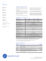
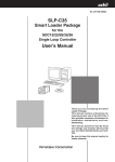
GE
Security
EST Fire & Life Safety
EST3 Multiplexed Fire Alarm System
Overview
Standard Features
The 3-SSDC1 and 3-SDDC1 Signature Driver Controller modules provide an intelligent interface between the 3-CPU3 module and Signature Series devices. Each module contains its own microprocessor
used to coordinate, process and interpret information received
from and sent to Signature devices. Power and communications is
received directly from the control panel rail assembly. The 3-SSDC1
Single Signature Driver Controller module supports one Signature
Data circuit, while the 3-SDDC1 Signature Dual Driver Controller
module supports two Signature circuits. Both modules occupy one
rail space in the fire alarm control cabinet and provide removable
field wiring terminals to aid installation.
• One or two circuit versions
Innovative design gives the 3-SSDC1/3-SDDC1 and Signature
devices truly “distributed intelligence”. Signature detectors and
modules have their own on-board microprocessor communicating
with the loop controller in a fully digital communication format. This
increases the accuracy of the information coming to and from the
loop controller by reducing the effects of capacitance and noise.
With decentralized intelligence much of the decision making moves
from the loop controller to the devices. Advanced fire detection algorithms processed within the Signature devices effectively end unwanted alarms. Environmental compensation and multiple sensing element
decision making operations are resident in the devices. Intelligent
devices allow the Signature Controllers to execute communication and
system functions with greater speed and low baud rates, increasing
the accuracy of information transmitted between the loop controller
and devices.
• Dedicated microprocessor control
• Full digital communication
• Specialized communication protocol
– Less sensitive to cable characteristics
– Utilize existing wiring in most applications
• Loop alarm in under 750 milliseconds
• Device location supervision
– Unexpected additional device addresses
– Missing device addresses
– Switched device locations
– Programmed device parameters
• Automatic nonvolatile as-built mapping
– Stores “actual” and “expected” device data
– Stores physical connection sequence including “T” taps
• Automatic day/night sensitivity
• Supports up to 250 intelligent Signature detectors
and 250 Intelligent Signature Modules
• Up to five 3-SDDC1s per node
– Total of 10 Signature circuits
• Removable field wiring terminal blocks
• Multiple survival modes — stand alone
• Fully backward compatible with 3-SSDC and 3-SDDC
Signature Driver
Controller Modules
3-SSDC1, 3-SDDC1, 3-SSDC1-MB, 3-SDC1
EN54-2:1997+A1 and
EN54-4:1997+A1:2002+A2
pending
Data Sheet 85010-0129 Issue 4
Not to be used for installation purposes. Page of 4
Application
If the attributes are not the same the 3-SSDC1/3-SDDC1 will send a
map fault indication to the 3-CPU3 and post a trouble indicating the
specific devices in fault.
The 3-SSDC1/3-SDDC1 also monitors the Signature Series devices
Typical Wiring
To enhance survivability of the system the 3-SSDC1/3-SDDC1 supports a standalone mode for Signature devices. Two catastrophic
failure modes are supported. If the 3-CPU(1/3) fails, the loop controller will continue to poll its devices. If an alarm is detected it will be
sent on the local rail communication bus and received by other
local rail modules. A common alarm condition throughout the panel
will result. If the local rail module (3-SSDC1/3-SDDC1) fails, and a
device (smoke or module) detects an alarm, specialized circuitry will
make the node aware of the alarm condition. The 3-CPU(1/3) will
communicate the alarm condition to the rest of the network. Having
multiple redundant modes is paramount in a life safety system.
3
1
Circuit #1
The 3-SSDC1/3-SDDC1 then compares the “Actual” physical device
data to the “Expected” site specific program data. If any correlations are different, the loop controller issues a trouble to the CPU
identifying the devices which do not match and posting a map fault.
Through the 3-CPU3’s RS-232 port a graphical map of the loop can
be uploaded depicting each device’s location on the loop, including
branches (T-Taps) and all of the physical attributes associated with
the device. This diagnostic information is unparalleled in the fire
detection industry and vital for keeping accurate records on how
the system was installed.
During installation a common problem with analog/ addressable
systems is locating ground faults. The 3-SSDC1 and 3-SDDC1 controllers have the ability to locate ground faults by specific module,
speeding up the troubleshooting process. Another significant
advantage of the 3-SSDC1/3-SDDC1 controllers during commission-
SDC #1 Smoke
Power
+
6
1
2
3
4
5
6
7
8
9
10
To TB1 on 3-SDDC1 Module
TB1
3-SDDC1
SIGNATURE
DUAL
DRIVER
CONTROLLER
MODULE
Class B Configuration Shown (Typical)
TB2
To TB2 on 3-SDDC1 Module
1
Every time the 3-SSDC1/3-SDDC1 communicates with a detector
the green LED on the detector flashes. Normal green LED activity
is not disturbing to building occupants, but can be quickly spotted
by a maintenance technician. The red LED on the detector turns on
only in the alarm condition.
The 3-SSDC1/3-SDDC1 also supervises the device wiring, physical
location of each device and the programmed device characteristics. This GE Security/Signature Series unique characteristic is
accomplished by “MAPPING” the Signature circuit and committing
the map to memory. Upon power up the loop controller will scan
device serial numbers and map their physical location sequence on
the loop, including “T” taps. After mapping is complete the controller automatically addresses each detector and module through
downloading over the loop. There are no switches or dials to set.
Each device is assigned a unique soft address generated by the site
specific program.
5
2
3
4
5
6
7
8
9
10
Circuit #2
1
5
SDC #2 Smoke
Power
6
3
1
Class A Configuration Shown (Typical)
4
3
Wiring Notes
1
Maximum #12 AWG (1.5 mm2) wire;
2
minimum #18 AWG (0.75 mm ).
2.
All wiring supervised and power limited.
3
Shields (if used) must be continuous and
free from Earth Ground.
4
Class A wiring.
5
Class B wiring.
6
To Universal Module or MAB module
when 2-wire smokes are powered from
the module.
Circuit #1
SDC #1 Smoke
Power
+
+
1
2
3
4
6
5
6
7
8
9
10
To TB1 on 3-SDDC1 Module
TB1
3-SDDC1
SIGNATURE
DUAL
DRIVER
CONTROLLER
MODULE
TB2
To TB2 on 3-SDDC1 Module
Circuit #2
1
2
SDC #2 Smoke
Power
6
Class A Configuration Shown (Typical)
3
4
5
6
7
8
+
The unique use of “BROADCAST POLLING” combined with “DIRECT
ADDRESS SEARCH” ensures that only new information is transmitted allowing a reduced baud rate with fast response time. The low
baud rate is ideal for retrofit applications since in most applications
existing wiring can be used.
During maintenance, should groups of detector heads be removed
for service and returned into the wrong smoke detector base (location), the 3-SSDC1/3-SDDC1 will automatically detect the problem. If
the attributes of the switched devices are the same, the system will
automatically download the correct soft addresses and algorithms
to the devices (maintaining location supervision).
9
10
+
The 3-SSDC1 and 3-SDDC1 use advanced communication formats
that provide exceptional response. Using a “BROADCAST POLL” the
loop controller checks the entire device circuit for any changes of
state. Should one or more devices report a change the 3-SSDC1/3SDDC1 uses “DIRECT ADDRESS SEARCH” to find reporting device(s).
Devices that have entered the alarm state or become active are
located nearly instantaneously.
ing is electronic addressing and mapping. This eliminates duplicate
addresses, which are also very difficult for most systems to locate.
+
Up to 125 detectors and 125 modules are supported over a single
pair of wires by the 3-SDC1 Signature Cards that plug into the
Signature controller modules. Both Class A wiring (style 6 or style
7) and Class B (style 4) wiring are supported. Loop distances over
11,000 feet (3300m) are possible.
3
1
4
Data Sheet 85010-0129 Issue 4
Not to be used for installation purposes. Page of 4
for maintenance and trouble conditions. Each smoke detector
contains intelligence to adjust with environmental changes. This
expands the amount of time required between cleaning while
maintaining a constant alarm threshold. As the detector begins to
exhaust the environmental compensation, and reaches the 80%
level, the 3-SSDC1/3-SDDC1 will indicate a maintenance alert or
dirty condition to the 3-CPU and indicate the specific device requiring cleaning. If cleaning is not performed the detector will continue
to operate until all of its environmental compensation is utilized. At
this point the 3-SSDC1/3-SDDC1 sends a dirty trouble indication to
the 3-CPU and posts a trouble condition. If maintenance is still not
performed the Signature detector will automatically remove itself
from service once the programmed threshold window has been
breached (preventing a false alarm).
Remote test capability permits devices to be put in alarm, prealarm,
supervisory, monitor, or security alarm or trouble from the panel
menu or controls. This facilitates testing of smoke and heat detectors as well as monitor and security devices.
The 3-SSDC1 and 3-SDDC1 local rail modules modules are fully
backwards compatible with the 3-SSDC and 3-SDDC local rail
modules. 3-SSDC1 and 3-SDDC1 modules provide additional onboard memory to facilitate future Synergy functions. To upgrade a
3-SSDC/3-SDDC to a 3-SSDC1/3-SDDC1 respectively, replace the
3-SSDC/3-SDDC Local Rail Module with a 3-SDDC1-MB Local Rail
Module and reuse the 3-SDC Signature Device Cards and filters.
Specifications (Signature Circuits)
Charts assume wire and devices are evenly distributed over length of circuit
Non-twisted, non shielded wire
Device type
# of Detectors
# of Module Addresses
Detectors only
125
0
Modules only
0
125
125
125
63
55 + 9 SIGA-UM
0
107 + 9 SIGA-UM
Detectors and Modules
Detectors and Modules
with 2-wire smokes
Modules
with 2-wire smokes
#14 AWG (20pf/foot)
(2.53 Ohm/1000ft)
14,752 feet
(4,497 meters)
12,599 feet (3,840
meters)
5,738 feet
(1,749 meters)
7,623 feet
(2,324 meters)
3,798 feet
(1,158 meters)
#16 AWG (20pf/foot)
(4.02 Ohm/1000ft)
9,275 feet
(2,827 meters)
7,921 feet (2,414
meters)
3,608 feet
(1,100 meters)
4,793 feet
(1,461 meters)
2,388 feet
(728 meters)
#18 AWG (20pf/foot)
(6.38 Ohm/1000ft)
5,839 feet
(1,780 meters)
4,986 feet
(1,520 meters)
2,271 feet
(692 meters)
3,017 feet
(920 meters)
1,503 feet
(458 meters)
Twisted pair non shielded wire
#14 AWG
(38pf/foot)
(2.53 Ohm/
1000ft)
13,157 feet
(4,010 m)
12,599 feet
(3,840 m)
5,738 feet
(1,749 m)
1.5mm²
(36pf/foot)
(3.75 Ohm/
1000ft)
9,933 feet
(3,028 m)
8,483 feet
(2,586 m)
3,864 feet
(1,178 m)
#16 AWG
(36pf/foot)
(4.02 Ohm/
1000ft)
9,275 feet
(2,827 m)
7,921 feet
(2,414 m)
3,608 feet
(1,100 m)
1.0mm²
(25pf/foot)
(5.51 Ohm/
1000ft)
6,760 feet
(2,061 m)
5,774 feet
(1,760 m)
2,630 feet
(802 m)
#18 AWG
(25pf/foot)
(6.38 Ohm/
1000ft)
5,839 feet
(1,780 m)
4,986 feet
(1,520 m)
2,271 feet
(692 m)
55 + 9 SIGA-UM
7,623 feet
(2,324 m)
5,133 feet
(1,565 m)
4,793 feet
(1,461 m)
3,494 feet
(1,065 m)
3,017 feet
(920 m)
107 + 9 SIGA-UM
3,798 feet
(1,158 m)
2,558 feet
(780 m)
2,388 feet
(728 m)
1,741 feet
(531 m)
1,503 feet
(458 m)
# of Detectors
# of Module
Addresses
Detectors only
125
0
Modules Only
0
125
125
125
63
0
Device Type
Detectors
& Modules
Detectors and
modules with
2-wire smokes
Modules with
2-wire smokes
Twisted pair shielded wire
Device Type
# of Detectors
# of Module Addresses
Detectors only
125
0
Modules Only
0
125
125
125
63
55 + 9 SIGA-UM
0
107 + 9 SIGA-UM
Detectors & Modules
Detectors and modules
with 2-wire smokes
Modules with 2-wire
smokes
#14 AWG (84pf/foot)
(2.53 Ohm/1,000ft)
5,952 feet
(1,814 meters)
5,952 feet
(1,814 meters)
5,738 feet
(1,749 meters)
5,952 feet
(1,814 meters)
2,558 feet
(780 meters)
#16 AWG (82pf/foot)
(4.02 Ohm/1,000ft)
6,098 feet
(1,859 meters)
6,098 feet
(1,859 meters)
3,608 feet
(1,100 meters)
4,793 feet
(1,461 meters)
2,388 feet
(728 meters)
#18 AWG (58pf/foot)
(6.38 Ohm/1,000ft)
5,839 feet
(1,780 meters)
4,986 feet
(1,520 meters)
2,271 feet
(692 meters)
3,017 feet
(920 meters)
1,503 feet
(458 meters)
Data Sheet 85010-0129 Issue 4
Not to be used for installation purposes. Page of 4
GE
Security
U.S.
T 888-378-2329
F 866-503-3996
Canada
T 519 376 2430
F 519 376 7258
Asia
T 852 2907 8108
F 852 2142 5063
Australia
T 61 3 9259 4700
F 61 3 9259 4799
Europe
T 32 2 725 11 20
F 32 2 721 86 13
Latin America
T 305 593 4301
F 305 593 4300
www.gesecurity.com/est
© 2008 General Electric Company
All Rights Reserved
Signature Series is a Trademark
of GE Security.
Engineering Specification
The communication format between the
control panel and analog devices shall be
100% digital.
Class A or Class B with non-shielded, nontwisted wire. It must be possible to wire
branches (T-taps) with Class B wiring.
Loop alarm recognition must be within
750 milliseconds of a device going into the
alarm state, with system response time no
greater than 3 seconds. All devices shall
support remote testing.
The driver controller must be manufactured
in accordance with ISO 9001 standards.
It must be possible to wire the circuit as
The system must have tolerance to multiple
failures. There must be a standalone mode of
operation that will ensure the system is aware
of alarms even if the local rail or main CPU fails.
Specifications (controllers)
Catalog Number
Installation
Module Configuration
Operating Current
Operating Voltage
Address Requirements
Detectors Supported
Modules Supported
2-Wire Smoke Power Output
Conventional detectors
supported
Signature Circuit Voltage
Maximum Signature Circuit
Resistance
Maximum Signature Circuit
Capacitance
Communications Format
Circuit Wiring Styles
Termination
Permissable Wire Size
Agency Listings
Operating Environment
3-SSDC1
3-SDDC1
1 LRM Space
1 LRM Space
1 Addressable circuit (3-SDC1
2 Addressable circuits
Card) expandable to 2 circuits.
(3-SDC1 Cards)
Standby 144 mA Alarm 204 mA Standby 264 mA Alarm 336 mA
24 Vdc, Nominal
Automatic
125 per 3-SDC1 Card
125 Module Addresses per 3-SDC1 Card
100 mA per 3-SDC1 Card (not included in “Operating Current” above
150 of 100 µA type per circuit.
20 VDC +/- 5%
100 Ohms
0.33 µF
100% Digital
Class A or Class B
Removable plug-in terminal strip(s) on module
18 to 12 AWG (0.75 to 2.5 mm²)
UL, ULC, CE (see Note 1), LPCB EN54 pending (see Note 2).
32 °F (0 °C) to 120 °F (49 °C) 93% RH, non-condensing
Note 1: Other EST3 components are modularly listed under the following standards:
UL 864 categories: UOJZ, UOXX, UUKL and SYZV, UL 294 category ALVY, UL 609 category AOTX, UL 636 category
ANET, UL 1076 category APOU, UL 365 category APAW, UL 1610 category AMCX, UL 1635 category AMCX
ULC-S527, ULC-S301, ULC-S302, ULC-S303, ULC-S304, ULC-S306, ULC/ORD-C1076, ULC/ORD-C693
Please refer to EST3 Installation and Service Manual for complete system requirements.
Note 2: EN54-2:1997+A1 and EN54-4:1997+A1:2002+A2 pending
Ordering Information
Catalog
Number
3-SSDC1
3-SDDC1
3-SDC1
RFK1
3-SSDC1-MB
Shipping
Wt. lb (kg)
Description
Single Signature Driver Controller. Comes with one 3-SDC1 Device Card.
Mounts to Local Rail.
Dual Signature Driver Controller. Comes with two 3-SDC1s.
Mounts to Local Rail.
Signature Device Card - upgrades a 3-SSDC1 to a 3-SDDC1
Ferrite Clamp Kit required for EN54 compliance.
Dual Signature Driver Controller Motherboard (without 3-SDC1 device
cards). Use this motherboard for upgrading 3-SSDC or 3-SDDC to
3-SSDC1 or 3-SDDC1.
0.5 (0.23)
0.5 (0.23)
0.25 (0.11)
0.25 (0.11)
0.5 (.23)
Data Sheet 85010-0129 Issue 4
Not to be used for installation purposes. Page of 4